
Hello,
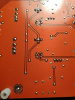
I redid all the soldering on the other side of the PCB and the problem is still the same. I have nothing on the left channel at the output of the preamplifier ...
I redid all the soldering on the other side of the PCB and the problem is still the same. I have nothing on the left channel at the output of the preamplifier ...
Try mechanically pressing with a plastic or wood tool at various places on the board, while looking at the output,
to look for an intermittent connection.
to look for an intermittent connection.
May I suggest, if you're tracing an AC signal and it "disappears", a DC bias fault may have the amp stuck on a supply rail. You may have better luck tracing DC voltages. Compare with the working channel for guidance.
Hello,
@rayma , I tried to press on the different zones but that does not change anything ...
Do you have an idea of the characteristics of the signal that I can inject on the test pin of the channel after having switched the jumpers to test ?
@BSST , Thank you for your help. I don't quite understand how I could do this.
Last edited:
Maybe someone more familiar with this unit can help you further.
Without proper information, more damage could be done than already exists.
Without proper information, more damage could be done than already exists.
I believe the preamp output bias should be nearly 0VDC. What DCV do you observe at the junction of R85, R85? Assuming it's dramatically not 0V, also measure some key points within the amp stage. I suggest the gates of U404-A, and U404-B, and U4A pin 1. I also suggest measuring the same points in the other channel (which I understanding is working?) for insight to what's expected. Depending what you report, we'll poke around at additional circuit nodes.Hello,
@rayma , I tried to press on the different zones but that does not change anything ...
Do you have an idea of the characteristics of the signal that I can inject on the test pin of the channel after having switched the jumpers to test ?
@BSST , Thank you for your help. I don't quite understand how I could do this.
Hi max123,
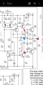
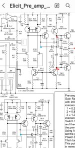
Are you still pursuing repair of this preamp? The board has post-jumper options to facilitate debuging the amplifier (i.e. TR7, TR9, etc.) independently of the WM8816.
Are you still pursuing repair of this preamp? The board has post-jumper options to facilitate debuging the amplifier (i.e. TR7, TR9, etc.) independently of the WM8816.
Good morning,
Thanks for your help !
I haven't had time to continue for the moment but I will get back to it this weekend!
I'll keep you informed !
Thanks for your help !
I haven't had time to continue for the moment but I will get back to it this weekend!
I'll keep you informed !
Good morning,
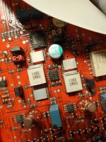
at the R84 / R85 junction I observe 6.9mV which is close to the R86 / R87 junction which is at 8.6mV
At U4A pin 1 i see 0.7V DC, i use the side of C33 to read the value.
At the junction of R4 and R57 i read 6.7 mv DC and on the other side (the good) at the junction of R7 ans R60 i have 3.3mV DC
The base of JF1B on the bad side (read at the junction of C47) is about 6.6mV and the good side is at 20mV (junction of C49) !
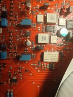
On the blue points i read the same value 13.28V DC
at the R84 / R85 junction I observe 6.9mV which is close to the R86 / R87 junction which is at 8.6mV
At U4A pin 1 i see 0.7V DC, i use the side of C33 to read the value.
At the junction of R4 and R57 i read 6.7 mv DC and on the other side (the good) at the junction of R7 ans R60 i have 3.3mV DC
The base of JF1B on the bad side (read at the junction of C47) is about 6.6mV and the good side is at 20mV (junction of C49) !
On the blue points i read the same value 13.28V DC
Attachments
Last edited:
The those voltages look very reasonable.
Help me refresh my memory--- you were having trouble getting a line input signal to pass though to the preamp output? Did I surmise that it was unclear if the WM8816 or the associated discrete amplifier was at fault?
My observation is that a couple of post jumpers can be moved to allow the amp to be tested independently of the volume control IC. Specifically: at JP2, move the jumper from 1-2 to 2-3 and at JP3, move the jumper from 1-2 to 2-3. This configures the amp for a gain of -10 (i.e. -R25/R34). You can inject test signals at "Left Test I/P" to confirm amplifier operation. This configuration also helps debug if there is a problem. Given your reported measurements, you'll probably confirm the amp is OK. If so, problem is probably U6. You can probe digital signals at U6 pins 6,9,10 to confirm control signals reach the IC. My understanding is the IC is discontinued. Good luck!
Thanks for your feedback.
could you confirm that a signal of 250mv peak to peak is good for the test?
could you confirm that a signal of 250mv peak to peak is good for the test?
- Home
- Amplifiers
- Solid State
- Rega Elicit MK2