Zinamp 3way active crossover

Just wanted to say I've had a great experience using this crossover module from Zinamp http://www.zinamp.co.uk/

Really easy to integrate and power etc. Dead quiet. It's easy to adjust the crossover points on the fly which is really what I was looking for. You can even change the shape of the slope depending on how your driver measures. It has baffle step compensation that you can use or not. Bass boost!

I'm still using the op amps that it came with but there are higher performance ones available

And if all of that wasn't great enough the technical service from the owner or whoever does his tech support has been flawless and so quick.

I guess this might be a review at this point. I just haven't seen many people talk about it on here and I feel like it is a really simple solution. It sounds really great to me

Same goes for neurochromes preamp power supply, super great to have such simple modules out there for those of us who have a tendency to blow things up

Attachments

  • PXL_20230712_233037695.jpg
    PXL_20230712_233037695.jpg
    370.2 KB · Views: 185
  • PXL_20230712_233031359.jpg
    PXL_20230712_233031359.jpg
    433.5 KB · Views: 170
  • Thank You
  • Like
Reactions: motokok and GM

Stylus Replacement For Realistic PortiPlay 13-1163

Hello!
I have recently re-discovered my Realistic PortiPlay 13-1163 ladybug phonograph, after being put away for months, if not years. It was working OK, but then it all went downhill from the point when I dropped the stylus on the textured platter mat to see what would happen. I am revisiting the project, but I cannot find an affordable stylus that would fit in this machine. Looking for somewhere that I could find one, please.
Thanks!

Expanding the Zaph B3S-B3N into a sound bar with sub

Hi fellow audio geeks.

I bought a couple B3N Drivers on sale awhile back. Now I'm trying to decide if I just build a couple boxes for them, ala Zaph. OR, do I buy a couple more, and make a sound bar with 2 + 2?
There's a 6" alum Airborne subwoofer on sale too, so I can use that. it's smooth past 1khz, so it would tie nicely close to the B3N's with a 200hz cutoff.

I haven't designed or built a crossover in EONS, so I'm looking at Zaph's parts list:
http://zaphaudio.com/audio-speaker18.html

QUESTIONS:
1. What kind of wattage is needed for these components... especially resistors? I see R5 is parallel with 2 others... so 3-5W ? but 30ohm... would 250mW be enough? I imagine most of the current there would flow through LF & C3, correct?

2. I'm in Canada, and the Inductor cost on Solen.ca is $9 each! makes the total parts for each speaker as much as the driver itself. I'm looking here: https://store.walectric.com/electrical/ but they have too many options... Any recommendations as to crossover parts? I'd be willing to order from US too.

I'm tempted to buy a couple more drivers, and put 2 in each side of a soundbar, with the sub in the middle (facing up or down, obviously a deep sound bar). If I paralleled them, this would change the impedance to 4ohms. Obviously, I could go to 16ohm in series too.
3. If I did this - what values would change for the crossover? Would a 4 or 16ohm load make for more affordable crossover parts?

thanks in advance!

For Sale Toshiba 2SK147-BL

I'm selling 15 pcs of these rare jfets,
New and unused (NOS).

I've measured their Idss (@9V/25°)
and the results are as follows:

10.14
10.56
10.89
10.91
11.30
11.86
13.80
14.08
14.13
14.21
14.40
14.60
14.62
14.96
15.25

As you can see, there are at least 3 pairs of them with very close Idss.

Guarantee they're authentic, if not, just send them back to me (I'll cover the returning cost) and get your money back.(you can write it on PayPal when you buy them).

Asking for SOLD

PM me if interested

Thanks!

Screenshot_20230913-114249~2.png

21" 30hz Cyclops Horn Resp Input Data

Hello DIYaudio,

Im giving designing my first subwoofer a go, for a La Voce SAN215.30. Its based on the cyclops design and then a design of a friend who came up with the plan originally, the idea is to not worry so much about size and get as much output in the 20 - 60/80 bandwidth, whilst still sounding nice. Any ideas welcome, TH, TL etc etc

I understand I need half SD for one of the horns/paths but cant seem to find any reading material on what other parameters need halving or leaving alone. I have looked! perhaps even scrolled past it. New to hornresp but am slowly working it out, I knew this day would come and am happy I have such a plethora of drivers lying around to design boxes for.

Thanks in advance.

Cerwin Vega RE Series 30 speakers both dead

While playing music outdoors for a friend's kid's grad party, a rogue storm rolled in fast and blew the tent covering my system off while it was playing before I could get to it to turn it off. Strangely the amp still functions, but both speakers are completely dead. They appear dry inside, I checked both fuses, and they seem fine, and still no sound from any part of the system. It breaks my heart to think they are done for this world, so looking for ideas on what I can check or try before giving up on them. Thanks!

Re-Built Vifa Basis 95 -> 2023

Dear friends,

In the future I like to re-built my wonderfull Vifa Basis 95 speakers.
They sound very nice and powerfull but I don't like the design of the original cabinet.
The drivers are in very very good condition.

My plan is to design separate cabinets.
One cabinet for the bass and one for the mids and highs.
I did not change the volumes of the new cabinets as you can see.
I also did not change the baffle width of the top cabinet for the mids and highs.
What I like to check is the port dimensions of the bass cabinet.
So I'm looking for a correct data sheet of the woofers.
See also my other thread.

Specifications:

Drivers : 5x
Power handling : 360 W
Sensivity : 91 dB
Frequency respons : 25 Hz tot 25 kHz
Nom. impedance : 4 Ohm

Bass: 2x M25WP-00
Low mid: P17WJ-00
Dome: DM-760/2 / D75MX-31
Tweeter: D2905/950000

Can someone give me some advice / comments?

Attachments

  • Assembly Vifa Basis 95 - 2023_page-0001.jpg
    Assembly Vifa Basis 95 - 2023_page-0001.jpg
    256.7 KB · Views: 589
  • Assembly Vifa Basis 95 - 2023_page-0002.jpg
    Assembly Vifa Basis 95 - 2023_page-0002.jpg
    249.5 KB · Views: 639
  • Assembly Vifa Basis 95 - 2023_page-0003.jpg
    Assembly Vifa Basis 95 - 2023_page-0003.jpg
    342.4 KB · Views: 512
  • IMG_20230211_093825.jpg
    IMG_20230211_093825.jpg
    754.1 KB · Views: 518
  • IMG_20230211_095509.jpg
    IMG_20230211_095509.jpg
    562.2 KB · Views: 476
  • IMG_20230211_095916.jpg
    IMG_20230211_095916.jpg
    530.2 KB · Views: 459
  • Assembly Vifa Basis 95 - 2023 - 1.jpg
    Assembly Vifa Basis 95 - 2023 - 1.jpg
    90.1 KB · Views: 449
  • Assembly Vifa Basis 95 - 2023 - 2.jpg
    Assembly Vifa Basis 95 - 2023 - 2.jpg
    87.5 KB · Views: 430
  • Assembly Vifa Basis 95 - 2023 - 3.jpg
    Assembly Vifa Basis 95 - 2023 - 3.jpg
    91.5 KB · Views: 445
  • basis95_1.jpg
    basis95_1.jpg
    95.5 KB · Views: 561
  • Opstelling Vifa Basis 95 - 2023 - 1.jpg
    Opstelling Vifa Basis 95 - 2023 - 1.jpg
    314.6 KB · Views: 906
  • Opstelling Vifa Basis 95 - 2023 - 2.jpg
    Opstelling Vifa Basis 95 - 2023 - 2.jpg
    328.3 KB · Views: 534
  • Original volumes.jpg
    Original volumes.jpg
    80 KB · Views: 484
  • Like
Reactions: profiguy

For Sale [USA-CA]Crestron CNAMPX16x60 w/ power supply for Override. Amp modules by ATI

Hi

I have a Crestron CNAMPX16x60 for sale, local pickup only (San Francisco, or Sacramento/anywhere in between). This is the amp with amplifier modules by ATI so audiophile quality.

I also have the Crestron power supply with Phoenix connector to override the Crestron control board (needed for non Crestron systems, if one is handy can rewire the amp to bypass the Crestron control board)

Specs are 60W/channel into 8 ohms x 16 channels

90W/channel into 4 ohms x 16 channels

Channels can also be bridged (either internally or with XLR to RCA cables)

Bridged power is 220W/channel into 8 ohms (Can have upto 8 bridged channels)

$325 OBO.

Weight +100lbs so no shipping.

Thanks

Shri

Attachments

  • 20231025_133205.jpg
    20231025_133205.jpg
    444.7 KB · Views: 66
  • 20231025_133236.jpg
    20231025_133236.jpg
    449.5 KB · Views: 66
  • 20231025_133250.jpg
    20231025_133250.jpg
    410.8 KB · Views: 64
  • 20231025_133257.jpg
    20231025_133257.jpg
    493 KB · Views: 69
  • 20231026_170359.jpg
    20231026_170359.jpg
    348.1 KB · Views: 35
  • 20231026_170404.jpg
    20231026_170404.jpg
    309 KB · Views: 43
  • 20231026_170405.jpg
    20231026_170405.jpg
    336 KB · Views: 46

For Sale [USA-CA] Rotel RSX-1065 with Harmony Remote

Hi

I have a Rotel RSX 1065 (note this is a better product than the 1055). comes with a Harmony remote that has been programmed for the 1065. Can be used as a multi-channel amp also.

Weight is 45 lbs, so no shipping. Pickup in San Francisco, or Sacramento (somewhere in between also possible)

$300/OBO.

Product Description from Rotel Website

Rotel ’s RSX-1065 Multi-Channel Receiver is the high performance alternative to complex multi-component home theater systems. In honor of Rotel’s audiophile origins, the amplifier provides enough high current output to drive even the most difficult speakers.

In multi-channel mode the RSX-1065 delivers 5 x 100 watts per channel RMS, all channels driven, and up to 200 watts per channel under dynamic conditions. A generous Rotel-made toroidal transformer forms the heart of a prodigious power supply to ensure unblemished reproduction of the most dynamic crescendos and most delicate sonic nuances.

The RSX-1065 easily handles the most demanding system configurations. Custom ID capability allows users to program the source selector so that it displays exactly which component has been selected. Digital inputs are assignable. Multi-zone, multi-source capability? Of course. The RSX-1065 also handles two component video sources and provides a component video monitor output.

Advanced Crystal Semiconductor microprocessors handle Dolby Digital, dts, and Dolby Pro Logic II decoding as well as several music modes for optimum enjoyment. In addition to conventional 5.1 capabilities, the RSX-1065 boasts two additional preamplifier outputs to feed, through appropriate amplification, an additional pair of speakers.

This gives home theater enthusiasts the spatial benefits of the latest enhanced surround modes. For custom-installed systems, the RSX-1065 includes an RS232 interface, 12 volt “trigger ”outputs, and discrete on/off remote control command codes. A fully programmable remote control is standard.

Thanks

Shri

Attachments

  • 20231020_154301.jpg
    20231020_154301.jpg
    339.7 KB · Views: 139
  • 20231020_154321.jpg
    20231020_154321.jpg
    492.1 KB · Views: 111
  • 20231020_154324.jpg
    20231020_154324.jpg
    420.3 KB · Views: 118
  • 20231020_154434.jpg
    20231020_154434.jpg
    458.9 KB · Views: 87
  • 20231020_154439.jpg
    20231020_154439.jpg
    358.2 KB · Views: 102

QUAD 303 seems a bit poorly

I've rescued a garage find Quad 303 and recapped and rebuilt the PSU and amp boards to the Dada list, switched on with nothing connected it works fine, 67V present 33.5V present and able to set the bias which is at ~6mV on both channels.

Now this is where things go wrong, connecting a signal to it (someone's put phono sockets on the front panel, these are uninsulated) and watching the trace on the scope, it'll get to about 1.5 - 2 volts out then the heat sink will get very warm, set to about 4V out it starts to clip then R115 the 2.2ohm resistors on both amp boards start to overheat and smoke.

Any ideas welcome.

Thanks

Chris

Attachments

  • Screenshot_20231016_080641_Adobe Acrobat.jpg
    Screenshot_20231016_080641_Adobe Acrobat.jpg
    194.9 KB · Views: 252

Powering two miniDSP units from one supply

I have two units (2x4) and want to tidy things up by putting both in a case with a single power supply. They run from 5v to 24v and draw 150mA (at 5v).
The obvious solution seems to be to run both from a SMPS (in parallel). I have a 12v Meanwell that would comfortably handle the current draw, but... I haven't seen any examples of people doing this. Is there a reason for that?
If it's not a good idea then I could just get another one, or maybe go linear. I have a torroid with 2x15v secondaries that could feed one of those two output Studer based boards on AliExpress. The Salas l-adapter looks great but presumably I'd need two and I don't want to overdo things. Any advice gratefully received. Thanks.

Holfi Battriaa strange issue

Hey guys, been awhile since i've been here!

Ran into a strange issue last night while re-connecting my Holfi battriaa phonostage to my toshiba sa7100.

I lost the left channel from the phono input side so i took the cover off and found the whole chassis to be microphonic. If i tap on the metal chassis it creates thumps from the speakers.

Some kind of grounding issue maybe? The holfi is grounded via mains earth using a spade connection. The toshiba SA7100 has recently had its reservoir caps replaced with Mundorf AG+ (4 pole), so i'm not sure if this has anything to do with it? From what i could gather the transformer centre tap is no longer used with the 4 pole caps.

The turntable (rega RP3) grounds through the phono plugs as far as i know and dosent have a separate ground connection.

Small Subwoofer Design Considerations

If you are reading this and are unfamiliar with my escapade so far, I'm building a 3 way set of speakers the size of a set of bookshelf speakers. For the Mid and Tweeter, I am using a KEF SB1632. For the Sub I'm using a dayton E150HE-44 5-1/2" speaker.

In a prior thread, we went back and forth concluding MFB would be a pretty cool addition to my design. But then it hit me...

I'm trying to put a subwoofer in a relatively small enclosure. Already I'm looking at some interesting design challenges... some of which I guarantee I haven't even thought of yet.

So yeah, what would be some design considerations I should take into account while making this thing?

Cain & Cain Abbys - Audio Nirvana Or Recommendation

I acquired a pair of Cain & Cain Abbys, and the previous owner refurbished them. Part of that refurbishment included the replacement of Fostex FE166E's with Audio Nirvana Super 6.5" Alnico drivers.

I've never heard Abbys before, but have read much about them. Without working much yet on placement, I haven't been able to get the speakers to "disappear". I'm very aware of what's coming from right and left. This disagrees with what I've read.

I'd like to hear what the original drivers sound like; but Fostex has discontinued them.

Has anyone had experience with the combination I'm using? Can anyone recommend a replacement, in Abbys, for the FE166E?

Thanks in advance.

Crown MA5002VZ

Hi everyone. Got a question I recently purchased two macrotech 5002vz they work great and everything but one of them seems to play more loud that the other, it even clips earlier than the other. Any clue what may be the problem here.

I noticed that one seem to be made earlier than the other not sure though, I also noticed the one that plays louder uses crown oem output transistor, and the other uses crown and onsemi transistor. So if anyone have any idea please let me know.. TIA

MM Input Stage working in inverted mode - not to find; why ??

MM Input Stage: RIAA Equalization with Shunt Feedback - not often to find; why ??

For such input stages the 47k load works in serial mode to the cartridge inductors.
Main disadvantage is probably the not sufficient signal to noise ratio cause the large resistors.

But I have heard, that the peaks by scratches on records much less aubible.

Are there experiences concerning this topology ?
Some links in this matter
http://audioqualia.prophpbb.com/topic60.html
http://www.diyaudio.com/forums/solid-state/29772-overload-considerations-riaa-preamps.html
http://www.vinylengine.com/library/john-linsley-hood/1450.shtml
http://www.diyaudio.com/forums/analogue-source/249557-riaa-amp-using-shunt-feedback.html (post #40)

CMI 100W Amplifier

I'm trying to fix this amplifier. Can't find a schematic but I have attached images, it's a pretty simple circuit.

Most transistors were burned and shorted, and there was a shorted zener diode.
I replaced all BC327 transistors with BC328s
I replaced all BC547 transistors with BC546s

I also replaced 3 electrolytics and the shorted zener diode (with a random one i had, no idea what this should be, but it measures similarly to the other non-shorted one in diode mode.)

I replaced a burned up resistor with a 4.7k - it was impossible to tell what the old one was but it had one line still intact which was the same as, and was the same size and shape as a nearby 4.7k resistor.

You'll notice a burned film cap next to the other components which i didn't replace as it still measures ok.

On power-up, the MD8003 dual transistor got really hot and started smoking, so i quickly switched it off. This transistor measures fine with my peak component tested (no leakage), however i replaced it with dual 2n2240 transistors to be safe. Sadly - they also heat up rapidly in a few seconds after switching it on.

The amp uses an MJ3001 an an MJ2501, which are both missing - I have them on order but obviously there's a major problem here i need to fix first. I have checked really, really thoroughly for shorts and I cannot find any - I don't know what could still be wrong here. I have tried lifting the resistor I fitted in case it was that, but still the same issue.

Would really appreciate any thoughts.

Attachments

  • IMG_7903.jpg
    IMG_7903.jpg
    479.1 KB · Views: 175
  • IMG_7904.jpg
    IMG_7904.jpg
    500.5 KB · Views: 141
  • IMG_7910.jpg
    IMG_7910.jpg
    468.3 KB · Views: 167
  • IMG_7911.jpg
    IMG_7911.jpg
    528.7 KB · Views: 170
  • IMG_7912.jpg
    IMG_7912.jpg
    531.7 KB · Views: 164
  • IMG_7913.jpg
    IMG_7913.jpg
    517 KB · Views: 176

For Sale AD844 IV Stage

SOLD
I built this as external IV stage for my Miro AD1862 dac.
Of course they can be adapted to be used with other current output DACs. eg. TDA1541, PCM63, AD1865 etc
Two stacked AD844 op amps per channel, goes into OPA627 op amp as buffer at the output.
Discussion, schematics and gerber can be found here:
https://www.diyaudio.com/community/threads/using-the-ad844-as-an-i-v.227677/page-98#post-4954595
https://www.diyaudio.com/community/threads/using-the-ad844-as-an-i-v.227677/page-121#post-7245864

USD65 shipped to you. Hardly cover my costs in parts.
Paypal Friends & Family only please.

For Sale XRK Pocket Class A Headphone Amplifier

NOW ASKING $45. Class A Headphone amp in a mint tin by XRK971 back when he was selling fully assembled amps vs. just boards. Tuned to support 50 Ohm cans, build #37. There is a review out on the interwebs that features #36. The tin looks horrible, I was trying to improve cooling ventilation, that said the amp is fully functional. I can send extra pictures if requested and I have copies of the purchase/build conversation with XRK971.


PXL_20230219_003304890~2.jpg
PXL_20230219_003413795~2.jpg
PXL_20230219_030025583.jpg

Harman Kardon PM655 Protection Schematic

Hi!

I'll get a blown HK amplifier soon to repair and I'm on the preparation phase so I checked the schematic, and the protection part in focus.
Here is the schematic which is 90%-ly clear, but I can't understand the Q4 section... 🙄
Could you help me what the purpose could be?
I also simulated it in LT but still not clear.

So far the sections I understand:
  1. on the left Q401 + 2 FETs: they mute the input stages
  2. the top-right: is the PS for the protection (D3, D4, C10 etc)
  3. R5 + C11: forms the "power on delay"
  4. Q2 + Q3: protection latch config with some "+" FB (via R8)
  5. Q8 + Q7 + Q1: the overcurrent detection
    (Q8 base gots a positive voltage when there is ovvercurrent situation which shunts C11 finally)
But what this Q4 + D5 + R16 are doing..?

Thanks in advance!

PS: In the simulation I increased C10 to 100uF as with 4u7 I got "heavy" ripple ot the "-4.8V" line.

Attachments

Bluetooth Remote Switch

Does anybody has an application or know a bluetooth remote switch ?

One or two pushbutton switches , battery powered, BT transmitter -> BT Receiver with GPIO output

The BT Remote should have very low power consumption ( like an Apple TV Remote control )
It should pair constantly as soon the receiver is powered on.
The BT receiver should have either GPIO or Relais.

Helix HXA40 driver card issue

I rebuilt channels C and D of this amp only to find the driver card for channel C has a trace problem. I replaced 3x MPSA42 and 2x MPSA92 on the driver card to no avail. All SMD components are measuring correctly while in circuit. I re-soldered all the components a few times but still cant get the driver card to operate correctly. I moved this driver card to another channel and its definitely the card thats the issue. There are not too many components on the card but I cant figure it out. Any channel will go to -26vDC with this driver card.

Any clues or a schematic? Has anyone seen one of these amps? Im almost wanting to just replace the driver card at this point but dont know where to source parts.

It looks easy, but its been kicking my behind even after checking whatever I could compare for about an hour with a working card.

Thanks

Exploding TDA7293, need correct U and I

I’m building a TDA7293-based power amp according to Fig. 1 on the datasheet.

* What is the recommended V+s/V-s for roughly 100W output at 8 ohms and 0.1% THD? The datasheet says anything up to +/-60V, but I tried 45 and it blew up and caught fire (at the voltage supply inputs).

* How much supply current will it draw at full volume? The datasheet only says 100mA quiescent.

I really can’t figure this out, I need your help.

Deaf Bonce Apocalyps AAP 800.2D unknown output FETS

Good day. I am working with a Deaf Bonce AAP 800,2D which has a flashing protect and clipping mode. I just found out that 2 output FETS are shorted, Removing it, then
the blue light is on and out from protect mode, As you all know the power supply and output FETS on some of the design of Deaf Bonce have their FETS re faced which is
difficult to know the correct part and written only H1 (power supply FEts) and H8(output FETS). I tried fixing with 200v ,104A (IRFB4115) Fets for the output, from Stetsom 3000EX but no luck because they are getting hot without load although gate signals are correct. Can anybody know the correct part number of these Fets? Thank You.

Rewiring Bespoke / Proprietary Systems?

I admit that I'm proud to be a scrap merchant. I got a home-theatre active subwoofer. I only wanted the driver. But the sub box contains all the gubbins. As usual there is a multi-pin cable connecting the (failed) head unit to the system.
I really don't want to throw away a 5.1 plate amp that claims: 120w + 80w x 5. ( I know it doesn't) but that's respectable grunt for a home theatre system. Can I rewire the board input to accept simple stereo phonos and an on/off switch?

Schematics are here: Service Manual

New member with a New to me Toshiba SA-7100

Good morning everyone, Jeff from Canada here.
I have a new toy and I was disappointed when I found it dead, I removed the monsters cover (barn) and found its 8Amp fuse had been replaced with a 14Amp fuse and this was blown. I nearly spit my 🍺. The fuse it to protect the wire and fear this could get expensive. I am looking for a schematic online and will be looking for.a short.
I will keep you posted and no doubt be asking stupid questions.

Attachments

  • 16981533741025044193620964124774.jpg
    16981533741025044193620964124774.jpg
    543.4 KB · Views: 189

Marantz PM200

I have a working unit im looking at and it has a couple of items i am going to look at but havent come across yet and thought i would see if you guys had any ideas before i started.
sound is generaly ok, and not distorted at all, but the levels are lower than what i would expect.
tone controls appear to be ok.
loudness doesnt seem to have any effect.

when volume is turned right down you can still hear the slightest of sound.
when you turn balance left to right and visa versa you still have sound coming out of the opposite one, not fully, but noticible.


There isnt any problem with the phono/aux/tuner switch so thats ok


im thinking it might be something to do with the fact it has mic/source mixing

when you turn that down to source only with the tape/source switch in 'source' it seems ok, but if you turn it to tape and leave the switch as it was, you can still hear it,but at a reduced volume(unless its supposed to be like this)


im just starting to go through the schematic, but the quality isnt brilliant
the amp is pretty dirty inside and i will clean all the switches and pots as this may be having some effect.


could this just be poor/failing caps??

Ideas for installing speakers in a classic Mercedes-Benz W109

Hi all,

I own a Mercedes-Benz W109 S-Class for quite a while now.

This is one of the later models of the series (1972), but the design was basically before 1965 (and even from the 50’s as it is heavily based on the predecessor). Back in those days, hi-quality audio in the car was not really a thing. Remember, at that time there was an ongoing debate if listening to the radio was dangerous as it could divert the driver’s attention…

I was never a big fan of audiophile audio setups in cars (as opposed to home/pro audio setups). All I am looking for is a decent, basic setup with 2 speakers on the front and 2 in the back so I can listen to some music and audiobooks while driving.

From the factory, mine was equiped with a single mono speaker on the center of the dashboard and another mono speaker at the center of the rear shelf (the latter was already an option). Luckily, it was already prepared for stereo speakers in the rear, the body pannel of the rear shelf was already pre-punched at the factory. So for the rear, no problem, I managed to install a pair of standard 2-way car speakers without any problem.

The real issue is the front/dashboard. There was another factory option for stereo speaker in the front, but I really don’t like how they did it. These are small speakers mounted in the footroom, not even pointing in the same direction (on the driver’s side, it is pointing towards the transmission tunnel and your legs, and on the passenger side it is pointing towards the seat. These speakers can still be ordered but cost a mint and I really don’t like this setup.

There is one aftermarket solution which consists of installing a special stereo-speaker (1 cone, 2 tweeters) in the original place in the center of the dashboard, but I like this even less.

Of course, drilling 60mm holes in the wodden dahboard is out of the question, but I wouldn’t mind fixing speakers on top ot the dashboard for instance, provided that it looks decent and that it could be removed if needed.

If, by any chance, where are other w108/w109 drivers here, or anyone who has some ideas, please share!

Here are a few a pictures of similar cars (not mine, but the dashboard is the same), just for reference…


Screenshot 2023-10-19 at 11.26.24.png

Screenshot 2023-10-19 at 11.28.08.png

Screenshot 2023-10-19 at 11.27.51.png


Cheers!


Denis

Who wants a shorting ring?

I've heard a couple of requests for shorting rings. I'd like to briefly give a couple of my thoughts, and hear a few of yours. First of all, I am not well versed in loudspeaker design. Most of WBAL is a combination of good networking and dumb luck. I'm learning all I can, and that is part of the fun.

I had the opportunity to compare back to back, a couple of Burro ancestors that had only two difference. One was mostly cosmetic, and the other was a shorting ring/copper pole sleeve. It's a tiny part that fits nicely on my pinky, but it makes an absolutely huge difference in the way the driver behaves. Basically, it eliminates a bunch of distortion, and causes the impedance curve to remain quite flat into the high frequencies. That sounds good, right?

Here is the rub: that rise in impedance, in combination with most amplifiers, helps keep the frequency response flat. Loudspeakers naturally have a rising frequency response above a frequency related to their diameter. Physics can be a bugger. When the impedance limits the power the amplifier puts out roughly in proportion to that rise, you get, for an 8" driver, maybe a 5 db rise on axis. Then, when you listen a little off axis and keep in mind that your room absorbs HF, you can get a pretty flat response out of a single driver.

But, when the impedance stays low, you get maybe a 10db rise on axis. Don't believe me? Check out the FE206E and FE207E response charts. See the difference? Think that is do to the 206's slightly lower Q? Take a look at the Betsy and BetsyK. They have a Q difference much greater than the 206 and 207, yet their rise is nearly identical. As a matter of fact, if you lay the BetsyK's response over the 207's (when measured on the same setup) they are very, very close. When you lay say, the BetsyK's ancestors (with the shorting ring) curve over that of the 206, you get, again, a response that is very, very close.

I can't tolerate the on axis rise of the driver with a shorting ring. In my system, they sound incredibly bright. Searingly bright. Shouty. It ain't a peak, it's a general trend. One of my customers owns another makers 8" driver with a shorting ring, and talks about a notch filter to cure it's ills. But, it isn't a break up mode, it's just 5-6db too much HF.

Folks tend to deal with it by using cabinets that have considerable bass gain, and gain up into the midrange. Some find that sound to be very detailed, and preferable. I also suspect that some shorting ring fans are a little older and have some hearing loss. Don't yell at me, there is nothing wrong with that. I'm 30 and I can only hear to 16K (I grew up on a farm, with shotguns, and went to play in incredibly loud orchestras and big bands). But, don't assume that the top end you like is the top end everybody likes.

If you like that sound, I won't stop you from using such a driver. I encourage everyone to use equipment they like, and I don't judge. I think different folks ears and brains prioritize different things. But for folks that like a reasonably flat in room response, with most cabinets, most rooms, and most amplifiers, if you have an 8" fullranger with a shorting ring, you need a compensation circuit.

That might be a good way to go. Theoretically, you could get lower distortion, and maybe better sound. Most of the customers I've heard from don't want to use any capacitors, inductors and resistors. I don't want customers unhappy with their speakers. But, for those that understand the effects of a shorting ring, not just those who assume it is better, I would consider offering a speaker.

So, who wants one? I would need a few customers to justify having them built. It wouldn't add more than a few bucks to the cost.

Speak up! Let's keep this thread focused on related motor issues though. If you're looking for something else, start a new thread.

Paul
Wild Burro Audio Labs - DIY Full Range Speakers

My New Line Array--It's a Modified CBT24

I have started a new project. It is a new line array derived from Don Keele’s seminal Constant Beamwidth Transducer (CBT) activities. At this point the cabinet has been designed and built but surface finishing (painting) and detailed assembly need to be completed. Likely, it will take 4-6 weeks of work to complete this effort and hear music.

This project evolved from a fortunate snap decision I made late in summer of 2016. Madisound ran a sale on SBA 65 (SB Acoustic SB65WBAC25-4) drivers which reduced their cost by nearly 50% so I purchased more than 50 of these jewels. The SBA65 drivers have a molded plastic frame with a neo magnet. Usually, I over think my DIY speaker design before buying drivers but in this case I did have a specific idea in mind. My goal was to eventually build a full range line array with these drivers. During the past year I considered various configurations—straight arrays in either monopolar or a dipolar arrangement but had not settled on the best way forward.

While I have read Don Keele’s CBT work over the years, I really did not seriously consider a CBT design. But at the 2017 MWAF in Dayton I had a chance to talk with Keele about some of his latest work and to see/hear his CBT24 that he developed for Parts Express. Don sent me pre-release copies of his October 2017 AES Convention presentations. One paper, coauthored with Canadian researchers, was on a dipole CBT design. After reading that paper I was convinced that a dipole CBT was not what I really wanted to pursue. Don also shared several details about the CBT24 (called the Epique by P-E).

Keele’s sales points for the advantages of the CBT24 vs. conventional systems including: Even coverage with no sweet spots, elimination of floor reflections, reduction of ceiling and floor reflections, broadband constant directivity, flat power radiation, ability to play extremely loud with low distortion, and the system is time aligned and phase linear. He says that it can reproduce square waves at all locations in front of the speaker when properly equalized.

After studying the CBT24/Epique design I decided to proceed toward using my SBA65 drivers in an improved version of the CBT24. Thus my new line array project is a modified version of Don Keele's CBT24/Epique arrays.

What didn’t change in my version versus the Epique was the number of drivers and the arc. The new array is still 24 drivers and 36 degrees arc. Beyond those basics my new DIY array deviates from Keele’s work. I'm using a different (and better) 2.5" driver than the units used in the Epique units. The SBA65 is a 4 ohms driver vs. the Epique's 16 ohms. Several users on DIYAudio and other forums have commented upon or directly compared the SBA65 to other 2.5” to 3” diameter drivers. Most notable in comparison the SBA65 has a relatively flat frequency response with a rise in the 10k-20kHz range.

The drivers used in the Epique have 16 ohms nominal impedance while the SBA65’s 4 ohms impedance which necessitates that the shading network used in the Epique need changes for my modified CBT24.

For my arrays the cabinet--while looking similar to the Epique's--has several key changes. The new baffle is customized for the SBA65 drivers as there are significant mounting changes vs. other 2.5” drivers. A single unequalized SBA65 in a sealed box will get down to an F3 of 140 Hz for a half to one liter volume. For the modified CBT24 I changed the width of the tower to 4.5" vs. 3.5" for the Epique. Internal bracing is added which strengthens the enclosure. The SBA65 drivers are spaced 2.625” center-to-center apart.

One focus for me was on improvement of the base/tower interface. My needs were for stronger attachment of the two elements plus addition of easier separation for moving and transport of the arrays. The solution was to add an internal U-shaped metal plate with welded nuts inside the enclosure. Screws attach the base to the bottom of the tower and thread into the captured nuts inside the tower.

Just like the Epique my modified CBT24 is intended to be used with subwoofers and equalization to cover the entire frequency range. As mentioned earlier the lower F3 of the basic array is 130 to 140 Hz without equalization. For realistic bass levels subwoofers would be needed. I expect that equalization will be necessary to tweak the frequency response to perfection.

Kevin Kendrick has started a build thread on the modified CBT design on the Parts Express Tech Talk forum so you can link there for construction details and in process photos.

Kevin's construction thread is at:

Jim's new CBT Arrays - Techtalk Speaker Building, Audio, Video Discussion Forum

Which of these two would you choose for mid/tweeter use?

https://www.parts-express.com/pedocs/specs/294-1103-faitalpro-3fe25-4-specificarions.pdf

https://www.parts-express.com/pedocs/specs/297-2157--tectonic-temb46c20n-4b-2-spec-sheet.pdf

Consider operational range of 500hz to 20khz, which on paper seems more appealing?
When I consider the operational bandwidth, the average SPL isn’t as much a disparity than the peak averages used by the mfgr for spec

The Tectonic BMR to the eye on paper clearly has better dispersion characteristics off axis
Power handling seems to be the same on paper too…..20w rms/40w continuous
Cost and physical size are a toss up really……looks?…..who cares. The Tecton looks like a bear to flush mount though! Lol

Of course, it’s all in the sound. Apparently there’s much to do fan fare around the BMR as a midrange how Dennis Murphy used it in his Philharmonic BMR tower. An older thread I started polling 3” full range drivers had the Faital pretty well received…..the 3” BMR wasn’t included in that thread as it wasn’t on my radar.

Some around the web searches have turned up some folks NOT caring for the BMR as sounding like ‘paper’ and worse ‘cardboard’ cheap not hifi presentation. Maybe just expectation bias against the looks and format?….hard to say. Can’t look past the subjective response to the Philharmonic though from the true ‘audiofiles’ though

I‘ve worked with the Faital and my memory says it was a really nice performer for what it was. Sadly I no longer have any of those laying around…..those systems were gifted away. Never worked with a BMR so I’m only looking at them from objective data.

Probably best to just purchase one of each and listen for myself (I’m often ranting about voicing here and elsewhere) but I figure I’d give you experienced folks a go at……which would you choose?

Adcom GTP-500 poltergeist

I just bought an Adcom GFA-555 amp and an Adcom GTP-500 preamp from the estate of a friend who died recently. He got this combo new, and loved it. I can see why. It does have a quirk I hope you can help me understand, however.

My buddy kept the infrared sensor on the front of the GTP-500 covered with tape because his TV and Blu-ray remotes also affected the GTP-500. When I removed the tape, I noticed that sometimes the GT-500 switches off when I light a lamp in the same room, or if I happen to walk by the unit while it is on. My Apple TV remote also affects the GTP-500, switching it on or off.

Is there anything I can do to alleviate this behavior, aside from covering the sensor with tape? I appreciate your consideration.

Looking for a DS300 class D module

Hey all, I have a cooked DS300 module in my definitive technology Mythos ST. I tried replacing the mosfets and the resistors to no avail. It cooks the mosfet almost instantly when powered up.

Hoping someone here has one of these garbage modules sitting in a box I can buy.....

Pic is of what it looks like, taken from another thread on here.

Attachments

  • DS-300 Def Tech ST.jpg
    DS-300 Def Tech ST.jpg
    76.1 KB · Views: 176

For Sale Naksa 100 pair modules Aspen Audio

For sale one pair of original Naksa 100 amplifier modules in perfect working condition and original build by Hugh Dean ASPEN audio.I Only repleced the input caps with Mundorf Supreme Evo oil 1,5uf caps.I used this modules in my power amp in second bedroom system.So the amp was never push hard and has verry low use hours.For last 5 years the amps was working without problems and sound is verry good,like good tube amp but with power and bass like transistor.Both modules are ready to use.I will include to the buyer a pair of Talema transformers 300watt each of power.The new price for modules if I remember was around 1200 usd.I payed for used pair 5 years ago 800 euro.I sell zhis now for 400 euro plus shipping or best offer.And like I say the pair of toroids are for free for the buyer.
For more info and shipping costs plese contact me.

Attachments

  • 20231015_204519.jpg
    20231015_204519.jpg
    646.7 KB · Views: 200
  • 20231015_204523.jpg
    20231015_204523.jpg
    653.1 KB · Views: 203
  • 20231015_204531.jpg
    20231015_204531.jpg
    492.3 KB · Views: 190
  • 20231015_204535.jpg
    20231015_204535.jpg
    679.4 KB · Views: 207

ACA Mini potentiometer pins

Hello from a 68 year old novice builder who is slowly but surely assembling an ACA Mini amp, and enjoying it tremendously!

I am puzzled by the blue potentiometers that came with my completion kit. The pins are spaced too far apart to match the holes at locations P1 and P2. Those locations seem to require pots with two pins in the middle of the square and one near the front edge. Mine have two pins at the rear corners and one at the front edge. When I tried to force one in, the front pin bent. See photo.

IMG_20230727_152035756.jpg


I suspect that I don't have the correct blue potentiometers. There is no mention of bending the pins in the guide written by member 6L6.

Any help will be greatly appreciated.

I've attached a photo of my ACA Mini build so far. This is trivial progress for an experienced builder, but for me it's an accomplishment.

IMG_20230727_153735246.jpg

Is this weird Altec clone worth salvaging?

A friend picked up a pair of Altec clones at an estate sale, thinking they were something special. He has offered them to me for $300, and my initial reaction was enthusiastic as I long to experience the famed Altec sound in my 24'x18' shop, or maybe even in my 20'x24' living room. Further research has only served to muddy the waters and I am no longer sure they are worth playing around with. Any advice from the braintrust would be most appreciated.

The drivers are:
PRV Audio D280Ti-s CD in what appear to be an Altec H-811B Horns
Dayton PA310-8 in the boxes

Crossovers are Eminence PXB2:1K6

I can find any number of Altec designs that look like this for 15" drivers, but none for 12" drivers. Are there any? Could this be a real clone, or more likely a one-off attempt at a downsized 15" enclosure?

Are the PA310s good candidates for horn loading give these T/S parameters?
Resonant Frequency (Fs)39Hz
DC Resistance (Re)5.5Ω
Voice Coil Inductance (Le)1.68mH
Mechanical Q (Qms)8.85
Electromagnetic Q (Qes)0.3
Total Q (Qts)0.29
Compliance Equivalent Volume (Vas)3.24ft³
Mechanical Compliance of Suspension (Cms)0.23mm/N
BL Product (BL)18T·m
Diaphragm Mass Inc. Airload (Mms)72.8g
Maximum Linear Excursion (Xmax)5mm
Surface Area of Cone (Sd)530.9cm²

I haven't heard them, as they are 6 hours away from me in Rochester, NY, but can't imagine that off-the-shelf crossovers are going be ideal.

I am a reasonably competent craftsman, but the finer points of speaker design elude me. Do these seem like a reasonable starting point, or would I be better served to start from scratch?

Thanks!

Attachments

  • Altec.Cabinets.jpg
    Altec.Cabinets.jpg
    76.5 KB · Views: 232

Theoretical "optimium" bias for a class AB amplifier?

Hi all,

Is there a specific "optimum" bias for a class AB amplifier, independent of the emitter resistors in the output pair?

I have an amplifier that uses a uPC1270H with 28V rails and 0.1 Ohm emitter resistors.

The amp has 4 channels and one appears to have been much more heavily (ab)used than the other; dried up small value caps, drifted carbon resistors, etc.

It lacks bias pots and the bias is set with fixed value resistors. The bias current across the emitter resistors in the "good" channels measure consistently at around 30mA (3.1mV across the 0.1 emitter resistor) whereas the "bad" channels differ from each other and are higher at 40-50mA.

I want to fit pots and re-bias the amp but have no figure to set the bias to.

Is there any rule of thumb or calculation applicable in these circumstances?

Servo controlled subwoofers - why arent they used more often

Hi,

I was wondering why is it that servo units aren't used more often within Subwoofers? The design seems like a good idea to me but I was curious why they're not used more readily?

What are the downsides of using one? Would using a servo mechanism on another woofer used to control the pressure within the cabinet in order to aid the main woofer avoid these downsides if there are any?

Cheers!
Mike

Counterfeit or Legitimate?

Folks:

I’ve used BD135 and BD136 transistors to build unity gain preamplifiers (specifically, the B-buffer design by RJM Audio) for several projects. I recently had a moment of weakness on AliExpress.com, where I found BD135 and BD136 transistors at a price that is about 10% of their cost from a reliable supplier (e.g., Mouser). Yes, I feel like a dope for having spent $5 on more BD135 and BD136 transistors (or decent-looking counterfeits) than I’ll ever need, but the question plaguing me now is what if they aren’t counterfeit?

There are a few sets of BD135s and BD136s sourced from Newark in my inventory so comparisons are possible, except the only test equipment I have are DMMs and a Mega328 LCR-T4 tester. Is this a case where the smartest thing to do is simply bin the AliExpress parts and let the shame wash over me or is there a simple test or three that might help to determine if these very cheap transistors are legitimate?

Regards,
Scott

NAD C325 noisy left channel

Nad c325 - noise on one channel

I ask for your help to try to find out the cause of this problem.
Intermittent popcorn-like noise on the left channel.
It is more evident if I leave the amplifier unplugged for several days.
The noise tends to decrease if you leave it running for a long time, after 2 or 3 hours, it decreases considerably but does not disappear.
The noise is also audible through the headphones.
It is independent of the source and volume of the sound.
Curiously in standby the noise persists in the headphones but not in the speakers. ????

USB Powered DAC dilema

Hello guys,

I have a chinese DAC based on XMOS U8, AK4490 DAC and NE5532 OP-AMP ( now OPA2134). The board should be externally powered by a 9V DC and the power route is like this:
9V->L7805->AMS1117 3.3V -> XMOS, Atmel chip, cloks
9V->L7805->DAC 5V pins -> AMS1117 3.3V -> DAC 3.3V pins
9V-> some filters -> Op-Amp - this is a guess because the board is multilayer and I can't trace the whole circuit, but on the +Vcc pin I have something like 8.5 V

I want to transform the DAC to be USB powered ( I know, a heresy), but I don't know what route to chose without breaking the bank(if needed) but still preserve a nice sound.
My findings until now are:
-the 5V from the USB is only used to power a LED
-the total power consumtion of the board is 160mA
-bypassing the 7805 reg and feeding directly 5V from the USB is working but the sound is very distorsed at higher volume - I suspect because the voltage on the Op-Amp is only 4.4V
-by using a lab power source I powered the board and I didn't hear any difference between 7 V(minum drop for the L7805) and 9V(the maximum that I would use for the 7805 to drop)
-in my local electronic shop I have found DC/DC 5V to 5V 3W isolated converter, isolated DC/DC 5V to 9V at decent price with 222mA(2W) otput current and very very expensive with 666mAh(6W) - nothing in between power wise and all switching at 100kHz
My options are:
1) use the 9V 2W DC/DC converted and ADUM4160 to fully isolate the USB, then some pasive filters followed by a good LDO to suply ~7-8V to the 7805's and Op-Amp
2) use the 5V DC/DC converter and ADUM4160, some filters and change the power route for the Op-Amp to get the minimum 5V
3) build a boost converted to reach 9V but with a much higher switching freq ~1M and more current output, and then the same: pasive filters followed by a good LDO to suply ~7-8V to the 7805's and Op-Amp
My concerns are:
-for method 1 the power consumtion is near the max power for the DC/DC converter
-for method 2 the Op-Amp will not get any LDO
-the DC/DC converter are working at low freq
-the method 3 is not galvanic isolated from the USB, but I saw that other good spec DACs like Khadas Tone 1 are also not galvanic isolated

What do you guys think? I am also opened to other sugestions.
This is the board, it has some changes on it because I am testing different power configurations.

Attachments

  • 395477834_346099374747477_652530275160492194_n.jpg
    395477834_346099374747477_652530275160492194_n.jpg
    138.5 KB · Views: 113

Rectangular ports

I know it´s an already talked theme here but, I am still getting different answers about it, so:

Is there a big difference in the Port End Correction factor related to Port Shape?
Rounded ports 0,732 and Rectangular ports 2,227??? What´s the best ratio related to heightXwidth?

I want to build a 3way system with a rectangular port at the bottom of the box....

I am getting really different thoughts from people that are into building speakers...
Just founded this image online but don´t know how fiable it is...

b_b5_b50ea437_PortCorrection.jpeg

B&W 606 S2

Hello, I'm new here! Wanted to know if anyone can tell me the difference in the tweeters of the B&W 606 S2 vs. B&W 706 S2. I realize the 706 has a coating on it which would affect sound. Would they have similar parameters and crossover values? I believe they both use the same woofer?

Thanks in advance for any help you can provide, Dan

CD player to RIAA signal converter

I need information on how I could transform the signal from the CD player into an RIAA signal.
In fact, I often need to test phono inputs in my workshop and it is tedious to have to connect a vinyl turntable each time when I lack space so I come here to ask if anyone has already looked into the question or knows a ready-made solution to transform the signal from a CD player into a good quality RIAA signal.
AND yes, I can generate a signal with my generator but that does not give an idea of the sound quality of the phono preamp.

test record selection

Hi, I m intending on playing a 'test record' and then recording the output from my preamplifier that includes a phono stage into REW and then looking at the frequency response.

I have never used a test record before and wondered if this was ok for just putting 'white noise' in and looking at the frequency response?

I want to confirm that I don't really need to add an additional 100pF with an old Shure V15 as I have measured 300 pF from the cartridge in situ and the spec is 400-500 pF.

any experience appreciated 😀

Thanks!

looking advice for 833 tube amp

hello everyone, I 've been a diyer when was young. Kinda paste and do it. Of cos gain some experience from learning on google. Start from pp amplifier to single ended. 300b,,,211 and 845 with 1850v HT... recently interested of 833 se...but have some issues.

Refer to the photo below, block A,,,,thinking of using ccs,,,40H choke or ccs 2a3 set at 40mA for ,,,4p1s set at 25mA,,,or maybe a pure resistor?And I have issues when using SMPS at heater supply cause buzz sound . This 833 with amplification factor of 35,,,I m wondering if can drive it with high voltage MOSFET solid state driver or not?

Attachments

  • 10ed9306-dd9b-4ab8-acc7-4ea036f5619a.jpeg
    10ed9306-dd9b-4ab8-acc7-4ea036f5619a.jpeg
    15.8 KB · Views: 150

Ford JBL Amp repair

Hello--

Got another interesting amp I would like to repair. This time its a 4ch(?) ford JBL amp from a 1986 Lincoln Continental (E65F-18B849-AA). What's intriguing about this system is the head unit was designed to work strictly with this amp, and neither are designed to work as a standalone. The case of the amp also holds some sort of transformer / power supply that cannot be inspected. Also from what I have learned, this particular amp was a 1-2 year only design before it got changed, making it very difficult to find another drop in replacement.

Symptoms are, when the radio is turned on, I get a loud pop at all the speakers, then silence with the slightest sound of scratching in the speakers. None of the radio controls affect the output at the speakers. The radio has been confirmed to work, and I am getting audio at the input of the amp.

I reached out to "the guy" who works on these old ford electronics, and he said not only is it older than what he works on (1988-1994 amps) but it is completely different internally than the later ones. He also does not have any of the schematics for it. While talking with him, he said usually the Sanyo STK2240 amp packs (qty 2) usually fail, and can sometimes take other parts out down the line. Just out of a whim, I replaced the amp packs with no change.

I am unsure of what to start checking. Without knowing the pinout of the main power plug, I cannot bench test the amp. I am going to just assume its +12v through the fuse, then GND at the case, but I dont know if one of the wires is an enable, or if the head unit controls power with a relay. I would assume I need to solve the power input before testing can proceed.

In the pic, the bottom row of wires are the input, and the plug on the left of the board is the power input, and speaker outputs.

Once that is solved, what should I check first? My pictures are lacking, but that can be corrected later if need be.

Attachments

  • 20230309_160425_HDR.jpg
    20230309_160425_HDR.jpg
    206.8 KB · Views: 156
  • IMG20231003220052.jpg
    IMG20231003220052.jpg
    442.9 KB · Views: 175

Mini DCAAV with Dayton ND91 ?

Hello,
I want to build a pair of small speakers that can reach lower and play louder than their size suggests. I stumbled upon the Mini DCAAV project . Originally it was designed for HIVI B3N.
An externally hosted image should be here but it was not working when we last tested it.


As I can see the design is suitable for different 3" drivers like the Tangband W871:
An externally hosted image should be here but it was not working when we last tested it.


Or Fountek Fe85:
0410.jpg


My question is: can I use this design without modification for the Dayton ND91 (the successor to the ND90 which is basically the Aura NS3)
and will it require a notch filter. Also I think the 4ohm version will be better suited for my Sure TA2024 amp (2x15watts) ?

Any info on Tesserac Audio TAADA MM/MC preamp?

Hello

I got a Tesserac Audio TAADA preamp from a good buddy and I was wondering if there is anyone who knows anything about it? From what limited info I could find it is a British audio company from 1994. But other than that nothing else!

I also found pics here of the inside.
Tesserac Audio TAADA preamplifier phonoHiEnd MM/MC

Thank you
Michael

Help in the design of a loudspeaker and ideas to implement

Hello everyone. For some time now I have had an idea in mind with some speakers that I have on hand, bought new, for a more personal project, but due to my lack of experience, I am not completely sure if what I am going to do will behave exactly as I I think and or it will come out differently.

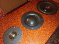
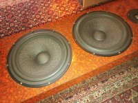
The idea is the following, for the project I will use two 3-inch full-range speakers with an amplitude that reaches a maximum of 90 or so on the smaller speakers. I also have two 6-inch full-range speakers, which will be the main ones. The 6-inch speakers they are a bit more special and I liked them from the very beginning and I definitely wanted to use them, especially since they have 96db amplitude. Now the idea is that I have no idea how the 4 full range loudspeakers will behave together, but I I go by the principle that they should complement each other in frequency response due to the fact that both have a very linear frequency band in theory at least. I plan to use them to create a slightly stronger sound with them, especially for music techno and electro.3-inch speakers have a resonant frequency of 65hz, while 6-inch speakers have a resonant frequency of 40hz.

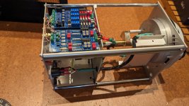
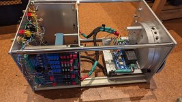
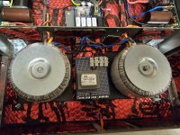
As I said above, I plan to use the loudspeakers for stronger music, not necessarily of high power but of high intensity, both loudspeakers are very capable, they have been tested and I have bought amplifiers for them, as well as most of the materials,it can be called a boombox type project which I want to use in my personal space.I also have the power supplies for the amplifiers, and amplifiers for them, so for the most part I have most of the materials almost ready.

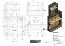
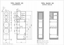
For starters, I'm thinking of going with the resonant frequency of the speakers and the recommended volume at least for the 6-inch ones (approximately 22 liters).
So far I haven't simulated anything in WinISD because I wanted to find out some opinions and possibly discuss them, anyway I plan to make the project when they are all calculated and when I have the rest of the materials.

It will not be a problem for me the space that I will allocate to the enclosure, as long as it is not absurd.
I think that the 6-inch speakers, because they will be bigger, might cover a little bit of the smaller 3-inch speakers, but I don't think that will be the case entirely.
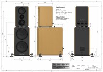
I'm planning to make a single enclosure, which I will possibly insulate with acoustic material, or acoustic sponge, or mineral wool, anyway, it remains to be seen, I'm not completely decided.

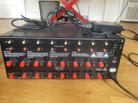
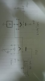
The loudspeakers will have frequency controlled by amplifiers from a 10-band equalizer module, which will directly equalize the frequency given by the amplifier.
As volume control (gain) of the amplifiers, I will use a volume module in 12 steps with equal loudness.I could consider using the iso-barik principle for one of the speakers, to increase the amplitude, but everything I talk about in this thread will remain at the idea stage, which I may complete in a certain period.
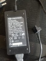
I have already bought the speakers, amplifiers, power supplies, and modules and I will leave you a link below to the materials I will use.
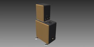
the enclosure remains to be calculated and designed - not being calculated and developed, I have some idea for the enclosure and I was thinking of trying an enclosure with inverted bass speakers

Here are the materials I will use, already purchased:
-6 inch full range speakers (https://www.aliexpress.com/item/100...order_list.order_list_main.101.165e1802vVdWPb)
-3 inch full range speakers (https://www.aliexpress.com/item/100...order_list.order_list_main.232.165e1802vVdWPb)
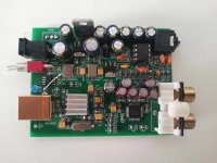
-the equalization module in 10 bands (https://www.aliexpress.com/item/329....order_list.order_list_main.38.165e1802vVdWPb)
-the amplifier for the bigger speakers (50w) (https://www.aliexpress.com/item/100....order_list.order_list_main.60.165e1802vVdWPb)
-the amplifier for the smaller speakers (25w) (https://www.aliexpress.com/item/100....order_list.order_list_main.96.165e1802vVdWPb)
-oxygen-free copper cable of 400 cores (https://www.aliexpress.com/item/100...order_list.order_list_main.284.165e1802vVdWPb)
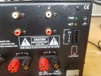
-binding post terminals( https://www.aliexpress.com/item/100...order_list.order_list_main.333.165e1802vVdWPb)
-volume potentiometer with loudness in 12 steps (https://www.aliexpress.com/item/100...order_list.order_list_main.278.165e1802vVdWPb)

I am waiting for some possible ideas for how I could design the enclosure and other suggestions for the enclosure are welcome.
I listen to music genres from electro, techno to hardcore techno and other genres, but I want this project to be a more serious one, so I'm waiting to exchange some opinions and suggestions about how I could make the box and what resonance would be preferable to either, and if I could improve something else in the speaker. I don't think of using filters for speakers precisely because each speaker reproduces its frequency band without being affected by each other and complementing each other.I can allocate enough volume for the smaller speaker boxes, and since the speaker itself will be a single enclosure, it will basically be individual speaker boxes in a single box.. I know it sounds complicated...
The speaker parameters can be found on the products page

I need help with RPi

Hi all, I have been trying to get my raspberry pi working for almost a year now and, apparently, I am a total computer idiot.

I have tried everything that’s been recommended but I’m more confused now than I ever have been and need someone I can send the raspberry pi to to fix it up.

Anybody willing to do that? I sure appreciate it.

Universal Buffer achieving -140 dBc (0.00001 %) THD

Meet the Universal Buffer: A reference class analog preamp, made in Canada.

The Universal Buffer is an ultra high-end stereo analog subsystem. Each channel of the Universal Buffer features a differential input (which, by jumpers, can be configured as a single-ended input), and provides a buffered differential output and a buffered single-ended output. Its gain can be changed from the default 0 dB (unity) by adding a resistor. Furthermore, it can be configured for signal inversion.

The reference class performance of the Universal Buffer is exemplified by its 137 dB dynamic range, abysmally low distortion (including intermodulation distortion), ultra-low noise, 130+ dB channel separation, high common-mode rejection ratio, as well as its ability to drive significant cable capacitance cleanly. All measurements of the Universal Buffer support my claim that this buffer is sonically transparent, and that any contribution to the sound quality made by the Universal Buffer is orders of magnitude below the audible threshold.

The Universal Buffer was primarily conceived as one piece of a reference class preamp. For example, a volume pot followed by a Universal Buffer would form a simple one-input preamp with both differential/balanced and single-ended/unbalanced outputs. Add another Universal Buffer upstream of the volume pot to add a differential input.
Similarly, the Universal Buffer can be used to add a differential input or output to your existing source or load, thus, it completely replaces my previous THAT Driver and THAT Receiver circuits.

Except for the connectors, the Universal Buffer is all surface mounted components. Furthermore, two of the ICs have exposed pads under the IC package, thus, are challenging to solder. A good connection is needed for good performance. Due to this, I will only be offering the Universal Buffer as a fully assembled module.

The first batch of Universal Buffer boards is in production. I expect to have the boards in stock and ready to ship by January 20th, 2020. I have opened up for preorders. I will offer volume discounts for order quantities of 3+, 5+, and 10+.

For the full specifications and to preorder your Universal Buffer, please follow this link: Universal Buffer – Neurochrome

The image shows the final prototype. The production version will be identical, except it will be Neurochrome Blue like my other boards. The circuit design, PCB manufacturing, and PCB assembly were all done in Canada.

Tom

Attachments

  • UNIBUFF_Proto_1p1.jpg
    UNIBUFF_Proto_1p1.jpg
    452.6 KB · Views: 5,016
  • UniBuff_ Distortion Residual (1 kHz, 2 V RMS, UNBAL-UNBAL, 256k FFT, 8 averages).PNG
    UniBuff_ Distortion Residual (1 kHz, 2 V RMS, UNBAL-UNBAL, 256k FFT, 8 averages).PNG
    45.1 KB · Views: 5,055
  • UniBuff_ THD+N vs Output Level, Supply Voltage (1 kHz, 20 kHz BW, BAL-BAL).PNG
    UniBuff_ THD+N vs Output Level, Supply Voltage (1 kHz, 20 kHz BW, BAL-BAL).PNG
    51.4 KB · Views: 4,649
  • UniBuff_ THD+N vs Frequency (2 V RMS, 60 kHz BW, BAL-BAL).PNG
    UniBuff_ THD+N vs Frequency (2 V RMS, 60 kHz BW, BAL-BAL).PNG
    35.8 KB · Views: 4,609
  • UniBuff_ Multi-Tone IMD (AP 32-tone, 2.0 V RMS, Ref._ 2.0 V RMS).png
    UniBuff_ Multi-Tone IMD (AP 32-tone, 2.0 V RMS, Ref._ 2.0 V RMS).png
    55 KB · Views: 4,573
  • UniBuff_Transient_SE_1n0.png
    UniBuff_Transient_SE_1n0.png
    20.2 KB · Views: 1,836
  • UniBuff_Transient_SE_4n7.png
    UniBuff_Transient_SE_4n7.png
    20.1 KB · Views: 914
  • UniBuff_Transient_SE_10n.png
    UniBuff_Transient_SE_10n.png
    20.4 KB · Views: 850
  • UniBuff_Transient_DIFF_1n0.png
    UniBuff_Transient_DIFF_1n0.png
    15.6 KB · Views: 865
  • UniBuff_Transient_DIFF_4n7.png
    UniBuff_Transient_DIFF_4n7.png
    15.7 KB · Views: 1,052

Looking for a DSP based crossover again. Any experience wit the Peavy VSX 26e?

I have been using a QSC Basis 922az to convert my 3 way stand mount speakers to active. I was able to get two of these very old models on Ebay. The second one is now starting fail and I've been looking for a replacement. I can't find a reasonably priced replacement QSC currently listed on Ebay so I'm looking for other options. The miniDSP Flex 8 would work but it doesn't have analog inputs and is $600.00 and I would still need to add an analog to digital converter to use it. I found the new Peavy VSX 26e being sold for $400.00 to $450.00 but I have no experience with any Peavey products. It is a 2 input 6 output balanced device and would do everything I need. Has anyone had any experience with Peavy products that they would like to share? Any other reasonably priced options you might recommend? Here is a link to the Peavy in question.

https://peavey.com/vsx-26e-dsp-based-loudspeaker-management-system/p/04000110

Toroidal Power Transformers - 500VA, Nuvotem Talema, potted, 2 x 35V secondaries

For sale have 2 units of Nuvotem Talema toroidal power transformers, 500VA, 2 x 35V AC secondaries:

https://sg.rs-online.com/web/p/toroidal-transformers/2238910

The transformers are encapsulated (potted). Primaries are for 230V AC.

If interested, please make an offer.

Attachments

  • Talema_01.jpg
    Talema_01.jpg
    133.6 KB · Views: 93
  • Talema_02.jpg
    Talema_02.jpg
    155.5 KB · Views: 95
Projects by fanatics, for fanatics
Get answers and advice for everyone wanting to learn the art of audio.
Join the Community
507,547
Members
7,876,344
Messages

Filter

Forum Statistics

Threads
405,695
Messages
7,876,344
Members
507,547
Latest member
Rattle_and_Hum