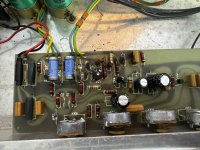
I'm trying to fix this amplifier. Can't find a schematic but I have attached images, it's a pretty simple circuit.
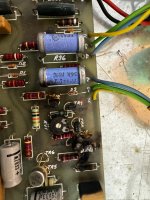
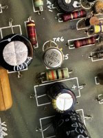
Most transistors were burned and shorted, and there was a shorted zener diode.
I replaced all BC327 transistors with BC328s
I replaced all BC547 transistors with BC546s
I also replaced 3 electrolytics and the shorted zener diode (with a random one i had, no idea what this should be, but it measures similarly to the other non-shorted one in diode mode.)
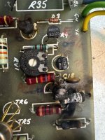
I replaced a burned up resistor with a 4.7k - it was impossible to tell what the old one was but it had one line still intact which was the same as, and was the same size and shape as a nearby 4.7k resistor.
You'll notice a burned film cap next to the other components which i didn't replace as it still measures ok.
On power-up, the MD8003 dual transistor got really hot and started smoking, so i quickly switched it off. This transistor measures fine with my peak component tested (no leakage), however i replaced it with dual 2n2240 transistors to be safe. Sadly - they also heat up rapidly in a few seconds after switching it on.
The amp uses an MJ3001 an an MJ2501, which are both missing - I have them on order but obviously there's a major problem here i need to fix first. I have checked really, really thoroughly for shorts and I cannot find any - I don't know what could still be wrong here. I have tried lifting the resistor I fitted in case it was that, but still the same issue.
Would really appreciate any thoughts.
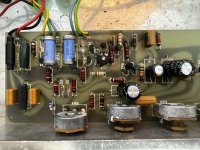
Most transistors were burned and shorted, and there was a shorted zener diode.
I replaced all BC327 transistors with BC328s
I replaced all BC547 transistors with BC546s
I also replaced 3 electrolytics and the shorted zener diode (with a random one i had, no idea what this should be, but it measures similarly to the other non-shorted one in diode mode.)
I replaced a burned up resistor with a 4.7k - it was impossible to tell what the old one was but it had one line still intact which was the same as, and was the same size and shape as a nearby 4.7k resistor.
You'll notice a burned film cap next to the other components which i didn't replace as it still measures ok.
On power-up, the MD8003 dual transistor got really hot and started smoking, so i quickly switched it off. This transistor measures fine with my peak component tested (no leakage), however i replaced it with dual 2n2240 transistors to be safe. Sadly - they also heat up rapidly in a few seconds after switching it on.
The amp uses an MJ3001 an an MJ2501, which are both missing - I have them on order but obviously there's a major problem here i need to fix first. I have checked really, really thoroughly for shorts and I cannot find any - I don't know what could still be wrong here. I have tried lifting the resistor I fitted in case it was that, but still the same issue.
Would really appreciate any thoughts.
Attachments

That 4K7 you fitted, I doubt it would burn up at that value. So the original value is probably much lower. Do you have a good channel to compare against? You might have to resort to reverse engineering the circuit around that area so that you can understand what the values should be.
Last edited by a moderator:
Hey, thanks a lot for the response.
Good point about the 4K7.. I assumed it had maybe been burned more by the neighbouring transistor. Maybe I should try experimenting with lower values.
Sadly no comparison channel available.
Good point about the 4K7.. I assumed it had maybe been burned more by the neighbouring transistor. Maybe I should try experimenting with lower values.
Sadly no comparison channel available.
That “dual transistor” which overheated will likely have its emitters tied together. Where do they go from there? There is supposed to be something that keeps a relatively constant current. Could be a transistor wired as a “current source” which could be shorted. That would cause the overheat. If a high value resistor were used, overheat is unlikely.