Mark Levinson ML10A recap

Hello! Just bought a ML10A as a secondary preamp for my hifi system (using mainly my ML no.26 and a GAS Thaedra). The preamp inside looks totally untouched, and as I supposed when I open the psu cover one of the power supply caps had a leak. The preamp works fine but I have to recap that old machine ! Does anyone have the service manual of it? I search around the net with no hope 🙁 . Do I have to re-adjust something after doing the recap? Best regards!!!

Attachments

  • IMG_1764.jpeg
    IMG_1764.jpeg
    588.5 KB · Views: 159
  • IMG_1763.jpeg
    IMG_1763.jpeg
    543.4 KB · Views: 119
  • IMG_1762.jpeg
    IMG_1762.jpeg
    431 KB · Views: 111

Suggestions for Improvement?

Hi All,

I was on this forum years ago and have been building tube audio amplifiers for a while now but am still learning. So I want to share a current project and ask for some suggestions on how I can improve its high-frequency performance.

The backstory:

After a jig of working mainly with small signal tube amplifiers (preamps, phono stages, etc.), I decided to take a stab at a power amplifier with toroidal power and output transformers.

The transformers I purchased were part number VDV-4070-CFB-PPS from Bureau Vanderveen. According to their published specifications, they looked like very good units. Their wide bandwidth is primarily what sold me.

https://www.mennovanderveen.nl/index.php/nl/producten/specialist/vdv-4070-cfb-pps-detail

Having no experience with this kind of transformer, I made the following circuit:

Schematic2.png


Schematic.png

This is a markup of a partial schematic. I only am showing the audio circuit and not the microprocessor control circuitry (as it is not relevant). The markings are what I did to improve the performance already. Purple markings show DC voltages. Red markings are circuit and component value tweaks. Cross-outs are in blue.

Measurements:

All measurements were taken with a an 8-ohm resistive dummy load hooked to the speaker output. Measurements were taken with an H8903B audio analyzer, a Siglent SDS2204X oscilloscope, and a Fluke 287 multimeter. Square wave plots were generated by a BK Precision 4045B waveform generator. VRMS measurements were taken just before the amplifier clipped. Nominal power output is 50 watts into 8-ohms.

1. Open loop frequency vs. gain plot.

FrequencyVRMSGainGain (dB)
20​
16.5462987​
165.462987​
44.3740172​
50​
19.0918831​
190.918831​
45.6169753​
75​
20.0111219​
200.111219​
46.0254288​
100​
19.9404112​
199.404112​
45.9946822​
500​
20.0818326​
200.818326​
46.0560668​
1000​
20.0818326​
200.818326​
46.0560668​
5000​
19.9404112​
199.404112​
45.9946822​
10000​
19.6575685​
196.575685​
45.870596​
15000​
19.0918831​
190.918831​
45.6169753​
20000​
18.243355​
182.43355​
45.2220942​

1698622573071.png


2. Closed loop frequency vs. gain plot along with THD:

FrequencyDistortionAmplitudeAmplitude (dB)
20​
3.15​
21.16​
26.51031327​
25​
0.32​
20.89​
26.3987688​
30​
0.25​
20.91​
26.40708066​
50​
0.23​
20.73​
26.33198604​
75​
0.25​
20.7​
26.31940691​
100​
0.23​
20.67​
26.30680953​
250​
0.24​
20.66​
26.30260634​
500​
0.25​
20.67​
26.30680953​
750​
0.25​
20.66​
26.30260634​
1000​
0.26​
20.66​
26.30260634​
5000​
0.57​
20.52​
26.24354713​
7000​
0.78​
20.42​
26.20111476​
10000​
1.04​
20.23​
26.11991766​
15000​
1.7​
19.7​
25.88932452​
20000​
2.3​
19.2​
25.66602457​
30000​
3.67​
17.81​
25.01327839​
50000​
5.87​
14.37​
23.14913536​

1698622763498.png


1698623444328.png


Questions and Observations:

The current driver I am using rolls off open loop starting around 10kHz or so. I observed the tubes are the main contributor to the rolloff and not the transformer. So naturally the GFB loop, when introduced, increased the gain more at higher frequencies with respect to the lower frequencies. Distortion increased due to the higher gain. What do you suggest I do to improve the performance of the open-loop bandwidth? Are there better driver circuits I could look at using?

I have more questions but will save them for another post.

Thanks very much.

Driver selecton help.... Small Open Baffle with Faital Pro 15PR400

I have a new pair of Faital Pro 15pr400 4 Ohm that I bought for a different project, and am now wondering if I should sell them, or make something new.

I was interested in the idea of making a "small" open baffle with them, using minidsp for the crossover, to be played at low to mid levels.

Anyone have any suggestions for a tweeter to match with? I want to keep it relatively simple and small.

I am aware of this... but it doesn't interest me...

OBL-15

I was thinking maybe a BG Neo 3 (or 8), maybe a Aurum Cantus G3Si, maybe Heil AMT... open to ideas!

Thanks.

Dynacord PowerMate 1600-3 & KV2 Audio ESD15

Hello everyone,

I have recently purchased Dynacord PowerMate 1600-3. Can someone please tell me this mixer would work well (or maybe not at all) with KV2 Audio ESD15? Here are the basic specs for both:

1. Dynacord PowerMate 1600-3

2x 1000 W/4 Ohm RMS
2x 600 W/8 Ohm
2x 1350 W/2.7 Ohm
6 Mic/Line XLR inputs with 3-band semi parametric EQ
4 Mic-/Stereo line combi-inputs with 3-band-EQ
2x 24-Bit stereo effects processor with fixed presets, plus editable and storable user presets
2x FX/AUX for internal effects device
2x AUX Pre/Post switchable
2x Monitor AUX (pre)
Mute per channel
Switchable 80 Hz low-cut
Switchable Voicing Filter per XLR input
Feedback filter for MON 1-2
New 11-band EQ routed to the master channels
B-Master output for recording or mono subwoofer, etc
USB Interface for music playback or output for recording applications (up to 4 tracks at the same time)
Integrated Midi interface in/out
Switched-mode power supply
Integrated loudspeaker protection
Speaker Twist outputs
Volex mains input

2. KV2 Audio ESD15

2.1. System Acoustic Performance
Max SPL Long-term 126dB
Max SPL Peak 132dB
-3dB Response 48Hz to 18kHz
-10dB Response 45Hz to 28kHz
Recommended Power 500W
Sensitivity 97dB
Impedance 4Ω
Crossover Point 500Hz, 2.5kHz

2.2. High Frequency Section
Acoustic Design Horn Loaded
High Horn Coverage Horizontal / Vertical 80° x 60°
Throat Exit Diameter / Diaphragm Size 1" / 1.75"
Diaphragm Material Nitride Titanium
Magnet Type Neodymium
Protection Electronic RMS and Peak Limiter

2.3. Mid Range Section
Acoustic Design Horn Loaded
Mid Horn Coverage Horizontal / Vertical 80° x 60°
Woofer Size / Voice Coil Diameter / Design 6" / 1.5"
Diaphragm Material Epoxy Reinforced Cellulose
Magnet Type Neodymium
Protection RMS Limiter

2.4. Low Frequency Section
Acoustic Design Front Loaded, Bass Reflex
Woofer Size / Voice Coil Diameter / Design 15" / 4"
Diaphragm Material Epoxy Reinforced Cellulose
Magnet Type Neodymium
Protection RMS Limiter

2.5. Speaker Input
Speaker Input 2x Neutrik Speakon®, Terminal Block

I am also open to suggestions for any other 3-way passive loudspeakers. They would be used in small indoor and outdoor settings.

I appreciate any advice!

Rufad

I have a passive subwoofer need low pass filter

So I am thinking to connect 220uf capasitor it might block high and allow low frequency to pass


My subwoofer specs
Bass Enhancer, Flat Cap. 5,25 Inch Low frequency (40Hz to 160Hz) driver with Amplifier sub out/Low pass filter connection. Full Range Driver with 15W direct Car Head output. 6.5cm depth required to use in car door pad. Best for home theatre stock driver

For Sale Genuine Tripath evaluation board RB-TA3020 with power supply PCB

Hello I have 3 Tripath evaluation board RB-TA3020 for sale at 76€ if you need power supply pcb
Included Sanken rectifier bridges and connectors is 18€.
Here populated power Supply shown as an example
Tracked shipment shipping to US on request.
Payment by paypal
1670165426830.jpg

Attachments

  • 1670165426826.jpg
    1670165426826.jpg
    462.2 KB · Views: 154
  • 1670165465030.jpg
    1670165465030.jpg
    476.5 KB · Views: 134
  • 1670165465023.jpg
    1670165465023.jpg
    403.6 KB · Views: 142
  • 1670165426819.jpg
    1670165426819.jpg
    433.9 KB · Views: 147

diyAudio-store offline

I cannot reach your site today -- anything "untowards" happening?

$ dig diyaudiostore.com

; <<>> DiG 9.18.12-1ubuntu1.2-Ubuntu <<>> diyaudiostore.com
;; global options: +cmd
;; Got answer:
;; ->>HEADER<<- opcode: QUERY, status: NOERROR, id: 48071
;; flags: qr rd ra; QUERY: 1, ANSWER: 1, AUTHORITY: 0, ADDITIONAL: 1

;; OPT PSEUDOSECTION:
; EDNS: version: 0, flags:; udp: 512
;; QUESTION SECTION:
;diyaudiostore.com. IN A

;; ANSWER SECTION:
diyaudiostore.com. 300 IN A 23.227.38.65

;; Query time: 52 msec
;; SERVER: 8.8.8.8#53(8.8.8.8) (UDP)
;; WHEN: Mon Nov 13 15:46:20 EST 2023
;; MSG SIZE rcvd: 62

$ date
Mon Nov 13 03:47:21 PM EST 2023


There was a problem loading this website
Try refreshing the page.

If the site still doesn't load, please try again in a few minutes.

Refresh Page

Elekit TU-8100 project

Hello,

New member from Italy. A friend of mine purchased an Elekit TU-8100 kit from a japanese ebay vendor, instructions in japanese. He never got around to building it. He proposed to sell the kit and I accepted. He works elsewhere, so he will bring the item in a couple of weeks or so.

In the meantime have been browsing this forum and I found tons of useful information.

I have already bought two fostex full range desktop speakers, P800E, I received and assembled them. That was easy

I have no experience at all on building a vacuum tube amp. I studied on several sources online, I bought soldering kit, 0.5 mm 63/37 solder, magnifying glass with led lamp, tools. I also found a video where a Canadian man builds the amp with japanese instruction. So I studied the video.

But the instructions are in japanese. I'm a bit worried. I was wondering if some of you who built this amp could take a picture of the english instructions and private message me.

I fear that this request could come across as unfair to the north american Elekit dealer because this friend of mine bought the kit in Japan. If it is so, i do apologize. But I'm a newbie and are a little bit uneasy.

Sorry again if the request offended someone.

Regards,

Patrizio.

VFET-X (or my 1/3 40th Anniversary Sony VFET Clone)

I always wanted to build a last special amplifier, and wanted it to be big and spectacular.
My big example is the '40th Anniversary Sony VFET Amplifier' Nelson presented at CES in 2014.
There are more members who told me they also want to build something like this so I opened my first thread 🙂
I will post a lot of pictures...
What I like to try is building a stereo version of this amp with 1/3 of the VFET's so 8 per channel instead of 24.
Then bias each a bit higher to get a 1/2 40th Anniversary Amp😀

The schematic is the original Sony VFET pt2 article with the two VFET's paralleled and then double it to get a fully balanced amp.
Both sides are connected with R24 to each other instead of to ground.

I will make my own PCb's, chassis and so on, just having a lot of fun.

On Ebay I found this nice Pass like heatsinks, so I will build the whole amp in a kind of XA160 chassis.
The heatsinks are 'Oxidised' according to the seller, is that different to 'Anodised'? Does somebody know?
They feel different and look more shiny than what I'm used to.
I tested one heatsink with around 100 Watts on the surface, but the surface was too rough, brushed, to get good results. After removing the black 'oxidized' layer and a lot of smooth sanding they transfer the heat better.
I estimate each heatsink can do about 80 Watts of heat. I have six of them so total of 480 Watts. I hope 😱

Attachments

  • 40yearBIG.jpg
    40yearBIG.jpg
    284.5 KB · Views: 3,577
  • Big-Sony-DIY.jpg
    Big-Sony-DIY.jpg
    133.3 KB · Views: 3,508
  • NG7_Pass_VFET.jpg
    NG7_Pass_VFET.jpg
    251 KB · Views: 3,612
  • sinks-arrived.jpg
    sinks-arrived.jpg
    325.6 KB · Views: 3,286
  • sink-top.jpg
    sink-top.jpg
    200.7 KB · Views: 3,142
  • sink-brushed.jpg
    sink-brushed.jpg
    244.8 KB · Views: 1,057
  • sanded.jpg
    sanded.jpg
    251.1 KB · Views: 1,247
  • heat transfer.jpg
    heat transfer.jpg
    297.7 KB · Views: 1,455
  • 100Watt.jpg
    100Watt.jpg
    311.7 KB · Views: 1,379
  • after-sanding.jpg
    after-sanding.jpg
    376.3 KB · Views: 1,057

Layout of crossover help please

I have a crossover schematic and also have the parts on hand. Its a 2 way design. Crossover will be mounted on a wood board and soldered underneath for looks. I want to put both the HF and LF crossover on same board if possible.

I need some help in the layout. I know to keep the inductors at angles if they are close.

Looking for something that visually looks good also.

I can post the schematic if needed.

Thanks!!

Driving Active Speakers from a Behringer Powered Mixer PMP560M

I have active speakers that I need to use with a powered mixer ( Behringer PMP560M). It has no signal outputs but I suspect that the output maybe BTL. Therefore the usual circuits are no good as they are designed for a traditional single ended amp & will short a bridged amp.

Before I tackle the detailed design work, has anyone seen or designed such a circuit?

For Sale 985 NOS International Rectifier IRFP9240 P-Channel MOSFETs

SOLD

These have been in storage for 20-ish years and some of the antistatic tubes have yellowed. There are 39 tubes of 25 pieces, plus another partial tube of 10.
Listing these as a lot for $1000 in the off chance someone has a really BIG project, or wishes to create matched sets for resale.
IRFP240 (N-Channel) ones are in a separate listing.
20231108_080515.jpg

20231108_080549.jpg

20231107_081127.jpg

20231107_080522.jpg

For Sale 1,400 NOS Fairchild IRFP240 N-Channel MOSFETs

SOLD

These have been in storage for 20-ish years and some of the antistatic tubes have yellowed. There are four boxes of 300 pieces, plus another 200 in loose tubes.
Listing these as a lot for $1000 in the off chance someone has a really BIG project, or wishes to create matched sets for resale.
IRFP9240 (P-Channel) ones are in a separate listing.
20231112_155003.jpg

20231112_155021.jpg


20231112_155206.jpg

20231112_163127.jpg

Affordable Ferrofluid for Canadian DIY folk

It all started with tearing down and rebuilding a set of beautiful old KEF 104.2's (with questioning side-glances at my Ditton 44's)...

Care to help me test-run a brand new website that is set to distribute ferrofluid at an affordable rate in Canada come Dec.?

I hope that this is not verboten on this forum; if it is, I'll understand and remove it with apologies...

I've created this site myself, with potentially questionable editing skills, so any positive feedback would be appreciated.

www.speakerferrofluids.com

For us DIY Canucks, accessing ferrofluid to rebuild drivers is practically impossible / unavailable in-country (which is bizarre) unless we ship drivers to technicians to do the work for us. I communicated with speaker repair shops in Vancouver, Montreal and Toronto ~ if I was not keen to send them my drivers for repair, they did not seem at all inclined to send me ferrofluid to do it myself...

Ferrofluid is absurdly expensive to bring in from elsewhere; case in point; today's currency conversion rate ($1.00 USD = $1.38 CAD) / ($1 EURO = $1.48 Canadian Dollar) and shipping costs for ferrofluid makes it somewhat akin to liquid gold! All of the several dozen sources that I looked at in Europe and America were more than willing to send ferro' to Canada, but only via courier or some expensive version of Royal Post :-(

This situation finds those here in the Great White North facing invoices of roughly $60 CAD to receive very small packets of ferrofluid!

In partnership with the world's largest ferrofluid manufacturer, Ferrotec ~ who have been great to deal with, my plan is to change this foolishness... come Dec., DIY Canucks can rejoice at access to affordable ferrofluid products, shipped nationally.

Thank you in advance for your input.

Andrew Drouin


BTW: Oddly, Bit Defender gives SSL warnings with I load the website with Microsoft Edge, while both Google Chrome and Firefox load it flawlessly... Something to look into going forward, prior to the Dec. roll-out.
  • Like
Reactions: rsavas

First Watt M2 Noise

I am getting some noise from my First Watt M2. It is noticeable on higher frequency compression drivers on a 800 hz. cutoff horn. So, the driver is VERY efficient and I don't think this noise would even be noticeable on typical efficiency speakers. But, high efficiency is what I use. I tried plugging the M2 into a power conditioner and no change. I don't think it's power supply hum, it's too high frequency. I also allowed the amp to warmup for several hours.

I have read about using a resistor and L-pad to bring amps up out of a noise floor. I do not know how to design this. Anyone tried anything like this with the M2? Any tweaks?

I love the amp and I fully embrace the zero feedback Class A design, so this is not a criticism in any fashion.

Cheers,

Jamie

For Sale A pair of 801A DHT tubes

SOLD NOW
A pair of National Electronics 801A from the same lot number, in their original larges boxes.
185USD shipped to most parts of the world registered+tracking. PayPal FF only please.

Attachments

  • 20231112_112937.jpg
    20231112_112937.jpg
    331.5 KB · Views: 74
  • 20231112_113012.jpg
    20231112_113012.jpg
    422.5 KB · Views: 71
  • 20231112_113130.jpg
    20231112_113130.jpg
    277.4 KB · Views: 82
  • 20231112_112627.jpg
    20231112_112627.jpg
    384.9 KB · Views: 81
  • 20231112_112813.jpg
    20231112_112813.jpg
    410.9 KB · Views: 85
  • 20231112_112700.jpg
    20231112_112700.jpg
    331.2 KB · Views: 79
  • 20231112_112654.jpg
    20231112_112654.jpg
    252.4 KB · Views: 80

SB17CAC35-8 and SB26ADC-C000-4 two way project

Hi everyone,

I'm planning to build a set of bookshelf speakers using the SB17CAC35-8 midrange driver and the SB26ADC-C000-4 tweeter (+wave guide), cross at ~1300 Hz. My goal is to build speakers that sound clear and crisp in the mid/high-frequency ranges for casual acoustic music listening in a medium/small-sized room. This time, I've decided to invest more time and effort into planning and building the right enclosures. The speakers will be connected to a Topping PA5 II plus 4Ω amplifier.
I have a few questions that I hope you can help me with:
  • I used WinISD to simulate the box volume and tuning frequency. Can you please take a look at the attached screenshots and let me know if there are any issues with the box design?
  • Do the cutoff and tuning frequencies make sense for a pair of speakers?
  • Do I still have some low frequency to enjoy?
I'm planning to tune the box to 60Hz with a volume of 15 liters and a high-pass filter cutoff frequency of 80Hz.

I will keep updating this thread

Thank you for your help!

Attachments

  • air_velocity.png
    air_velocity.png
    11.2 KB · Views: 134
  • cone_excursion.png
    cone_excursion.png
    10.7 KB · Views: 158
  • filter.png
    filter.png
    2.8 KB · Views: 132
  • portgain.png
    portgain.png
    8.7 KB · Views: 133
  • SB17CAC35-8 .png
    SB17CAC35-8 .png
    225.2 KB · Views: 134
  • SB17CAC35-8 specs.png
    SB17CAC35-8 specs.png
    102 KB · Views: 137
  • SB26ADC-C000-4 specs.png
    SB26ADC-C000-4 specs.png
    79.2 KB · Views: 132
  • SB26ADC-C000-4.png
    SB26ADC-C000-4.png
    197.3 KB · Views: 139
  • tfm.png
    tfm.png
    9.5 KB · Views: 146
  • Screenshot 2023-10-31 at 20.54.37.png
    Screenshot 2023-10-31 at 20.54.37.png
    65.7 KB · Views: 153
  • Screenshot 2023-10-31 at 20.54.43.png
    Screenshot 2023-10-31 at 20.54.43.png
    37.3 KB · Views: 162

Schematic diagram for Mordaunt-Short MS309-W

Can anyone supply, or tell me where I can get, a schematic diagram or Service manual for the above, please. A U.K. source for spares would also be helpful.
The 1.6AT fuse in the mains input blows in one I'm trying to repair, and none of the usual suspects(Rectifier, Filter Capacitors, etc.,)are faulty. Prior to the fuse blowing, the amp. would cut out if the volume was advanced more than about 60%, with only a 'signal' from my finger on the line level i/p present
Could the mains transformer have shorted turns??

Exploring the Toshiba 2929 Audio IC - Seeking Guidance

Greetings fellow audio enthusiasts,

I hope this message finds you well. I must admit that starting this new thread feels a bit daunting, but I'm excited to share my new journey with you all. For those who have followed my previous thread, you might remember that I'm on the spectrum (autistic), and this community has been an incredible source of support and knowledge as I delve into the world of audio electronics.

My journey began with a simple question about the AX11 from Apex, but it quickly became apparent that my understanding of transistors, biasing, and even basic electronics was sorely lacking. It's as if I tried to play a 7-string guitar without knowing what a mode or scale was - and trust me, it didn't end well.

This time around, I reached out to an old friend who's been a guiding light on almost my entire life. He kindly reminded me not to put the cart before the horses and promised to send me something to kickstart my learning process. A few days later, a package arrived, and despite its size, it contained only a couple of ICs. I couldn't help but wonder what I was supposed to do with them.

Inside, I found a note from my friend: "Figure it out for yourself; it's not rocket science." He certainly has a knack for sharp humor. So, what did he send me? Well, you probably guessed it from the thread's title - a couple of Toshiba 2929 ICs.

I dove headfirst into researching this mysterious component, only to find a not-so-user-friendly datasheet and a distinct lack of audio amplifier schematics using it. It seems that some datasheet writers forget that not everyone is on the same level of understanding.

Now, while I understand this isn't rocket science, I still find myself in need of some guidance on this less popular audio IC. Supposedly, it's a 45W 4-channel grail (according to my friend), with THD as low as 0.007% and PNP/NPN DMOS output. Has anyone had any experience with this little unknown gem?

My goal is to build something with it and learn along the way. However, I'm stumped when it comes to deciphering the capacitor and resistor values. This leads me to question once again who might have authored such a confounding datasheet.

So, I turn to this wonderful community for assistance. Can anyone shed some light on the component values and guide me on how to connect two unbalanced inputs to produce four channels? I have a hunch that it's possible, but I'd greatly appreciate any insights you can share.

Thank you in advance for your support and expertise. Let's embark on this new adventure together.

Warm regards

Attachments

Tamura Iron, Sakuma Phono

Selling some Tamura items from my collection in excellent to new condition:

1x pair TKS-27 step-up transformers: 0-150-200-300 : 100k 450€/pair
1x pair A-4714 output transformers: This is a very interesting one, as it can be used as line output or speaker output. Primary 5k, 60ma / Sec. 600ohm CT, 6ohm. 650€/pair
1x pair A-342 interstage transformers : 5K:5KCT, 30ma 450€/pair
1x pair A-394 chokes: 30H, 40ma (NIB) : 375€/pair

1x stereo set parts for Sakuma phono EQ: 2x VL207 variable inductors (0.5H-5H,7ma), 2x 0,033uf Duelund Cu-Sn, 2x 0,047uf Duelund Cu-Sn, Kiwame 10k, 3k x2. Resistors and capacitors are new and unused. Have a new pair of Duelund Cu-Sn 0,47uF to finish off the EQ module if needed (depending on which Sakuma phono schematic you want to build). 250€ for the set

Will consider offers and discounts for multiple items
Items are in Belgium, will ship worldwide

Attachments

  • IMG_3655.jpeg
    IMG_3655.jpeg
    344.3 KB · Views: 171
  • IMG_3656.jpeg
    IMG_3656.jpeg
    327.3 KB · Views: 156
  • IMG_3657.jpeg
    IMG_3657.jpeg
    281.9 KB · Views: 140
  • IMG_3658.jpeg
    IMG_3658.jpeg
    268.2 KB · Views: 143
  • IMG_3659.jpeg
    IMG_3659.jpeg
    339.4 KB · Views: 157
  • IMG_3660.jpeg
    IMG_3660.jpeg
    415.1 KB · Views: 151
  • IMG_3661.jpeg
    IMG_3661.jpeg
    354 KB · Views: 168

Weird ground loop

Hi guys, I recently build a DAC using the Xingcore U30 as I2S interface. I chose to feed it using a linear PSU regulator which shares the ground with the PSU reg that feeds the DAC itself. Connecting the USB input to my Intel NUC8 triggers the ground loop, which disappears when I disconnect the USB cord. Another fact is that when I connect my laptop in battery mode to the DAC, the ground loop is absent. What could it be? Can you suggest some possible workaround?
PXL_20231029_141439305.jpg


Thank you all and regards,
Gaetano.

Can you help identify this Xover?

Found this, is it a speaker Xover?

I am not familiar with this type of transformer- they have four leads on each "side", two of which are twisted together. Looking at the circuit I can't positively identify where a ground would be connected. The board as a unit has six leads, all are color coded differently.

Are these caps polystyrene? Is "NPC" a brand name or a type? Would the red tipped ends be for positive polarity?

Is this board is for a stereo hookup, with two identical channels? Or are these in parallel?

I'm just being curious and wanting to learn about components and how to test this circuit for fun.

Thanks,
Keith

xover_9016.jpg


xover_9015.jpg
xover_9015.jpg

Advanced Passive Xover circuits

Hello all,
i cant understand what exactly those ciruits (R3/R5/R4 and R6) are. These are above my low passive xover circuits knowledge.
I see a impedance peak circuit LCR, i see a bandpass second order. but what do those R values ?
It looks like that each of the first part of the second order xover in the bandpass was combined to an Contour Network Circuit (RC/RL>R5 and R3 up/down)
is that correct ?
And for the R4 and R6 i have no clue what kind of combined circuit this is.
Anyone able to enlighten me ?
Unbenannt.JPG

What's the issue in this 300B amp LTspice simulation

I posted a thread about how to simulate the output transformer, and how the circuit is working. But during the simulation, the output occurs clip at the negative half wave, I'm not sure why it happens.

I drew this diagram based on luxman mq300 manual and it's internal photo, the intention is to learn how this circuit works. Most of the values I think they are correct but some of them based on my limited knowledge.(R1, C6, R7, and all plate voltages).

Attachments

P600x4 keep blowing same channel

Hi all,
I have a p600x4 that keeps blowing the mosfets on the right rear channel. Both npn and pnp.

It has also taken out the collector .5 ohm surface mount resistor 2 times.

I have replaced all of the parts only for it to randomly fail on the same channel again.

It can last 5 minutes or a week before failing again. I am at a loss. Please help

Thanks in advance

PS Sizing

I would like to know how the transformers in the PS are sized.
So far, all the information that I could find is related to the voltage requirements, but I would like to address the requirements for the current, more specifically, the inrush current.
There isn't enough information on the subject. What is the largest inrush current that a transformer could handle given that the diameter of the wire in the windings is Xmm?
How is this calculated? Or the transformer is designed to handle a specific amount of current during normal operation and the inrush current isn't an issue, no matter how large the filter capacitors are?
Thanks in advance.
Best
Soundork

Valve PA amplifier - what to do with it?

IMG_20230928_184428895_HDR.jpg


IMG_20230928_184443145_HDR.jpg


IMG_20230928_184912373_MFNR.jpg


IMG_20230928_184922688_MFNR.jpg


IMG_20230928_184929713_MFNR.jpg


IMG_20230928_184934525_MFNR.jpg


IMG_20230928_184941117_MFNR.jpg


IMG_20230928_184906615_MFNR.jpg


I have a valve PA amplifier which has been my possession for many years. It was my late grandfathers. I've never seen it working. It's complete but would obviously need a fairly comprehensive overhaul before it could be used. The valve line up is EL34, EL34, ECC81, 6BR7, 6BR7, ECC82. There are 2 EZ81 rectifiers also.
It's an strange old thing which has the option of running from a 12v battery. It has a wierd mains/battery socket on the front. I think it looks pretty cool and would love to use it as a guitar amp and build a little cab for it to sit on top of, finishing both the amp and speaker cab in a matching quilted leatherette similar to the beaten up stuff that's already on the amp casing.
Whatever happens, it stays as it looks now. It won't be cannibalised for parts!

The issue is that I can't find a schematic for it. I've looked many times over the years and come up with nothing.
Searching on Google just brings up old posts on vintage-radio, (one of which was made by myself), another gives some interesting background info on the company who made it. However there's no schematics posted anywhere.
If I had a diagram to follow I'd be able to make better sense of the circuit but as a relative beginner, it's beyond my capabilities to trace out the entire circuit.

So, I'm thinking of just starting from scratch and finding a suitable guitar amp schematic which uses the EL34's and rewire it that way.
I've no use for the 12v circuitry etc...

I'm thinking a good starting point would be to make sure the transformers work, these being the most expensive things to replace.

If anyone can suggest a guitar amp that could be make use of as many of the existing components as possible, let me know.

Any ideas on how to precede will also be welcomed!

Any Proceed Amp 5 Owners?

I have a favor/question to ask.
Recently I purchased one of these amps locally. Upon going to replace the fuses I have noticed there are two different fuses in my unit in locations F500, F501 and F502. In F502 is a 5 amp fuse while F500 and F501 have 10 amp fuses. If anyone owns this amp, could you possibly pop it open to verify if that is correct? Thank you for your time.

Luxman L58A

I'm making the adjustments to finish setting this amp up and want to check my understanding of the procedures before I do (see attached photo for the Luxman procedure)

Firstly I wanted to check the idle current so I pulled the fuses and connected my meter across the fuse holders and switched on, set this on both channels to 200ma as its on a bulb limiter, is this about right?

Now DC offset adjust it says to earth the test point to whichever channel I'm adjusting, I take it just clip a lead between TP and Chassis? Then follow procedure?

And the AVR adjustment, cannot find the test points what am I adjusting here?
Screenshot_20231107_115045_Adobe Acrobat.jpg

Good power supply for MayFlower O2 ?

I recently bought a Mayflower O2 headphone amplifier which comes with a Triad WAU12-200 (12VAC 200mA) power adapter.

I contacted MayFlower and they said that the PSU(WAU12-200) is more than enough. I also contacted JDS Labs and they said that with WAU12-200, under heavy use, the amp causes distortion and the failure rate also increases. JDS Lab says the 15VAC power adapter they sell on their website is the best.

NwAvGuy himself says on his blog that WAU12-200 is adequate in 99% of cases but when using power hungry low impedance headphones (HifiMan Planars), the ideal power adapter would be rated at 14 - 16 VAC and 400 mA or higher. He recommends WAU16-400, 412-218054 or WAU16-1000 .. but again some people say that this is outdated information.

These are thee headphones I have(or will purchase in the future):

AKG K702/Q701
Senn HD58X
DT990 250ohm
Philips X2HR
AD900X
Grado SR225i
HE-400 (the very old one)
T50RPMKII
Deva Pro
Sundara
etc....


Should I stick to my WAU12-200, Should I get the 15VAC adapter from JDS Labs or should I get one the WAU16's ?

Rotel RCD-855 / CDM4/19 broken spring

I just bought a 2nd hand Rotel RCD855 with cmd4/19 transport.
After unpacking the drive wouldn't open (just a few cm). I opened the cdp and noticed the spring was loose in the case. I also found a broken pin. (see photo).
Probably damage from postage, because the seller was original owner and seems pretty trustworthy.
Anyway, looking for instructions/help how to fix this.
  • how to disassamble the transport to get to the point where I can reach the spring
  • how to fix the broken part, is there a replacement pin or are there any other fixes ?
Any help appreciated.

Attachments

  • RCD855-broken pins.jpg
    RCD855-broken pins.jpg
    809.3 KB · Views: 147
  • RCD855-inside1.jpg
    RCD855-inside1.jpg
    560.5 KB · Views: 201
  • RCD855-inside2.jpg
    RCD855-inside2.jpg
    343.3 KB · Views: 138

Shallow speakers for home theater

Hi all,
For my first post, I would like to first thank for all the contributors to this forum. All the info in here is gold, thanks!
Also, sorry in advance for the length of the post.

Now what brings me here. I would like to setup a home theater in the coming year, and would love to have shallow speakers, that can play nicely above 80Hz (I will use subwoofers below that).
My requirements for the speakers:
1. shallow speakers, ideally 10cm or less. I don't care about height/width though.
2. wide enough dispersion for all listeners to comfortably enjoy the movies.
3. SPL wise, I am targeting around 80-75 dB average for each speaker at each seat, and some headroom of ~15 dB SPL.
4. All speakers will be eq-ed (if that is a word) using dirac/audyssey. So I am not necessarily looking for a specific frequency response profile out of the box, just enough distortion-free output and eq-ability.
5. Easy enough to build for a first set of speakers. I am a decent woodworker, but have no experience with speaker building (e.g. no knowledge of crossovers).
6. I am looking at building 11 speakers and 4 subwoofers. So cost wise, would be nice to keep it under 150 per speaker.
7. All speakers will be on-wall.

I looked at commercially available options, and it seems they are all out of reach pricewise (e.g. Grimani systems Rixos-S and Ascendo 6).

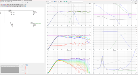
Looking around the forum, it seems there are quite a few positive review of Markaudio drivers, and they seem to fit the bill, however I did not find reference builds there with a "shallow enough" design. I hence tried the following design under winISD:
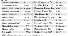
  • CHR-90 or CHP-90 for front speakers. Those are the farthest from listeners and would require the most output and smallest angle to cover. These drivers seem efficient enough and should provide the SPL levels / dispersion desired.
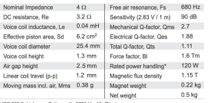
  • CHR-70 or CHP-70 for other speakers. As those are closer, so they will need less output but need to cover wider angles. IIUC, smaller fullrange drivers will start beaming at higher frequencies right? Don't know if those are enough dispersion wise though.
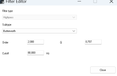
  • sealed cabinets: it seems those drivers are happy in a sealed enclosure when no bass extension is needed.
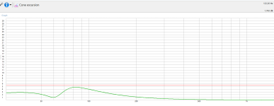
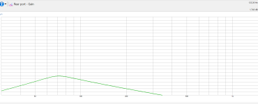
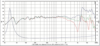
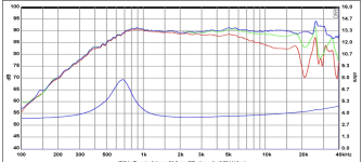
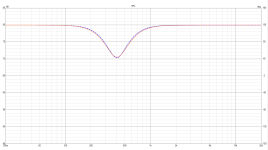
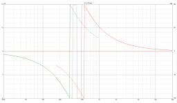
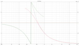
    For the CHR-90, a 7L box has an f3 at 93Hz and an f6 at 70Hz. With 30Watt, it seems to produce enough SPL with 95 db at 3m (and still some headroom left for power and cone excursion). I am thinking this should be enough for my needs, assuming I will also eq them (so some headroom is required I guess), and putting them on-wall should give some gain.
    For the CHR-70, same principe. It seems a 5L box produces the desired level of SPLs (about same f3/f6 as the above).
  • Dimensions: I tried to use irrational ratios (square roots of primes) to get nice shapes. For example, for a 5.5L box I get 26.4cm width, 5.5cm depth and 37.9cm height internal. This is very shallow and I wonder if there could be issues with back panel too close to the driver? Also, what is the advice for such a box wrt bracing?
  • Driver placement: I have not read much about driver placement. Would it make sense to just put it a 1/3rd height, and at center wrt width?

None of the above is fixed (driver choice, dimension, ...) and I am open to suggestions.

Here are extra info on the room, speaker/listeners placement, and some computations I made, if that helps :
- the Room is 5.3m x 3.7m (black spots are seats, blue box is couch, red boxes are speakers, red cones cover 40 degrees angles -- ignore the surround glitch, will fix my script)
1694617957969.png

- Here is a table of speaker/listeners distances (in meters), and the associated attenuation if that helps
1694618079690.png
1694618251764.png


Sorry for the long post... and thanks in advance!

Riddle me this...

I recently finished building my first EL34 single ende tube amp. I must say it sounds rather good. I dare to say it sounds really good. I have had many amps and speakers and also worked in a hifi store for several years. Last weekend I went to a friend of my friend's father who used to be a professional audio technician for several decades and has worked with several great artist along the way. So if one person knows sound, it must be him. He also builds spuikers for a living.

When I took the amp to his place, he was very impressed with the sound. Ofcourse the low end lacks in comparison with a powerfull solid state, but he very much liked the openess, transparency and detail my amp produced. He also said how easy it is to listen to. Like no listening fatigue at all. Later in that day a friend of him als visited (also audiophile) and confirmed what he heard. He was also very impressed with my amp. My friend (also a musician) was there also and was very impressed by the sound and noted how clean and free of distortion it sounded. He said the music has a lot of body to it and the instrument seperation is stellar. He did not want to stop to listen to it. What had to be a 1 hour demonstration turned to a 3 hour listening session.

NOW HERE COMES THE CATH:

Yesterday I wanted to measure my amps distortion and also measure some other things. I was baffled by the results. I attached my prongs to the speaker output posts with a real speaker load.

The square waves look absolutely awfull on the scope. They are something like the picture below. Note that this is not the actual screenshot of my scope. I have no picture of my own scope and am writing this post from outside of home. But the square wave looks like this across almost all of the frequency range. It is absolutely symmetrical. There is less ringing though in my case.
tbs1202_13MHz.jpeg

What the... &*^!!8768?!?!!?

Like how is this even possible? I would expect a ton of ringing and simple bad sound being produced by my amp. It should induce a ton of fatigue and distortion to the sound based on the measurements on my scope, yet it yields very good results while actully listening to it.

My theory:

My theory is that we are measuring the amplifiers performance all wrong this whole time. Why? Because we are not measuring what our ears hear! Simple as that. We have to think of another way to properly measure what we as humans are actually hearing, and that is the pressurewave produced by the speaker, and not the voltage swings that are going into the speaker.

The wrong way to measure

Measuring the voltage swings on the speaker output posts either with an artifical load (resistor) or a real speaker load. We would only measure the voltage swing, but not the actual pressurewave we as humans perceive.

The right way to measure

Place a microphone in the room where your listening position is. Ideally the microphone would have the same characterisics as the human ear. A "perfect" micrphone would still yield unusable results as it would posess super human capabilitys and thus yieliding inacurate results as to simulate what our ears are hearing. We will capture the pressurewave and the actual way our ears perceive it and thus yielding an accurate representation of the amps and speaker's performance.

Why does the apparent overshoot sound good in real life?

My theory is that it has to do with the way we are converting energy. All energy in the universe transmutes. In our case we are transmuting electrical energy into kinetical energy by changing the magnetic flux in the speaker's magnet. Because the movement of a speaker includes a time to speed up and time to slow down, this already causes distortion in the sound. An ideal speaker would move in a instant. Ideally in planck time. But this is not possible in practice.

But what I think happens is that the oveshoot, which is a higher voltage, makes the speaker move faster on the initial movement therefore causing it to move more "accurate" thought the amp itself does not produce a correct signal.

I like to see it as follows: Whe we want to accelerate a car from 0 - 60 Mph we would need some engine power. Imagine my car is able to produce 100 Hp. If my goals were to be to reach the 60Mph as accurately as possible, in ideal circumstances I would only need to appy lets say 20% throttle to achieve it in 3 seconds. But because of air resistance and other factors I need to apply 100% of throttle to get there in 3 seconds and that go back to 20% to maintain. Though I have a "overshoot" of throttle, my real life performance would be close to a square wave than what my throttle input actually is.

Image.jpeg


Should we than throw the old way of measuring out?
No. Absolutely not as it will still provide valuable insight in the technical limitations of an amplifier. For example when it starts to really clip. And it will not make you deaf when you use an artificial load (resistor) 😉

So what do you think? Is thare any sense to my theory? Am I missing something? Or could I be onto something?

Let me know!


P.S. Any square wave above 10Khz ~ish is a sine anyway due to the fact use a DAC at 44Khz sampling rate..

CDM9 backspinning

Hi All,
I have a ~20year old Micromega CD3 drive with CDM9 mechanism. Lately started to show some signs of fault. Sometimes after switching on it starts spinning in opposite direction than necessary. Therefore it can not read and identify the CD. The longer the disuse time the higher possibility of fault. (fun fact - the supply transformer is always on, some parts never sleep in this equipment) Has any of you experienced similar issue? What could go wrong? An electrolytic capacitor dried out? If yes, where to start?
Any help appreciated.
Gábor

5F1 chassis to ground voltage

I have built my first amp, a 5f1 from scratch about 2 years ago and it works perfect. I am following the original schematic, just removed the death cap and added a 3 prong cord.

But I have made an experiment: plugged it into a non grounded outlet (only 2 pins) and if I measure with my simple multimeter (I have no LoZ) the AC voltage between the chassis and an earth ground I get about 328.9 vAC but if I put a 10k resistor in parallel with the multimeter probes I get only 2.8vAC.
Can I consider this normal (ghost voltage), may be due to some kind of capacitive coupling in the power transformer?
I checked all connections inside the amp and cannot find any short between high voltage windings and the chassis.
You can see photos of the measurements attached.

Anyway using the amp connected to a grounded outlet all works normally (no chassis voltages).
Thanks.

Attachments

  • 328v.jpg
    328v.jpg
    536.2 KB · Views: 107
  • 3v.jpg
    3v.jpg
    570.5 KB · Views: 117

Please help me identify these songs

I have these couple of songs recorded on cassette tape from a radio show in around 1981. I'm trying to identify them. Mighty Shazam is clueless. I've searched by lyrics without success. ChatGPT is useles.

Can somebody give me a clue who is the artist (it seems to me it's the same vocalist in both) and which are these songs?

Attachments

XS-Phono encoder

I kinda have to reach out and ask for some assistance here, because, being unable to go over tens of different optical encoders to find the one is a bit of a challenge for someone like me, a working class bloke 🙂. I am a couple of weeks away from starting a project which will need 1-2 encoders and I've always had a love relationship to mechanical stuff and especially mechanical rotary switches. I saw a video the other day of the XS-Phono which looked to have very nice ball bearing rotary optical encoders and while google does throw some hits if you search for it, I am sure there is a lot of hit and miss with that, so in an attempt at becoming a bit smarter about the choice, does anyone sit on information regarding what PASS use ?

  • Poll Poll
Guess this failure

Do you suspect the failure was due to:

  • Fuse fatigue

    Votes: 0 0.0%
  • A shorted electrolytic capacitor

    Votes: 0 0.0%
  • An open-circuited inductor

    Votes: 1 16.7%
  • A bad solder joint

    Votes: 2 33.3%
  • Other

    Votes: 3 50.0%

This morning, I turned on a LED lamp. It lit normally for half a second and then went out. This kind of failure seems to happen when the weather first turns cold.

I am curious about your experiences. I don't feel like tearing down a $2 bulb. 😉
Ed

Listening to Purifi, SB Textreme and other hi end builds

Went to Ascot show in the UK at weekend. Though may be interesting for some considering drivers:

High end:
Kroma Atelier Stella Xtreme: Purifi USHINDI Drivers: Damnnn, good.
Perlisten S7T powered by Primare: Using SB Acoustics unknown Textreme: Damnnnn, good.

If going all out on a dream build worth taking a look at the above. Especially the Textremes that look much better in person than in online pics.

Special mentions for much cheaper setups that pound for pound sounded great after walking out of the top rooms:

Totem signature one: Looked like Dynaudio?.
AVI ADM10 actives: Main driver looked like a SB ACOUSTICS SB17NRX2C35 6” but not 100%. 8th order crossovers.

Crazy how much room acoustic treatment appeared to make a difference. Those that didn't bother were at a major disadvantage.
  • Like
Reactions: lrisbo

For Sale IMG Stageline STA-800D Hypex UcD Amp

Selling a barely used IMG Stageline STA-800D amplifier.
Capable of 2x210W in 8 ohms and 2x400W in 4 ohms. Stable in <4ohm loads as well.
What makes it special:
  • only 4cm high
  • fans temperature controlled, so it's silent for everything but PA duty
  • uses genuine Hypex uCD400 amp modules and power supplies with extra capacitance for more instant power
I used it for subwoofer duty at home but full range it was great as well. No noise in tweeters and no typical "class-D" sound. After all, the same modules are used in NAD C389 and other C-series units.

SOLD

QXXOLOX.jpg

zHNpq0T.jpg

Attachments

  • bMeZV4V.jpg
    bMeZV4V.jpg
    441.7 KB · Views: 110

Help with phase alignment

Hi everyone,
I've been learning how to design my first set of two ways speakers on vituixcad in the past few months. I made a concept with two peerless drivers, a Peerless SDS-P830657 woofer and a DX20BF00-04 tweeter. It's a sealed box, 11,3 L of internal volume and 330 mm height by 190 mm width front baffle. From the last posts on this forum I learnt how to take diffraction in consideration with the drivers response, I made this design and started to make a crossover for it. So far the response looks reasonably flat for my purpose, but I have issues in understanding phase alignment. More precisely I don't understand when the tweeter and woofer phase are aligned in the graph. What kind of phase graph am I looking at to have both the drivers work good together? Also the tweeter has a small waveguide, does calculating diffraction for it differ from a tweeter without waveguide? Anybody can help me through this?
Thanks in advance 😀

Attachments

Which one is more accurate if the deep-null check is not valid?

As everyone may know a rule of thumb suggests, after selecting a crossover point, to check for the phase correction between two drivers, you can try reversing one of driver's polarity to see if it gives a deep null at crossover region on the frequency response plot, then you have an in-phase crossover.

Nonetheless, I'm curious what if I don't obtain the deep null but instead two response curves with nearly identical patterns to each other, regardless of whether the polarity of one driver is reversed or not. As seen in the first image, SPL, the blue and orange lines are frequency plots of flipped and unflipped one driver's polarity, which are nearly completely following each other. Their phase plots, however, do not.

The question is whether these two cases produce the same sound that the listener will hear. If not, which is more accurate and should be selected?

Note: The graphs are created using VituixCAD software. Corner frequencies of the low- and high-pass active typed filters are 300 and 540Hz, respectively, with fourth-order Linkwitz-Riley characteristics.

Attachments

  • SPL.png
    SPL.png
    12.9 KB · Views: 93
  • Normal polarity.png
    Normal polarity.png
    17.9 KB · Views: 86
  • Reversed polarity.png
    Reversed polarity.png
    18.4 KB · Views: 93

Funny contacts behaviour

I have just turned on my central heating, and each year it becomes more and more difficult.

It is a relatively old (1996) natural gas boiler, but it is from a good maker, good quality, and it is efficient, safe and reliable.
However, restarting it at the end of autumn becomes more and more difficult, and I have decided to investigate.

The problem is that the gas pilot doesn't hold: as soon as I release the starting knob, the flame goes away, even if I keep pushing it for tens of seconds.
This boiler has an originality: the safety loop is completely autonomous and independent from the rest; it has no external supply.
The safety thermocouple is not directly connected to the gas inlet control, but it is daisy-chained with various safety switches before: overtemperature, overpressure, etc.
The voltage delivered by the thermocouple is tiny: in the 10 to 20mV range, thus any drop along the safety loop would cause problems.

I first thought that the switches were the culprits, but they only drop 1 or 2mV. I then checked the wiring, and discovered significant drops: up to 6~7mV.
The cables themselves cannot be the cause: they are good 1mm² copper, and they have always been in a clean and dry environment.
The connectors are Faston type, regular 6.35mm and the smaller size. When I measure the drop between the male spade and the metal of the female receptacle, I only see a negligible, sub-mV drop, thus the only remaining possibility is the contact between the cable and the receptacle. They are professionally crimped, and look in good condition, yet there is a drop of several mV. I have always been taught that properly crimped connections are airtight and very reliable, but it seems that exceptions exist.
The same kind of issue could affect speaker connections for example, and cause tiny sound degradations: I didn't verify it, but I imagine that this contact resistance is non-linear too, and could add some distortion

For Sale Tamura F-2013 pair opt-new

Brand new unused pair of F-2013 opt. In factory boxes with tags yet to be fixed to transformers.

Transformers are in Australia from where they will be shipped.

Price for the pair is AUD$1800 (approx USD$1215) and excludes shipping.

Attachments

  • Screenshot 2022-11-27 at 11-16-34 TAMURA catalog (Output Transformers)2_2.png
    Screenshot 2022-11-27 at 11-16-34 TAMURA catalog (Output Transformers)2_2.png
    26.4 KB · Views: 420
  • IMG_4700.JPG
    IMG_4700.JPG
    437.9 KB · Views: 393
  • IMG_4701.JPG
    IMG_4701.JPG
    432.1 KB · Views: 342
  • IMG_4703.JPG
    IMG_4703.JPG
    308.3 KB · Views: 412
  • IMG_4704.JPG
    IMG_4704.JPG
    457.4 KB · Views: 428

For Sale AD1862/AD1865 NOS-R2R miro1360 DAC various PCBs up for sale

Since I have completed miro1360 AD1862, AD1865 DACs and they are working perfectly now I am left with few extra boards which I don’t need any more, and I am putting them up for sales.

  • AD1865 Bare PCB x 3, 5$ a piece, please understand that while JLCPCB makes 5 pcbs of 100mmx100mm for $2, but there is hefty shipping and customs included, that is why the PCB cost is roughly 5$ a piece, same for other PCBs.
  • AD1865 Complete PCBs with shift registers and all components excluding AD1865 and the operational amplifiers, 40$ per PCB. All thru hole components are mounted on top layer for 1 PCB, exception are supply, audio connectors and the ICs and for rest of the PCB the components are mounted on bottom layer so that one could play around with IV stage.
  • AD1865 complete DAC with AD1865-NK and OPA627, just 1 DAC for $120.
  • AD1862 Complete PCBs with shift registers and all components excluding AD1862 and the operational amplifiers, 40$ per PCB. All thru hole components are mounted on top layer for 1 PCB exception are supply, audio connectors and the ICs and for rest of the PCB the components are mounted on bottom layer so that one could play around with IV stage.
  • Power Supply PS1 partially completed 1 PCB for $45, LT3015, etc mounted, diodes mounted.
  • Power Supply PS2, partially completed or bare PCB diodes mounted, $15 per PCB, I only have 2 extra.
  • Signal switching PCBs 3 PCB in total, semi finished means with the exception of logic ICs all components, connectors have been soldered. $25 per PCB.
Shipment worldwide is flat $15 for upto 1KG.

Payment is to be made to my skrill account, sorry paypal doesn’t offer service in my country.

Shipping will be through snail mail and tracking number will be shared via PM.
20220902_182612.jpg
20230527_182816.jpg
20230827_131305.jpg
20230827_131254.jpg
20230827_131319.jpg
20220902_182635.jpg
20220821_163401.jpg

NAD 2600 speaker output relay replacement

Hi, I'm a longtime lurker, first time poster. I've searched the forums on this subject but haven't found what I need.

My old NAD 2600 has been having the typical problem of spotty sound on one or both channels at low volume. When the volume is turned up, the sound punches through. I've reflowed the solder joints throughout, and opened and cleaned the relays with DeoxIt and a brush. That cured the problem for about 5 months, but it's back now. Reapplied DeoxIt and a repeat cleaning isn't working anymore.

I can temporarily fix the problem by turning the amp off and turning it back on, so that the relays click off and back on. A day or two later, it will start having problems again.

I want to replace the relays, but don't know where to begin to source a part. The original part is listed as PXS-2405U, which is now unavailable. There doesn't seem to be a datasheet available for the part, and there are no markings on the relay itself to indicate its specs.

The service manual I'm working from is available here:
http://user.faktiskt.se/phon/misc/2600.pdf

I've attached an image of the relevant part of the circuit.

Can anyone help me find a substitute relay? Preferably a good sealed one, that won't be susceptible to these kinds of problems? I understand how relays work, but am not familiar with their parameters and how to choose some for this application.

I know there are repair places that work on these amps specifically and replace the relays, and I'm wondering what they're using. I'm not really willing to pay $150 to find out.

Thanks!

Driver/speaker box optimization

I was hoping to get a little insight into making a speaker cabinet for a project I’m considering. My thoughts are, when looking at a ‘high end Radio Shack or Bose’ speaker or a Wilson Audio/Focal/Magico speaker, when it comes down to it all you really have is a driver mounted in one side of a 6 sided rectangular solid box. One ends up with a stack of boxes with drivers on one side of their respective boxes. With all due respect to those willing to share ideas and opinions, it’s a given that a lot more than what I said has gone on to get that driver mounted in the box. I’m not interested in construction details of the box or anything regarding crossovers. I’m curious about what one does to optimize the box to the particular driver.

I am considering a MTMWW array, all sealed enclosures, using Scan-Speak drivers. D3004 tweeter, 12MU upper mids, 18WU lower mids, and a powered sub, probably a Rythmik servo sub, tbd. A Marchand 4 channel active tube crossover will be used feeding a stack of amps, again, tbd. We don’t need to talk about driver selection or crossovers or amplifiers. The upper mids and lower mids will either be in separate enclosures or each driver type/size will have both drivers in one box. THE QUESTION: with a driver(s) in a box, with minimal baffle area around the driver, attempting to not have parallel sides of the box, with a mic 1 meter directly in front of the driver, what does one test for when optimizing box volume? On their data sheets, Scan-Speak recommends a box volume for sealed enclosures. Madisound also recommends a box volume for sealed enclosures. I’ve built the Klang&Ton NADA kit which uses the 18WU driver and am happy with how it sounds. Its volume does not come close to either Scan-Speak or Madisound’s recommendations. These numbers are far enough apart to not quite know what’s ‘right’. Does one build box volume so the driver and box plays as loud as possible? Does one build the box volume to increase frequency response? When building a speaker cabinet, not considering materials or bracing or resonance, I think you have only two variables to consider – shape and volume of the cabinet. In this case, the shape is more or less given. The box will be a rectangular or trapezoidal solid shape. I think I’m left with volume to evaluate. Each driver will have its own discrete amp channel driving it, and each amp will have a restricted frequency range to limit sending too low of a frequency to a driver that might be damaged by too low/too much power/bottoming out concerns. I’d like to know what to test for when optimizing a driver to box volume.

I look forward to any help you guys can offer. Thank you.

For Sale KSL-M77 Tube Preamp + Eight 12AY7 & One 6X4 Tubes

Hey all!
Looking to part with my KSL-M77 clone kit with all nine tubes included! All the 12AY7 tube sockets have tube savers + silicon rings as well

Ended up being a project I didn't have the time or energy to finish 🙁

Only things that need to be purchased still are the chassis + power transformer.

Willing to part with just the tubes as well if anyone is after those.

Let me know if you're interested! Hoping to get $375 + shipping for everything (shipped from Calgary, Alberta, Canada)

Willing to part with just the tubes for $250 + shipping

Attachments

  • gdzex5jt8uzb1.png
    gdzex5jt8uzb1.png
    300.6 KB · Views: 121

Orchard Audio at Capital Audio Fest 2023 (CAF2023)

Orchard Audio equipment will be in 3 rooms at CAF2023 -- Nov 11th to 13th, 2023

Room 708 -- Hollis Audio Labs
You can read more about what Rich is doing here: https://www.audionervosa.com/index.php?topic=8962.0

Rooms 857 & 859 -- Endow Audio (www.endowaudio.com)
One room will have Bravura 7.2 speakers with a Starkrimson Duo (150Wpc Gan stereo amp)
The other room will have Bravura 12.2 speakers with a Starkrimson Stereo Ultra 2.0 (500Wpc GaN stereo Amp)

I will also be present at the show on Saturday and Sunday and will most likely be in any of the 3 rooms listed above at any given time.

For those of you that use FB, please RSVP on the event page.
https://www.facebook.com/events/1202368380943195/

Regards;
Leo

Pascal T-PRO2 II Questions

Hello All,

Finally getting to wiring up my Pascal Modules - purchased two Pascal T-PRO2 II modules from fellow DIYAudio member here a whle back... and just purchased two Eval modules for buffered input (XLR CH1 CH2)

But only now realized its the Eval Unit for the S-PRO2... are they interchangable? I know these S-PRO2 Eval modules have switches for BTL, but the T-PRO2 modules are 150W / 500W, and cannot / should not be bridged.... Also two jumpers - one for TEMP/VAC and one for 4 Ohm BTL...

Any help out there?

And Datasheet refers to T-PRO2 II Application Manual...where is the Application Manual for these T-PRO2 II units? Cannot find anywhere...

Attachments

  • PXL_20231109_201928862[1].jpg
    PXL_20231109_201928862[1].jpg
    349.8 KB · Views: 157
Projects by fanatics, for fanatics
Get answers and advice for everyone wanting to learn the art of audio.
Join the Community
507,491
Members
7,874,386
Messages

Filter

Forum Statistics

Threads
405,583
Messages
7,874,386
Members
507,491
Latest member
nobodyfamous