As everyone may know a rule of thumb suggests, after selecting a crossover point, to check for the phase correction between two drivers, you can try reversing one of driver's polarity to see if it gives a deep null at crossover region on the frequency response plot, then you have an in-phase crossover.
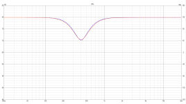
Nonetheless, I'm curious what if I don't obtain the deep null but instead two response curves with nearly identical patterns to each other, regardless of whether the polarity of one driver is reversed or not. As seen in the first image, SPL, the blue and orange lines are frequency plots of flipped and unflipped one driver's polarity, which are nearly completely following each other. Their phase plots, however, do not.
The question is whether these two cases produce the same sound that the listener will hear. If not, which is more accurate and should be selected?
Note: The graphs are created using VituixCAD software. Corner frequencies of the low- and high-pass active typed filters are 300 and 540Hz, respectively, with fourth-order Linkwitz-Riley characteristics.
Attachments
Last edited:

You can see on the graphs you posted.I'm curious what happens if I don't obtain the deep null but instead two response curves with nearly identical patterns to each other, regardless of whether the polarity of one driver is reversed or not.
Yes, that’s neither a null nor Butterworth filters. They’re Linkwith-Riley filters as stated in the last paragraph.That's not really a null. It looks like two Butterworth filters with a large gap between them.
You have several parameters that are changing. Each has it's own effect. Asking which is better is about breaking down these effects.
So, it changes..
1. Response,
2. Power,
3. Lobing,
4. Phase/group delay
One of these in particular?
So, it changes..
1. Response,
2. Power,
3. Lobing,
4. Phase/group delay
One of these in particular?
Two drivers don’t have to be in phase for a quite linear phase behavior of the acoustic response. It even gets better, for both a good on axis and power response, you’ll likely won’t end up with two drivers in phase. So the “null” test is moot, actually.
Please everyoneThe question is whether these two cases produce the same sound that the listener will hear. If not, which is more accurate and should be selected?
Attached is my active LR4 acoustic on-axis response with the connection to the mid driver reversed and not reversed. There's a tweeter phase shifter built into my active crossover to achieve proper acoustic alignment despite the physical offset of driver centres. Could have been done with digital delay to the tweeter channel in a fully digital system, but I don't have that. Had there been say near-quadrature (90 degree) misalignment, both curves would dip smoothly (no sharp cancellation) by around 3 or 4dB only. Anything other the the red trace would be unacceptable to me for my set-up. Minor perturbations can be addressed up-front with DSP once the basic alignment is set up properly.
Attachments

You speak as though we haven't just given you the key to this problem..?Please everyone
Some of us don't like to guess on things we know are subjective, but let's take a journey out into the woods for a moment.. They probably will sound close to the same, provided you listen in an anechoic chamber and the slopes aren't too steep.
Just re-read the OP which says "Corner frequencies of the low- and high-pass active typed filters are 300 and 540Hz, respectively, with fourth-order Linkwitz-Riley characteristics."
Why would you do that? LR4 HP and LP corners must be at the same point. Otherwise it isn't LR4. Can't assist any further here. The question is too silly.
Why would you do that? LR4 HP and LP corners must be at the same point. Otherwise it isn't LR4. Can't assist any further here. The question is too silly.
So these are simulations? No doubt real measurements will be more accurate on what is happening.Note: The graphs are created using VituixCAD software.
It’s just an experiment.Just re-read the OP which says "Corner frequencies of the low- and high-pass active typed filters are 300 and 540Hz, respectively, with fourth-order Linkwitz-Riley characteristics."
Why would you do that? LR4 HP and LP corners must be at the same point. Otherwise it isn't LR4. Can't assist any further here. The question is too silly.
It’s ok if you can’t help any further. Thank you anyway
I guess for demonstration purposes, regular first order would do. The phase will be the same as you've shown and the response will be flat with either polarity.
It seems to me that you are probably still 'learning your software' but also have a misunderstanding or two.Just re-read the OP which says "Corner frequencies of the low- and high-pass active typed filters are 300 and 540Hz, respectively, with fourth-order Linkwitz-Riley characteristics."
Why would you do that? LR4 HP and LP corners must be at the same point. Otherwise it isn't LR4. Can't assist any further here. The question is too silly.
By having two filters being 240Hz apart, were you trying to devise a test for driver phase orientation or what ?
Although I can't see frequency range of your first picture, the slopes don't even look fourth order. (?)
Re. null & notch, a properly built first or second order XO will present a 'suck-out' when the drivers are out of phase.
Higher order filters will change the Q of overlap, thereby reducing the audible effect of driver phase orientation >
however, such can easily produce a notch depending on driver phase orientation.
( electrical and acoustic phase both exist )
IMHO, basically these two transfer functions create a degenerated Butterworth XO (actually, XO target functions) with a constant 90 degree phase offset. Degenerated in that it has that dip in the SPL magnitude vs. frequency plot. If you fill the dip with global EQ you'll end up with a proper (flat SPL response) Butterworth XO, still having the 90 degree offset.
Like with all 90 degree phase offset type XOs, the Butterworth XOs, SPL summed magnitude must stay the same when one way is inverted but phase will change. The correct phase of the sum is the one which is "faster", that is, has the lowest value of total phase rotation, the shortest step response. The other polarity will introduce a first-order allpass filter which additionally "delays the bass" -- and that is (slightly) audible.
For Butterworth XOs, the "inverted polarity null test" actually becomes a phase match test, that is, how good it approaches the constant 90 degree offset target, besides the correct magnitudes.
Well, I believe I should describe my experiment to everyone so that everyone is clear. I carried out the experiment to investigate the frequency response change. I began by adjusting the high pass frequency to 540Hz and the low pass frequency to 270Hz using the slope of 4th-order Linkwitz-Riley characteristics. Then, flip the polarity of one driver to see how the frequency response curves aligned. The low pass frequency was then increased while the hi pass frequency remained fixed—at 540Hz: 270 > 280 > 290 > 300 > 310 > 320Hz. What's fascinating is what happens when the low pass is set to 300Hz. On the curves, there was essentially no difference between reversed and non-reversed polarity situations. As a result, I came here to ask my questions.
It became a question since the frequency replies are virtually perfectly synchronized. The phase responses, however, do not.
The question is whether these two cases produce the same sound that the listener will hear. If not, which is more accurate and should be selected?
It became a question since the frequency replies are virtually perfectly synchronized. The phase responses, however, do not.
Last edited:
- Home
- Loudspeakers
- Multi-Way
- Which one is more accurate if the deep-null check is not valid?