Lowering rectifier voltage in tube amplifier

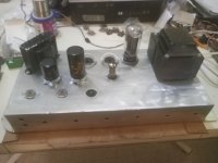
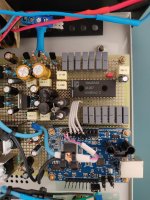
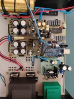
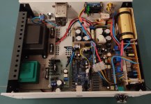
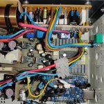
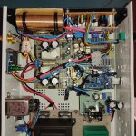
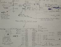
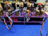
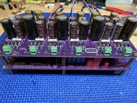
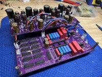
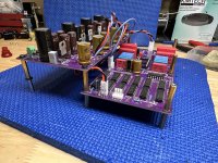
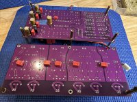
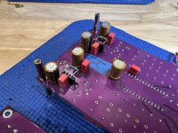
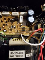
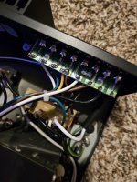
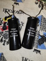
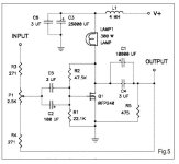
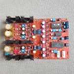
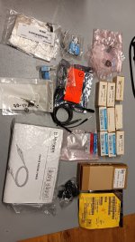
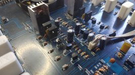
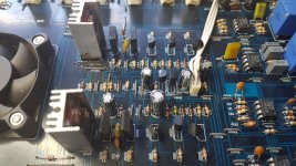
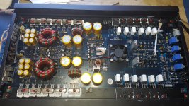
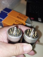
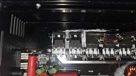
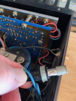
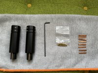
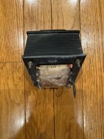
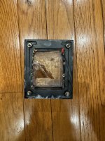
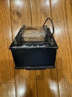
I've been all over the Internet looking for a good answer to lowering the voltage down after The rectifier tube. I have a 5U4GB rectifier tube in A 6l6 GC PP amplifier. 525 on The Plates , 400 on The screen and - 26 Bias. This is with the Rectifier tube in and the output tubes out. Also I have a 100 ohm 1 watt resistor going to the second can getting extremely hot. I'm guessing that it is the one lowering the pre Amp section down to 400 At the second can. My Filter Cans are 500 volts 50/50 and 32/32. A little bit more filtering than the amplifier had in it originally. 40 and 20 were in it originally. I'm going to The 50/50 first. Line is At 123 AC. My plan was to put a 10 watt 100 ohm cement resistor after the rectifier tube and before the first filter can. Also to put one in the place of the one getting hot for the pre Amp power on the second Filter can if the first resistor doesn't cool it down to a reasonable amount of heat. I would think that It should be able to stay cool especially with the two 6l6 tubes out. I also put a 1 ohm resistor on the cathodes so I can read the ma of the tubes..I wasn't sure where to put the two 5k Bias pots At. Or if I really need them or not. I have switched over the chassis with this thing and I don't have any type of wiring diagram for it. It came out of a 1960 Whirlizer Organ and without knowing what organ it came out of the wiring diagram is impossible to find. The amplifier number is pretty much useless in finding it. Whirlizer 501273 is the amplifier number for what it's worth. I've been reading about using chokes also but I don't know if I should go that way without knowing anything about the specifications. Seems much easier to use resistors first to get it under control. It seems like 100 ohms in 10 watts resistance is pretty standard for lowering down the voltage. I've Used 120 ohms Cement resistors At 5 watts before in small tube line amplifiers to get the running voltage down after the rectifier tubes. It seems to work pretty good in them. But A small line amp and this 6l6 GC seem like they are world's apart. I'm also A little concerned with the low amount of bias voltage -26 being supplied. Any help appreciated. It's a project Amplifier.

Attachments

  • IMG_20240527_143020.jpg
    IMG_20240527_143020.jpg
    256.9 KB · Views: 51

Hello All

Dipping my toes into the deep end of audio and the google machine keeps bringing me here, so I figured I would make an account. I am not sure how much I can contribute to the vast amounts of knowledge and experience here, but perhaps my questions can help light the way for someone else in the future. "Standing on the shoulders of giants" seems a rather apt description.

underhung woofers

Just one question, what would be the advantages of an underhungs vs overhungs woofer, which reproduces a wide range of frequencies (50 to 2,000 hz)?

From what I know, underhung woofers would have better magnetic flux than overhung woofers, thus reducing distortions, but depending on the cost they may have lower xmax (excursion), in addition to the fact that when the excursion limit is exceeded the distortion level is greater than the overhungs.

An example of a subwoofer with high xmax (excursion).

Attachments

  • Sundown Audio Nightshade V6 (15 inch).jpg
    Sundown Audio Nightshade V6 (15 inch).jpg
    142.2 KB · Views: 182

2SD1782K _ is there a not smd equivalent ?

Hi ! i have a kind question about possible alternatives to the 2sd1782k
I cannot use it because it is smd Are there equivalent bjts not smd ? (unfortunately LTspice i am using does not mention the type of package That would be very helpful for a beginner like me)
I have to find something easier to work with even if i lover the look of the smd circuits immensely
thank you very much
have a nice day
gino

Audio Analogue Puccini Settanta schematic or service manual needed

I am looking for the diagram for analog audio puccini stettanta.
I have one on the table with an underlying problem and I need the diagram before dismounting it completely to access the underside of the pcb.
I sent an email to Audio Analogue but no answer and unfortunately, the diagram of Puccini settanta is very different from other puccini.

Passive 3-Way "Bookshelf Plus" Speakers

I wanted to start this thread to share my progress on a custom 3-way speaker design that I have been working on. This design heavily draws inspiration from hifijim's LLCAM speakers due to the great technical details and well explained design process. Other aspects come from people such as Augerpro for the waveguide desing and Troels Gravvsen for the general cabinet shapes and crossover design.

The goal of this project is to be a moderate cost 3-way passive speaker design with good technical details and act as a solid home stereo setup in my living room. I have built and designed other speakers in the past with a much less technical design process, so I wanted these to leverage as much of the community knowledge that I could understand. I would still say that much of this project is "half-assed", where some of the technical aspects were added in spirit as opposed to objective testing.

For driver selection, I went through many iterations myself, including much of FaitalPros, SB, and Daytons driver choices. After much thought, I basically settled on the same driver selection as hifijim did in his LLCAM speakers that I drew inspiration from. As this is a passive design, I went for components that had a relatively flat response and that I thought would be somewhat straightforward to design an XO for, but this is yet to be seen in practice. The parts include:

Woofer - Dayton RS270-4, ~300-400 Hz XO
Mid - SB15NBAC30-4
Tweeter - SB26ADC in Augerpro 4" waveguide, ~2200-2500 Hz XO

The enclosure design includes a ~30L vented enclosure tuned to 32Hz for the woofer and a 4L sealed enclosure for the mid. I have done some work on designing a custom port that will be 3D printed (due to the space constraints of the internal volume) which will have a roughly 3" diameter and 13" length. The port design is not yet finalized, but I have been looking at stv's thread on port design and may see if I can design something using the findings that he has been making over there.

1716932706205.png

The front baffle was orignally designed using a similar method in Vituix that hifijim mentioned, using varying baffle chamfers for each driver to "simulate" the chamfered corner. For this, I initially designed the baffle with full downwards cuts, similar to what Troels uses in some of his speaker designs, for aesthetics. With simulated baffle diffraction, traced speaker SPLs from spec sheets, and a very rough XO design, the results seemed promising enough for me to continue. During the process of building the cabinet, I decided to not add the chamfers due to a waveguide already being used and the mitered corners with custom red elm veneer looking too good for me to cut it off. I am hoping this will not affect performance greatly, simulations did show it was marginally worse but not awful.

1716932718171.png
1716932787771.png

The inside of the cabinet is supported by two braces, one which is integrated with the mid chamber and the other which supports the woofer. The front baffle thickness is nominally 3/4" on the mid and tweeter, but a second MDF baffle piece was added to the woofer making it a 1.5" baffle thickness. Most free faces of the cabinet were covered in 80mil butyl/bitumen sound deadening pads and then in ~1/2" denim/cotton mats. I plan to later add natural wool stuffing to the enclosures by ear. The rough outside dimensions of the boxes are 14.5" width, 25.5" height, and 11" depth, making them "bookshelf plus" in my mind. Overall, the building process went well (other than not cutting the chamfered edges), and the cabinets look amazing with a wipe on poly coating on the red elm veneer.

1716932898501.jpeg
1716932999528.jpeg


I don't plan on making any significant progress in the coming weeks/months as I will be moving cross-country shortly to begin a new job. When I make sufficient progress on this project, I will make another longer update post. I'll try and be somewhat active if anyone has suggestions/questions about this project.

Cheers - O

Attachments

  • 1716932940510.jpeg
    1716932940510.jpeg
    658.8 KB · Views: 76

For Sale PeeCeeBee V4H Lateral Mosfet amplifier (Best Offer)

I recently disassembled my V4H amplifier to use the chassis for another project. Rather than putting these perfectly working amp modules on the shelf to collect dust I figured to put them up for a Best Offer sale. Built with top quality parts the amp boards are premounted to a 3/8" thick aluminum plate. Drill four M4 holes in the heatsink and mount the complete module. They were powered with a Cresnet (Micro-Audio) SMPS +/-53V. What the heck, make an offer for the SMPS if also interested.
Cheers,
Vunce

Attachments

  • IMG_2171.jpeg
    IMG_2171.jpeg
    631.4 KB · Views: 146
  • IMG_2170.jpeg
    IMG_2170.jpeg
    591.8 KB · Views: 151

TDA1541A NOS in simultaneous mode, my personal journey

Hello everybody
I'm not an expert but learned a lot reading this site. Thanks for that. This personal journey started some time ago, when I decided to build a DAC based on the TDA1541A
The first step was buying some old and malfunctioning CD player for a few bucks only to desolder and get the chip (photo attached).
Second step was to buy a JLSounds i2s over USB pcb v. 3, with the recommended mute card, then the rest of the components and a cheap enclosure.

Started easy but then I decided not to use a third party pcb but to solder point to point. Then added something new, a relay based volume control, just not to need any pre (passive or whatsoever) and to have all in only single box. Afterwards I decided to build the analog part without opamps, but with the simple FET-MOSFET as designed by Dietmar W. Gerhold (the "infamous" fetishizator V2.2) you can find on the web, and to use a simple but special non inductive resistor polarized at 0 Volts as the I/V converter. This last aspect also is not of mine but taken from this site threads. Thanks again for a lot of valuable information.
The only modifications to the fetishizator V.2.2 from Dietmar W. Gerhold were:
  • FET BF245A source resistor reduced to 330R to get the proper drain voltage to let it swing, something between 11 and 12 Volts (my FET happens to have a very particular Vgs)
  • V+ set at 18 V
  • 10 uF OBBLIGATO GOLD output capacitor and afterwards a 32R in series to have something to tame the "click" of the mute board when it shorts the AC output. With this it's 100% silent.
  • added after the mute board (not because I'm sure it will filter something, but because it's better to have something than nothing) a very little air wound inductance hand made and measured to be 0.25 uH. This can make laugh but please stay put... 😉
Two transformers (2x15V 30 VA + 9V 6VA only for the USB part consuming 400mA) and six regulators LM3x7 based with CRC each (+5V for the TDA and the non USB part of the JLSounds card plus the mute board; 2x +18V for the fet output, -15V for the TDA, -5V for the TDA and other +5V for the USB part of he JLSounds card).

Reaching +/- 5V from a transformer with secondary rated +/-15V constrained me to use CRC with big resistors not to overload the LM3x7 chips, even with heatsink. This was a decision made and that's the reason I'm protecting some caps with a little cardboard piece (a hot 4 watts resistor nearby don't pleases me, even with 105 degrees caps).

The results:
After changing the fet source resistor to 330R during "commissioning" things started going very well. The sound is very very clear. This analog output can drive even headphones directly. My impressions are absolutely subjective. I'm driving an Aleph 30 clone with this and the sound is spectacular, specially in the highs, very clear and transparent. Hopefully this amp is not suffering from the ultrasonic load.
The only thing that can be annoying is the click of the relay based volume control, but as it only clicks when adjusting the output volume (the relay sound) this is something very bearable.
For the rest the sound is really amazing.

Some pictures of the journey, including one of my sketch sheets (not very good writing or designing things, excuse me for that). In the pictures from above the short description is: main boards are soldered point to point using the same components legs were possible. Only one ground wire without loops of any kind. At left the transformers. At right the two obbligato capacitors and the relay volume board. At the end, beside the output RCA connectors is the mute board (and the coils). The JLSounds card is inserted as a kind of daughterboard on top of the main pcb. The socket for the TDA1541A was presented but finally not used, and the cap legs are soldered directly to the TDA legs without any bridge.
Many thanks

Attachments

  • 00 TDA1541A to desolder.jpg
    00 TDA1541A to desolder.jpg
    366 KB · Views: 287
  • 01 TDA1541A First Presentation but not used.jpeg
    01 TDA1541A First Presentation but not used.jpeg
    404.5 KB · Views: 180
  • 02 TDA1541A First Steps.jpeg
    02 TDA1541A First Steps.jpeg
    362.3 KB · Views: 184
  • 03 TDA1541A First Tests.jpg
    03 TDA1541A First Tests.jpg
    527.3 KB · Views: 187
  • 04TDA1541A First Tests 2.jpg
    04TDA1541A First Tests 2.jpg
    496.4 KB · Views: 184
  • 05 TDA1541A back.jpg
    05 TDA1541A back.jpg
    181.5 KB · Views: 177
  • 06 TDA1541A overall finished.jpg
    06 TDA1541A overall finished.jpg
    457.4 KB · Views: 167
  • 07 TDA1541A finished 1.jpg
    07 TDA1541A finished 1.jpg
    792 KB · Views: 190
  • 08 TDA1541A finished 2.jpg
    08 TDA1541A finished 2.jpg
    797.8 KB · Views: 192
  • 09 TDA1541A finished 3.jpg
    09 TDA1541A finished 3.jpg
    621.1 KB · Views: 264
  • 10 TDA1541A sketch Analog Part.jpg
    10 TDA1541A sketch Analog Part.jpg
    319.5 KB · Views: 271

Noisy Bottlehead Crack

Hello. This is my first post here.
I have seen a number of helpful threads and thought I would give this a try to fix the issue I am having with my Bottlehead Crack tube amp.
Since a couple of months now I have been trying to fix a horrible noise that my amp is having, making it unusable.
The amp had worked fine for around 3 months, but then one night I heard a loud crackling noise in the right driver. Since then every once in a while I could hear a noise like crackling, always in the right channel, but I could interact with it and sometimes make it stop by moving the power tube a bit.
Fast forward a couple of weeks, the noise is always present and doesn't leave no matter what I do (messing with the tubes doesn't do anything anymore), meaning that I cannot use my beloved amplifier anymore.

I have tested and tried fixing this for a long time and this is a description of what I have found.

-The noise sounds like crackling and it comes and goes randomly. The intensity also changes randomly.
-The noise is not tube dependent: no matter how many tubes I try on the problem doesn't change.
-Wiggling either tube does not have an audible effect, and the socket and tube pins look rather clean.
-The crackling noise appears soon after the amp is on, I would say in about 10 second's time. When I turn the amp off it disappears after 3 or 4 seconds.
-The noise is exclusively in the right channel.
-The noise does not depend on whether I have the RCA's connected or not, and it does not change depending on which wall outlet I plug it in (not even going to a different house made a difference, so the noise is not coming from a wireless connection either).
-The noise doesn't change depending on volume. It's always there at the same volume.
-The chopstick test did not reveal any weak connection in the solder joints. Even lightly pulling/pushing on wires I couldn't notice any audible reaction. The possibility of me not noticing a bad joint is of course possible, but I have tested for so many hours that I would find it hard to believe.
-Applying pressure on the chassis in several different positions did not reveal any audible changes.

Here is a recording of the noise (please ignore the clock noises and the faint background static).
Of course I'm available to send any close up picture that might be needed.

I have gone back and resoldered each solder joint several times, making sure that they look as good as I could make them with the right amount of solder and not having them be cold. I used the reccommended 60/40 solder.

I have a rather long thread still open on the Bottlehead forum with some pictures, but even though the kind people over there tried suggesting some things, nothing has worked.
I have spent so many hours trying to fix this amp and I really miss listening to it, so if anyone has any idea on things to try I would greatly appreciate the advice. Please help me out.

Using 4 Ohm OPT taps with 8 Ohm speakers to double the primary impedance

I'm researching a Tubelab SSE build using a pair of NOS 6P3S-Es, which I've found locally at a good price. The design of the SSE calls for a 5K OPT and I had been thinking of going with the Edcor GXSE10-8-5K, but given that I live in the EU, I though it might be preferable to go with a Toroidy toroidal OPT. Now their model for EL34, 6L6, 6P3S, etc. tubes is the TTG-EL34SE [1] which has a primary impedance of 3.2K. (My guess is, it's meant to be used at lower B+ voltage and higher currents, since it's also gapped for 100mA nominal anode current.)

This would cost about as much as the Edcor and it seems to be better, at least in terms of specification (seemingly larger core, going by the weight and 51H primary inductance vs 6H for the Edcor, hence more extended frequency BW, etc.), so I've been thinking I might use that and simply connect my 8 Ohm speakers to the 4 Ohm taps, to get a 6.4K primary impedance which ought to work fine for my application. As far as I can tell (and that's not very far) this should work ok, since most of the specifications (perhaps with the exception of leakage inductance) seem to primarily determined by the core and primary windings, which won't change.

Now, I can also get a custom version of the TTG-EL34SE wound for 5K primary impedance, albeit at about 50% higher price. Would that be worth it? What could be the difference of the custom version, in terms of design and operation, with respect to using the 4 Ohm taps on the default version?

Calling CD/SACD Laser experts

Hello,

Attempting to fix an Onkyo DV-SP1000 that no longer reads CDs. Could read DVDs/SACDs. I ordered a new laser claiming to be Genuine sony, but finding it doesn't work. (yep, I desoldered the 2 blobs and was anal about static). The laser unit in question is a Sony KHM-280AAA

Unforutnately, since the new laser didn't work, I played with it's pots before taking baseline measurements, and used the old pickup to practice turning the tiny pots. Of course, they are now, both not working!

It's possible I may have connected the FPC cable incorrectly, but want to get back to the original settings to retrace my steps and correct everything along the way. Hopefully I haven't blown the diodes on the new one, but have ordered a replacement anyway. (this time from an US supplier claiming it's genuine Sony)

As the new laser is a few days away from delivery, I was hoping to try and get the unit going and perhaps salvage the purchased unit, if it's not defective and just needed a slight adjustment.

Few questions.

1. Anyone know a good starting point to adjust the pots to before installing? 900 ohms each? Going to try again, hoping I made a silly mistake, but want to get back to a good starting point, and unfortunately didn't do andy before adjustments.

2. Ribbon cable orientation. Assuming pins up install on both the Laser head and the PC board? (I can test this with a multimeter, but wanted to know if there's a standard way, as I've not worked with FPCs much)

Any and all responses appreciated!

Simulation in DipTrace 5.0

I have created a schematic, see the attached screenshot. Now I am trying to simulate how it works in a digital SPICE simulator (built-in DipTrace 5.0 beta).

14.png


In general, it works almost reasonably. But there are strange signal distortions on some outputs of U3 on each falling edge of the clock coming to the input of decade counter U5. I have shown the problem with red marks.

15.png


What I am doing wrong? Is it a simulator issue or the schematic is incorrect?

Help please with my poorly Stasis 2

Hi Gents.
Recently bought this Stasis 2 as faulty ( the only way I could ever afford one )
Symptoms were : slowly over time was brought up to 240v using a variac , then used for a week until smoke was seen and then the left channel went down.
I’m no engineer but I can replace parts so I’m hoping someone can steer me in the right direction.
Any idea which component(s) have failed and caused the burn ? ( see photo also )

Any assistance would be greatly appreciated.


IMG_5108.jpeg
IMG_5114.jpeg
IMG_5114.jpeg

For Sale TDA1541A NOS DAC board and PSU board

TDA1541A NOS DAC board info:
https://www.diyaudio.com/community/...st-tht-i2s-input-nos-r-2r.354078/post-7159210

Power Supply Board info:
https://www.diyaudio.com/community/...st-tht-i2s-input-nos-r-2r.354078/post-7159234

Add your own opamps, TDA1541A DAC chip and clip on heatsinks to regulator IC's (I removed the HS for another project) and you're ready to connect to I2S source and power transformers. True to my style, the components around the opamp sockets are mounted underneath out of the way to facilitate easy I/V experimentation.
The length of the PSU output wiring harnesses enables stacking the boards (psu top tier) or stepped next to each other.
SOLD! shipped in N.America, PayPal F&F

Attachments

  • IMG_2107.jpeg
    IMG_2107.jpeg
    726.5 KB · Views: 156
  • IMG_2110.jpeg
    IMG_2110.jpeg
    671.2 KB · Views: 153
  • IMG_2111.jpeg
    IMG_2111.jpeg
    698.3 KB · Views: 136
  • IMG_2112.jpeg
    IMG_2112.jpeg
    730.9 KB · Views: 135
  • IMG_2113.jpeg
    IMG_2113.jpeg
    663.1 KB · Views: 132
  • IMG_2114.jpeg
    IMG_2114.jpeg
    580.7 KB · Views: 117
  • IMG_2115.jpeg
    IMG_2115.jpeg
    520.4 KB · Views: 153

Mark Levinson 383 "Amp Fault"

Hello, I have a Mark Levinson 383 amp here, which unfortunately brings the error message "Amp Fault".
I've already replaced all the capacitors because they weren't good before, and also the 10nF bypass capacitors because they were already burned out.

Without a circuit diagram, troubleshooting becomes difficult. Does anyone here have a wiring diagram?

So that I can at least start looking. Nothing burned as far as I could tell.

best regards Markus

Impedance Issues..... Again..... Need help on this 3 way

Hey all,

I am designing my first "proper" 3 way where I don't let the mid just fall off naturally on the low end. I notice with this band pass filter that my impendence is sent to the moon. I am very new to band pass filters. Is there anything super obvious I am missing or is this all just a very poor design? I have thick skin so have at it. I am not super proud of this or anything and am just a poor hobbyist amateur trying to make some HIFI for my own enjoyment.

The drivers:

Planar tweeter: https://www.parts-express.com/HiVi-RT1.3WE-Isodynamic-Tweeter-297-421?quantity=1

Mid: https://www.madisoundspeakerstore.com/approx-4-midrange/sb-acoustics-sb12nrxf25-4-4-midrange-4-ohm/

Sub: https://www.parts-express.com/Peerless-830667-8-Paper-Cone-SLS-Subwoofer-264-1102?quantity=1

What I have done in the past is to run the mid and woofer in series to deal with impendence. I can't really do that with the band pass filter. Or can I.....? Please let me know. I am entirely open to suggestions.

Attachments

McIntosh & Rubycon

I have a couple of vintage McIntosh preamps, a beautiful C46 (a real gem and favorite of mine) along with an interesting CR12 I picked up from a fellow who claimed it fell victim of a power surge. I've recapped both; the C46 I was surprised how many of the caps have drifted, some significantly - now, I know this wonderful preamp is gaining in years, but I wasn't expecting the kind of electrolytic drift I was measuring across the old caps. Needless to say, great improvement, and I redid it using Vishay audio electrolytics, which I find absolutely excellent. It is a big improvement now having it operating as it should.

The CR12 on the other hand, unique piece. When I received it, it barely turned on, caps in the power section were bulging and hot to the touch! I thought voltage regulators, but just replaced everything and it brought it back to life. Added new lamps (old were blown) and score. Now, recently I took it a bit further and removed the output board, basically 4 output stages on one large board and shocked to see the state of the caps on that. Some of them were measuring in at pF range - totally shot, baffled at how the thing even produced a listenable sound.. I just completed the entire board, 60+ caps, many 10uF, and what an experience - I have it feeding a couple of stacks of equipment all running in my workshop. Despite being basic from an audio standpoint, it produces a great sound now.

Now, the question/topic. All caps Rubycon. I always thought of Rubycon as in a similar range as Nichicon, but are these caps suspect? Did McIntosh take a bit of a wrong turn with Rubycon? Working on Mc gear is just a pleasure.. Maybe akin to working on a mercedes.

On the C46, I also did some audiophool stuff like teflon caps on the phono stage, added solid core silver wire as power jumpers - but won't get into that too far to avoid the debate. I was extremely fortunate to be able to have received a replacement encoder from Mc for that unit since the old one was damaged - suspect from the previous owner pulling off the knobs, bending the optical disk inside.

Rubycon, are they a con?

[Noob Question]SoTA Dac implementations in respective categories

Which dac implementations are considered State-of-the-art for ESS, AKM and R2R categories respectively by the DIY community either in DIY for sold commercially (I say community because different communities will have different biases). I understand there won't be a single conclusive answer but some names would pop up more often IME.
The motivation behind the questions is as a noob which Dacs should I focus on first and then branch out based on my sonic preferences.

So far I have built a fully loaded IanCanada dual mono dac stack and will be building a DDDac v3 in a couple of months.

Need help with Bogen C100 Classic series Amplifier PA system

Hello, I am new to electrical engineering, but I am competent enough to understand a lot of the basic things. I am trying to fix a Bogen C100 that I acquired, and have attached the schematic provided by the manufacturer. When I got it 2 of the resistors had catastrophic failures and at first I didn't know why, and don't fully understand still. They are R70 and R77 both 22ohms. I replaced those with the same type and value, and when I turned in on, the BJT, G17, burned up. I believe R74 also was overstressed because part of it charred, but it didn't fail completely. It's value is also unlabeled on the schematic and I pointed it out. I got another BJT, a 2SD718 NPN BJT. I replaced that, but I didn't replace R74. I connected everything back, but a connector to another part of the circuit, wasn't plugged in. It was a 3 pin connect that I believe connected to the front potentiometer volume knows and it's board. There is only one actual plug connector, everything else is tab connectors on the main board. From what I remember that should mean that any other boards connect through that boards connection as well. When I turned it on that time, i saw sparks on what looked like the main board near the ac main side, but cant be 100% certain. I checked everything and nothing seem bad, burnt, or otherwise hurt. I noticed connectors between GND and COM as well as between LINK and 4ohm. I was wondering is something was shorted, so I checked for continuity on those connected terminals and all the others to include the 25V, 16ohm, 70V, and right end GRD. They all had continuity with each other, but I don't know if that is supposed to be like that or not. I ended up takeing off the connectors between them and turn it on again, I believe I plugged the 3 pin connector back in. Well the new BJT catastrophically failed and burned a hole on the right side, which may be the emmiter. The resistor that was unlabeled R74 also seemed worse. I measured the resistance of it before and it measured 219ohms in the circuit, but now value starts below that and climbs. I can't read the value because the middle 2 rings are charred off and or lost their color. I don't have a full picture of the internal components right now but but will be able to attach one later. I am attaching everything else I have and an image I found showing those back connectors.

So my questions are as follows;
1. What is the value of R74 supposed to be?
2. What could I have caused to make components fail?
3. Why is the device and components not working correctly.
4. Can I safely test components to make sure they are good and if so how? (If desoldering is needed that's is fine)

Attachments

Durable coatings for Stax SR-007 ESL diaphragms

Dear all,

I'm rather new in this community so I cannot ask the standing experts directly yet. Here's my conundrum: I'm currently making a new pair of diaphragms for my Stax SR-007 Mk1 electrostatic headphone as one of the stock diaphragms tore up and Stax refused to receive the unit for a repair quote (long story). I've already geared up with the needed materials and tools, including new custom-made pcb stators, 1.4 um Mylar film (the stock SR-007 diaphragm is 1.35 um thick) and a Mylar stretching device to tune the diaphragms in matched quads (good to have spares), thanks largely to the generous advice from Head Case user chinsettawong who has been helping me remotely with this task.

My current choice for the coating material is a silicone-based graphene spray used for car detailing, but my previous experience with using it for recoating did not yield great results at all regarding durability (channel imbalance returned after a couple of days at the longest), even with some buffing. I was considering trying to "enhance" the spray with reduced graphene oxide (RGO) powder, but I'm skeptical this will improve durability of the coating at all. That's one of the reasons why I haven't started making the new diaphragms yet (other reason is lack of time, but that's another matter...) - I'm currently looking for more promising, longer-lasting alternatives for the coating material. I don't want to keep reopening my SR-007 every couple of months to recoat the diaphragms.

My assessment of some of the alternatives around:
  • Antistatic sprays such as Licron Crystal and Staticide are unobtanium for me here in Brazil, these are usually not shipped abroad for being hazardous goods. Thus, not really an option. Besides, mileage seems to vary regarding their durability as a coating material.
  • Antimonium-doped tin oxide (ATO) seems promising. diyAudio user neil5m used the ATO antistatic coating solution RB-048 by Shanghai Huzheng to restore his pair of MartinLogan Clarity ESL's, but he also reported on this coating being rather humidity-sensitive. Head Case user Kung also used an ATO alcohol solution to "repair" (more like rebuild...) a pair of Hifiman Shangri-La Jr. e-stat diaphragms. Despite Shanghai Huzheng claiming a duration of 5 to 8 years for the coating, I'm still curious about actual long-term longevity in my scenario.
  • Finally, there is the HTEC coating solution by diyAudio user Martin-Jan Dijkstra. Have just learned about it, so not much to say on my behalf. I'm currently unable to PM him directly to know more due to my being a diyAudio newcomer. Edit: Mr. Dijkstra has just answered to a query of mine and informed that HTEC has been discontinued, so this is no longer an option either.
  • The ideal solution would be to do as Audeze did with the CRBN e-stat and have an appropriate conducting material embedded into an appropriately thin polymer matrix (they use carbon nanotubes, hence the name), no longevity problems at all with that. However, only Audeze seems to be able to get something like a 1.4 um thick, carbon nanotube-infused Mylar film with an appropriate surface resistivity (my SR-007 measurements point to 4 x 10^8 Ohms/sq. as a reference point).
Any ideas? Thanks in advance.

FR of Frugel-Horn Lite???

Hi, I am new to speaker building and decided to make a pair of Frugel-Horn Lite speakers using Fountek FE85 drivers. I got one finished with the specified damping (felt and fluff) installed. I assembled the other one, and out of curiosity did not install any damping material. Tested both (see below - lower curve is the non-damped speaker). The damped one is louder but both have an (what I think) is an alarming drop at 5kHz. I don't know what to make of the results. I would very much appreciate any advice/ideas for a new speaker builder.

Testing of TL speakers.jpg

Strange clipping problem with my Aleph J build

A few years ago I built a bog standard Aleph J amplifier using the DIY Audio boards and chassis. It drove my 88db efficient KEF R500 speakers without any issue and was the mainstay of my system for quite a while. It sounded great at mid-to-not quite loud levels.

I got back into tubes and kept the Aleph J as a second amplifier. Fast forward two-something years: I pulled the Aleph out of the closet and plugged it back in. Same speakers, same tube preamplifier... but now the Aleph seems to clip very, very easily. Sounding more like a 1W amplifier than well, its rated power. I checked the main supply voltages/offset and can't find anything obvious. What to check next?

Clipping happens with both channels which makes me think power supply! My tube amp is no power house - rated at 35WPC (old school) with a breeze blowing behind it. It drives the KEFs without any issue. Positively flummoxed by the Aleph change in sound.

SemiSouth SJEP120R100A Circuit Question

Hi Folks,
I was just gifted a pair of the SemiSouth JFETs. I am looking to build something with them, and my #1 choice would be F2J. There was PCB for the F2J for sale on Diyaudio Market place a few years ago, and just requested if they had any more. My fall back plan would be adopting the Zenlite circuit to use the SemiSouth SiC Jfet. I am comfortable building Vacuum tube circuit as a hobby, but I never built a Solid State amp, so this is new territory for me. I figure the IRFP240 and the SiC Jfet are both Enhancement-mode devices, the only thing I need to figure out is setting the positive voltage bias at the gate, finding the correct amount/type of light bulbs to set the current, and find the correct V+. Am I looking at this too simply? Is this a good Idea ? I'm am hoping to find the F2J PCB. I've included the circuit from the zenlite diy article.

Attachments

  • zenlite.jpg
    zenlite.jpg
    41.5 KB · Views: 397

ICEpower 125ASX2 in BTL mode using DSP

Hi I have an ICEpower 125ASX2 and want to set it up in BLT mode. I have seen in the documentation that the signal to channel 1 needs to be inverted. I am powering it using a ADAU1701 AMP2 dsp board that outputs RCA and works fine under normal operation.

Can I set the DSP to make one of the RCA Inputs 180deg out of phase and use for ch1 input while in BLT mode? (I would also mix the L/R to mono in the DSP
Thanks for your help!
1716301389065.png

UDNeSS, or You don't need Semisouth's

There is quite a bit of excitement recently about the unobtanium Semisouth SJEP120R100 power JFETs
that Nelson Pass uses in his First Watt products, such as the mysterious J2.
So much so, that the prices on ebay went up by 67% in one weekend.

If only as an attempt to provide an alternative, I promised to post something similar but without any unobtaniums.
https://www.diyaudio.com/forums/pass-labs/342850-sjep120r100-ebay-real.html#post5922830
(Post #22)

So here you are. I am quite surprised myself that it came out so well, even if only in simulation.


Happy reading,
Patrick

.

Attachments

Strange noise from Prism Sound Lyra 2

I am trying to identify the noise problem I am having with the Left channel on the Lyra 2 interface.
I will post a video clip so you can hear what I am talking about. Its not only this noise, this channel has
10dB less gain than the Right channel.
I contacted the technical support of prism sound but they suggested to reflash the fireware but this didnt solve the problem.
I hope you can help me.

Thanks.

Attachments

  • noiselyra2-1.mp4
    1.3 MB

Dual membrane planar magnetic (both active driven)

I had this idea for a looooong time, no steel and higher X max, and hoping for more linear movement, by the looks of it you can increase xmax allot while still have it more linear then normal single ended (2e order droped allot). in this case i went from my regular 3mm xmax to 6mm 🙂

Login to view embedded media and some music see if we can hit the magnets... no luckl so far, res to high and xmax as well

Login to view embedded media

Muses 72323 Buffer Board

Dear All,

I produced few Muses72323 Input selector Buffer and volume control boards for my pre-ampifier. The board has four inputs, a DCB1 buffer and the Muses72323 volume control. One board has two channels. Low noise regulators on board.

I have an Arduino code to control the Chip.

Note: The boards have two little mistakes that can be easily fix when assembling them.

THIS IS NOT A BEGINNER PROJECT.

Price per board is 20 euros plus shipment. I have 8 leftover board.

Attachments

About dissipation of complementary bjts

Hi i have a question about dissipation of complementary bjts I have attached a circuit to explain my doubt
The npn Q3 on one side and the pnp Q4 on the other voltage side have very different dissipations Is it normal ?
I know it is a silly question but i was hoping that the symmetry would be maintained also in the dissipations
Is this normal ?
Thanks a lot
By the way if you have advices on the circuit i would very grateful

Attachments

Munich High end 2022

Here are some photos from the almighty munich high end show 2022. This post meant to be a source of inspiration for the Diy speaker building community, so I hope you would find something for your taste. If you did, please share your thoughts! If you've been there and have more photos please feel free to expand this post 😀
20220520_114812.jpg
20220520_114338.jpg
20220520_120956.jpg
20220520_121218.jpg
20220520_121630.jpg
20220520_122007.jpg
20220520_122017.jpg
20220520_122647.jpg
20220520_124017.jpg
20220520_124026.jpg
20220520_124604.jpg
20220520_124617.jpg
20220520_124735.jpg
20220520_124744.jpg
20220520_125553.jpg
20220520_125841.jpg
20220520_130158.jpg
20220520_130218.jpg
20220520_131045.jpg
20220520_131706.jpg

MUSES72323 volume control strategy

Hey,

Actually I'm wondering about the control strategy behind MUSES72323 and how others use it in their amplifiers. I’m designing an amplifier and currently writing my source code in C and I’m dealing with the volume and gain control in parallel. My first approach was to start with a gain of 0 and increase it each time the volume control reaches its limit till maximum gain is achieved. This means I have to find the right thresholds. After some thoughts I’m not sure about this control strategy or what idea the manufacturer had in mind. Maybe the recommended way is to use only one gain setting depending on the circuit and amplifier and control the volume only by the input divider? On the other hand, it makes sense to use the input divider preferred at maximum range, because I don’t like to divide to low values and amplify back to high levels.

How do you use the IC? Is it wise to use the full dynamic range or choose the gain only once and control the volume only with the input divider? Have you calculated the right thresholds and what are your experience? At the moment I'm writing the code and can't do measurements. Maybe it's also bad for the sound to switch the gain in active mode?

Thank you very much for your thoughts and hints.

Crunch GP 1500.1 hot 120oC resistors

Hi

Does anyone have a diagram for this amplifier?

The problem with this amplifier was that it consumed a very large current, but only when the speaker was connected. The section controlling the power transistors was responsible for this. After opening the housing, I noticed two badly burned resistors right next to the transformers.
It's probably an RC filter between the transformer and the double diodes.
By default, there were 4k7 1W and a 1nF capacitor, I changed R to 4k7 2W, but they still reach 120oC after a few minutes. The amplifier plays, theoretically everything is OK, but the resistors...

Attachments

  • 20240518_121503.jpg
    20240518_121503.jpg
    354.9 KB · Views: 71
  • 20240518_140616.jpg
    20240518_140616.jpg
    415.3 KB · Views: 85
  • 20240527_110459.jpg
    20240527_110459.jpg
    535.1 KB · Views: 93
  • 20240527_110505.jpg
    20240527_110505.jpg
    393.9 KB · Views: 79

Dome midrange Transducer like ATC SM75/Volt VM752 without Ferrofluid-Overview wanted

I am looking for dome midrange transducers without ferrofluid and with high Rms values (i. e. low loss suspension and thus high Qms values) and very low Qes values (except titan/aluminium/metal dome - only textil dome, phenol dome, Mylar dome and kevlar dome).

The thread
http://www.diyaudio.com/forums/multi-way/158354-mid-range-driver-one-best.html
wasn't helpful in this case.

I can only find the following dome drivers, which meet my requirements most likely:

1) ATC "SM75-150S" ("SM75-150")
ATC SM75-150S
http://langk.dk/hifi1/pictures/hifi/forum/atcdiy.jpg
http://img04.taobaocdn.com/bao/uploaded/i8/T1ODxBXeJAXXXsB_M._113545.jpg_310x310.jpg
http://sidekick-audio.com/media/cat...19eda06f020e43594a9c230972d/a/t/atc_rep3b.png
ATC bringt SH34-76 Hochfrequenz-Lautsprechertreiber auf den Markt S.E.A. UNCUT BLOG
http://www.stereomojo.com/ATC SCM50ASLT SPEAKER REVIEW/images/ATC-Soft-Mid.jpg
http://4.bp.blogspot.com/_os3NNzmoDAo/SzEV34QBLGI/AAAAAAAAAY4/ad8d-2URhNM/s320/IMG_4130.JPG
http://www.diyaudio.com/forums/multi-way/87123-atc-sm75-150s-dome-mid-measurement-data.html

2) Volt VM752 (VM-752, not to find about voltloudspeakers.com)
http://www.wilmslow-audio.co.uk/volt-vm752-midrange-unit-499-p.asp
http://pigimg.zhongso.com/space/gallery/广州市高雅音响行/VM752_副本.jpg

The greatest difficulty is the fact, that there in general only very few models from this kind of drivers on the marked - here a small overview - unfortunately all with ferrofluid in various viscosity:

Morel, various
http://www.morelhifi.com/products/pdf/Midrange/EM/Specs sheet EM 1308.pdf
http://www.morelhifi.com/products/pdf/Midrange/Specs sheet MDM55.pdf
Morel Loudspeakers - Mobile Audio - Components - Tweeters & Midranges - Supremo Piccolo
Morel CDM 88 dome midrange 88mm CDM88* - Other - Kick Bass & Midrange - Speakers

Dynaudio various
Dynaudio - Technical Specifications MD 142 Soft Dome Midrange
Dynaudio archive
http://s04.trixum.de/upload2/e/q/eqy81diaZ9Uw128610915467P2333.jpg
http://www.gattiweb.com/images/dynaudio/d76af_photo.jpg
http://www.schauki.at/waveguide/atc2.jpg


Swans Hi-Vi DMN-A
http://www.madisoundspeakerstore.com/images/products/preview/dmn-a.jpg

ASE/Vifa D 75 MX 41-08 (ScanSpeak Discovery D7608/9200-10)
http://www.madisound.com/pdf/vifa/d75mx-31-08e.pdf
Vifa D 75 MX 41-08, Vifa D75 MX 41-08, Vifa D75MX 41-08, mitteltöner, kalotte, m Mike Koch Audio
ScanSpeak Discovery D7608/9200-10 3" Dome Midrange (D75MX41): Madisound Speaker Store
http://www.scan-speak.dk/datasheet/pdf/d7608-920000.pdf
http://www.scan-speak.dk/datasheet/pdf/d7608-920010.pdf

Tangband 75-1558SE
http://www.tb-speaker.com/detail/1208_03/75-1558se.htm

Thank you very much in advance for advices.

Actually it would take only a recone kit and a PA midrange driver. The side where the horn sits normally is closed. And the closed side remains open.
I wonder why nobody does that for create such a commercial product - except Glockenklang by their tweeters; go to
http://www.diyaudio.com/forums/mult...glockenklang-phenol-99db-based-rcf-tw116.html

Scan-Speak has a new line: The Ellipticor

Scan Speak just released a new line of drivers called the Ellipticors. The voice coil is elliptical and a very fancy neo slug motor for both the tweeter and midwoofer. The sensitivity is very high. 97dB on the tweeter, 92.5dB on the 7" woofer.

Ellipticor – Scan-Speak A/S

An externally hosted image should be here but it was not working when we last tested it.


An externally hosted image should be here but it was not working when we last tested it.


~38 mm Dome Tweeter
4 ohm, Neo, AirCirc

- Elliptic voice coil
- Low mechanical losses
- High sensitivity (SPL) (97dB)
- Aircirc optimized magnetsystem
- Unusually low distortion
- Flexible optics with replaceble decor ring

D3404/552000 Tweeter

An externally hosted image should be here but it was not working when we last tested it.


An externally hosted image should be here but it was not working when we last tested it.


An externally hosted image should be here but it was not working when we last tested it.


18WE/4542T00

18 cm Midwoofer
4 ohm, Paper Cone, Neo, AirCirc

- Elliptic voice coil
- Very low mechanical losses
- High sensitivity (SPL) (92.5dB)
- Aircirc optimized magnetsystem
- Unusually low distortion
- Flexible optics with replaceble decor ring

Wonder how much these bad boys will be?

Better dome midrange design than ATC?

I was working on a 3 inch mid dome Neodymium motor project where I could achieve inductance of as much low as 0.05 at 8 ohm and at 4 ohm its 0.04 as much as a tweeter. Extensive amounts of copper is used to achieve this but also at very affordable price. The discussions are going on for using silver plating on the top plate with anti corrosion coating on it.

Currently the entire top plate and bottom cup part has got .1mm copper plating.

Irrespective of the cone breakup of the dome the motors ability is giving as much as 10khz flat response so that the motor is not complained that the inductance is pulling of the freq extension.

Just very happy to reduce that levels and we are thinking to apply patents on it.

Haven`t measured the harmonic distortion yet we believe they must be extremely low but we are incorporating the highend suspension system to avoid the rocking modes which plagues most of the 3 inch domes the only dome that we know who is using suspension is ATC.

Linear suspension
Suspension open on both sides to have compression free operation
Voice coil vents provide some more reduction in the compression.

Spoke to the companies who are providing the suspension and they said larger the suspension more will be its linearity. 167mm Overall suspension diameter.
76.4 Voice coil diameter.

The moving mass is still 2.78gm
Qts .36
BL 8.10T
Sensitivity 95.41db
Qms 7.5
Voice coil former Very Rigid black glass Fibre with Nomex collar
Copper clad aluminium wire
Heatsink attached from behind to cool the motor.
Neodymium magnet N40 ( higher grade ) with dimensions 50 x 12 mm
Underhung motor
Linear displacement +/-.45mm

The problems what is observed or to be considered from the competing mid domes

The suspension is very small ( not really that linear )

Ferrite magnet ( not as good control as what the Neodymium magnets can give )

Coating of the suspension: I see almost all domes observed in the market except very few that the overcoating on the dome is not only done on the mid part of the dome but also on the suspension which kills the free movement of the dome.

Lets see

pic of the dome and the suspension type ( size of the suspension will be much larger than shown here but the material is same )
The speciality of the suspension material is the threads woven has very low twisting tendencies at higher excursion. Since the excursion of the mid domes are lower it works perfectly linear.


please let me know your opinions or questions

Attachments

  • 2014-01-22 20.18.05.jpg
    2014-01-22 20.18.05.jpg
    492.7 KB · Views: 2,517

Banda Viking 15,000

This one should be simple to fix. One of the FETs in one supply is missing a source leg, which was causing the power supply to fail to boot (Protect). Clipping that one FET off and the amp totally works. I think I can just replace the 4x FETs in this 1 (out of the 6 PSs), that is if I can source a replacement for IRFB438 that'll match all other power supplies in this amp. IRFB438 is a new one for me. Seems to only be available out of Brazil? Not totally sure on these.

4.7 ohm gate resistors. Looks like this is a microprocessor controlled amp, uses several 2n7524AF drivers.

IRFB438...

Amplimo LR-24 relays - source?

I'm trying to find some reasonably reliable relays (DPST) to use as speaker output switching relays. Previously used Omron 2Gs oxidised their contacts and sounded horrible. I came across the Amplimo LR24 which has dual tungsten and gold contacts (the tungsten closing first). The snag is I cannot seem to source one in the UK (Amplimo won't supply to UK due to Brexit). Does anyone know of a source or any good alternative?

(Next tine round clearly a design which doesn't need speaker relays would be good - or a shorting relay rather than a signal carryting one)

Alan

GZCA 32000.1 MOSFET & Drivers

Hi all guys, I have this amplifier of Chinese origin, classic 30000 full bridge.

Repairing the power supply will not be a problem ...

Unfortunately I can't say the same thing about the audio section, where I have doubts about what to use for the V1 mosfets and C10 drivers.


I had seriously thought about IRGP4066D or IRGP4063 and SI8244BB as drivers, but I'm not sure.


Have any of you already had experiences you can share?

Any help will be truly appreciated.

Attachments

  • 20240527_200849.jpg
    20240527_200849.jpg
    398.8 KB · Views: 104
  • 20240527_200854.jpg
    20240527_200854.jpg
    406.1 KB · Views: 99
  • 20240527_200858.jpg
    20240527_200858.jpg
    537.2 KB · Views: 135
  • 20240527_200902.jpg
    20240527_200902.jpg
    569.6 KB · Views: 132
  • 20240527_200919.jpg
    20240527_200919.jpg
    396 KB · Views: 94

Ideas to update Audio innovation 1000 MKIII

Dear everyone,

I am new to tube amp, Audio innovation 1000 MKIII, which sounds fantastic!

I am also interested in improve the sound further. Based on some reading, I know replacing tubes and coupling caps may help.

my questions are:
Which brand of EL34 would be the best sound ones?
For the coupling caps, 0.47uF 600V is the parameter I got, which brand of the caps would be the best?

The schematic can be found here: https://www.drtube.com/schematics/ai/ai1000mk3-amp.gif


Thank you for your time!

Yet another question of sealed 10 & 12 vs ported 10?

So: I have decided to upgrade from my current sub: which is a sealed cerwin vega VEGA series 10". I can only get 1 sub due to space constraints, and yes, two is too wide unfortunately. I can either swap out the vega for something a bit more powerful (ported or sealed), or I can go up in size and get a 12" (sealed).

What would y'all recommend? I have a 1.05 cu.ft sealed box.

Threshold 400A fuse holder needed

Good morning I recently picked up a threshold 400 an amplifier. The rail fuse holder has broken and I'm wondering if anybody has a part number? Hopefully it's just something as simple as it grounded against the chassis and popped the fuse, but who knows? I am equipped with an oscilloscope, signal generator, Variac, DVM and my son is an electrical engineering major so it would be great to see if we can get this thing going!! Thanks.

Attachments

  • fuse holder.jpg
    fuse holder.jpg
    415.6 KB · Views: 218

2x Bocchino BAXLR Female connectors (Platinum coated)

As title says, looking for a new home for my pair of Bocchino XLR connectors (Female).

Known as the best XLR connectors that money can buy. Hand made by Carmine Bocchino in Australia. Pure copper machined conductors with platinum plating. Body milled out of Delrin. Includes all hardware. These were purchased to for my custom Chord DAC > speaker adapter. That system has now been dissolved, and so finding a new home for the connectors. In brand new condition. They were $280 new.

Asking $180. including shipping and PayPal fees. Thank you!

Attachments

  • IMG_2187.JPG
    IMG_2187.JPG
    591.1 KB · Views: 136
  • IMG_2186.JPG
    IMG_2186.JPG
    523 KB · Views: 125
  • IMG_2185.JPG
    IMG_2185.JPG
    825.1 KB · Views: 128

My Take on a DIY Valve tester

After my valve amp I decide to build a valve tester no doubt this type of thread as been posted many times. i wanted to build a tester that used standard components and was not the size of a suitcase so here it is

Spec
Anode 10-300V DC 100 ma limited
Screen 10-300V DC 30 ma limited
Heater supply 1.2- 22v DC 1.5A
Grid supply 0 / -30V
Anode currant measurement range 10 - 50 - 100 Ma meter
ma/v 0-20 or 0-5
Heater continuity LED
Heater Cathode insulation LED
Leak Short LED
Gas test push button
Patch panel to set valve base connections
home made case

i will not say i designed this tester just put it together after studying other tester (RAT , Sussex , AVO etc)


Trying to source a replacement volume pot for Tivoli Model Two

I have a Tivoli Model Two radio and the volume potentiometer has slowly given up. Just looking at it will cause the audio to drop out of one channel. It's 20 years old, and I could clean the pot, but i'd rather just install a replacement if I can. I've searched, but I can't seem to find a pot like this anywhere. Anyone here have any clues where I can look? The only markings on it are B50k and 5C4. There might be something underneath, not had chance to desolder it from the board yet.

TivoliPot2.jpg

TivoliPot1.jpg

For Sale Sansui Q-55P EL-34 power transformer

Sansui Q-55P EL-34 power transformer

Bought on ebay few years ago. I used in in a build, then eventually scrap it.

It was used in the Sansui Q-55 monoblock push pull EL34 amplifier (2x EL34, 2x 12au7, 1x GZ34)

The sticker with the voltages is a bit damaged, I can read:
400-0-50-400v
6.3v 5.5a
0-100-117v
5v 2a

See older photo when the sticker was in a better condition where can see a bit more clearly the voltages.

$120 + shipping from Brooklyn NY

Accepted payments:
  • Zelle
  • Paypal (add fees if "as purchase")
  • Venmo (add fees if "as purchase")
  • Revolut
  • Wise

Thanks

Attachments

  • IMG_5181 2.jpeg
    IMG_5181 2.jpeg
    510 KB · Views: 52
  • IMG_5182 2.jpeg
    IMG_5182 2.jpeg
    626.1 KB · Views: 52
  • IMG_5183 2.jpeg
    IMG_5183 2.jpeg
    492.4 KB · Views: 50
  • IMG_5184 2.jpeg
    IMG_5184 2.jpeg
    518 KB · Views: 49
  • older photo.jpg
    older photo.jpg
    493.9 KB · Views: 53

Wharfedale subwoofer on 220v only. How can I make this 120v?

So I picked up this active subwoofer wharfedale wh D10, but it only works on 220v. Its working fine, except I don’t have 220v.

Getting an external transformer would be my last option, is there an “on board” solution, a doable one?
I haven’t been able to find schematics on this one…
The transformer is soldered to the board, but I don’t know if it is equipped with the primary 120 winding…
Any help would be appreciated…
thanks
IMG_3734.jpeg
IMG_3733.jpeg

For Sale JBC DD-2A 2-channel soldering station control unit (230V)

Selling a JBC DD-2A 2-channel soldering station control unit - a good few years old but fully functional, under 1200h actual work hours in total (see stat screens).

Bought used, and was in my personal use for a few months, until i got a great deal on a 4-channel unit.

No stands or handpieces are included, but i can provide an EU or UK mains lead.

Would prefer to ship within EU (25eu); open to shipping elsewhere as well, pending checking costs - customs and any other fees are the buyer's responsibility.

Looking to get ~400eu 350eu, but i'm open to offers 👍

Attachments

  • 01.jpg
    01.jpg
    192 KB · Views: 110
  • 02.jpg
    02.jpg
    250.4 KB · Views: 100
  • 03.jpg
    03.jpg
    187.4 KB · Views: 105
  • 04.jpg
    04.jpg
    200.1 KB · Views: 103

NOS TDA1541 + D1 I/V & output stage

Hi all!
After exploring the magic of TDA1541 dac chip with this project:
https://jelabs.blogspot.com/2020/04/tda1541-nos-dac.html
...and needing another dac, I have the insane idea of applying a Papa's D1 stage to a 1521 board thanks to the PCBs made by His Mightyness ZM:
https://www.diyaudio.com/community/...0400a-who-have-heard-both.347298/post-6872371

Bad or good idea?
I do love that chip and there're lots of boards for it...

Thanks in advance.
:cheers:

4ohm load into 8ohm amp?

I bought an Auna amp 3800 a year or so ago to power my bass shaker, and it has 2x120W + 3x50W channels, sadly doesn't list the impedance that power is into though. The specs say that the amp can go from 4 to 16ohm speakers, which sounds very unrealistic for an amp of this price range (£80). I'm going to get either a rockford fosgate P2D2-12 or P2D4-12. They both have 2 voice coils, but one is 2x 4ohm and the other 2x 2ohm.

I'm going to:
- Wire the 4ohm model to 8ohms for my amplifier, and then when I get a car I can wire it for 2ohms.
Or:
- Get the 2ohm model and wire it 4ohm for my amp and 1ohm for my car, that way I can maybe get another later on and run a 2ohm load.

Am I correct in saying that going for the 4ohm could risk damaging the amp by pushing too much power through it, when it's probably designed for an 8ohm load? Or will it be fine?

  • Locked
Crystal RCA Caps (Tweak)

Hello,

im using since a few years tourmaline filled rca plugs since they have a definitive effect on sound reproduction and after doing a bit more research recently, also about grounding boxes and other crystal tweaks, even "orgonites", i would like to create my own rca cap "collection" others may profit from in terms of sound quality

im currently tweaking the design (some of my thoughts and plans etc can be read here: https://www.head-fi.org/threads/piezoelectric-crystal-rca-caps-tweak.972741/ , and i also just created this thread here: https://www.diyaudio.com/community/threads/piezoelectric-crystal-rca-caps-tweak.412717/ )

And since there are quite a few prototypes already i thought i would like to sell these, so others can cheaply test what might be possible in terms of sound quality change, tho keep in mind these are prototypes and will vary from the final product

i will offer a pair of rca end caps -PROTOTYPES- for 10Euro/Pair + shipping .... i think once i settled on a design price will be around 20-50 Euro per pair

Write me a PM if you are interested

Best Regards

HB1 LMF replacement with Vifa M21WG-09-08 - anyone done this?

Hallo all,

My mate is considering replacing his Heybrook HB1 LMF drivers with Vifa M21WG-09-08s and we wondered if anyone who has already done this could comment on whether or not the new drivers sound the same as the old without mods to the crossover? I know the new ones are the recommended replacement but am not sure whether they will have the same FR & T-S parameters as the old.

Thanks in advance for any advice on this.

Chris

Swage insert that provides an M3 thread?

Can anyone point me to a type of turret that can be swaged into a hole of a perfboard, but instead of being a solder turret it provides a female M3 threaded insert fully through the board? Kind of like attaching a female-female standoff to a board permanently so a screw can thread right through it. I don't know how to better describe it, but I swear I've seen PCB's that have swaged cylindrical risers on them that are threaded. Does Keystone or maybe Mill-Max make a part like this?

STM32 Blue Pill

STM32 Blue Pill
STM32F103CBT6, STM32F103C8T6 Blue Pill version J.1 (Right version PCB, non China's version, PCB with LDO AMS1117-3.3).
.
PCAD2006, PDF and gerber files.
See attachments.
.
PCB dimension 53.34 x 22.86 mm, distance between XT1 pins and XT2 pins 15.24 mm, min line width 0.20 mm, min clearance 0.20 mm, other lines width 0.50 mm, 0.40 mm, 0.30 mm, 0.25 mm, VIA D=1.0 x d=0.5 mm.
.
PCB's components type are SMD.
Resistors, non electrolytic capacitors and LEDs are 0805 dimension type.
Electrolytic capacitors are SMD C dimension type.
Original PCB STM32 Blue Pill has SMD components with 0603 dimension type.
.

Attachments

Yamaha 12" Woofer magnet realignment?

Afternoon all...

As per the thread title, I'm looking for suggestions/recommendations for anybody outside of Wembley Loudspeaker and Wilmslow Audio here in the UK, who are able to help with three Yamaha 12" woofers which require their magnet realigned as the coils appear jammed... I don't have the woofers here, they belong to a chap I met last week when buying his M-45 power amp...

Ta muchly in advance...

Something better than the LM4562?

Let's just start with the fact that the LM4562 is a brilliant op amp, so I am not dissing it here. Nonetheless I have never used it for any length of time and have generally thought it to be precise and detailed, but utterly uninvolving. I am now aiming for a proper low distortion solution, and of course it hoves into view.

First of all, is there a better amplifier out there than that LME series? I also want to perhaps use it in an error correcting role (as well as in a conventional feedback role). On the error correction I am a touch worried and think that a Barrie Gilbert op amp might be better (Jan, do chime in here, because I know you have done this.), but they are a bit noisy. The even trickier part is that I'd like to pre-emphasise the HF part - and do all that amplification in the 4562 - and then keep the loop gain open for higher frequencies in some chip amp (which may then go back to be error corrected).

Is the 4562 the right amp to do this with, is the first question, and the second is whether I can stabilise an output amp like a 3886 when the pre-emphasis has to come down. Not just below 10 but below unity. A fat capacitor in the feedback loop of an amplifier isn't quite what they were designed for. The aim of this ridiculous dancing is to not have a distortion response rising with frequency (something we had pretty much accepted as a de facto result of even the best work.

Your views?
Projects by fanatics, for fanatics
Get answers and advice for everyone wanting to learn the art of audio.
Join the Community
507,723
Members
7,885,775
Messages

Filter

Forum Statistics

Threads
406,120
Messages
7,885,775
Members
507,723
Latest member
semajbab