Hi ! i have a kind question about possible alternatives to the 2sd1782k
I cannot use it because it is smd Are there equivalent bjts not smd ? (unfortunately LTspice i am using does not mention the type of package That would be very helpful for a beginner like me)
I have to find something easier to work with even if i lover the look of the smd circuits immensely
thank you very much
have a nice day
gino

Hi thank you very much for your kind reply
Equivalent means same Vceo hfe and Ic ?
Sorry I am uneducated
I am just playing with Ltspice and found a great circuit with that bjt
But SMD is impossible for me
Equivalent means same Vceo hfe and Ic ?
Sorry I am uneducated
I am just playing with Ltspice and found a great circuit with that bjt
But SMD is impossible for me
If you just want to simulate the circuit use the default 2N5550 (NPN) and 2N5401 (PNP) in LTspice. If you want to build the circuit for real then look at the total supply voltage (for a split supply add both together) and pick a real transistor with at least voltage plus 20% more to use. The common BC series are good and would cover most small circuits.
If you post the circuit we can tell you suitable transistors.
If you post the circuit we can tell you suitable transistors.
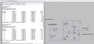
That looks pretty good. Almost zero distortion.
If you delete your 'OUT' on the sim and add a new 'vout' using the NET option (to label that trace or net) and if you run the sim but this time right click the circuit area workspace and select 'View Spice Output Log' you can read off the distortion. Whatever you label the net as must match the vout in that .four command although it is not case sensitive. Vout or vout is fine.


If you delete your 'OUT' on the sim and add a new 'vout' using the NET option (to label that trace or net) and if you run the sim but this time right click the circuit area workspace and select 'View Spice Output Log' you can read off the distortion. Whatever you label the net as must match the vout in that .four command although it is not case sensitive. Vout or vout is fine.
Thanks again ! the question now is how the calculation and the actual measurements will match
However what has captured me is the graphic output ... i like the peak and then nothing 🤔
I started from the assumption that distortion is to avoid as much as possible I guess this is not for tube lovers
for those just a single bjt would work better
However what has captured me is the graphic output ... i like the peak and then nothing 🤔
I started from the assumption that distortion is to avoid as much as possible I guess this is not for tube lovers
for those just a single bjt would work better
This circuit is interesting. So far, I have found that the unexpected low THD relies on a balance between the relationship between the load and the EF transistor, and between the CCS transistor collector impedance and the CCS bias impedance. The follower has a log component that is ~cancelled by an exponential component of the CCS. This means that the THD will not happen if the total load is not exactly 5K and is highly dependent on transistor behavior. More work is indicated to refine the implications.
Attachments
Good morning to Everyone !That looks pretty good. Almost zero distortion.
and with a high sensitivity power amp (i.e. an amp that can provide max power with more or less 300mV input) it looks even better 🤔
I cant run the last .asc file attached I do not know why
I can add some comments
- bjt selection is important
- even small change in resistors can result in notable differences perhaps even more than supply voltages
- no gain comes without pain
I also tried very basic diamond buffer but the 2nd harmonic distortion seems always present It is very difficult to lower it
If you have some interesting but simple unity gain schematics please kindly share them with me
I am not very tempted by complex schematics because i have a feeling that for buffers at least they can be not needed
It's not unusual for a specific combination of component values to give a spectacular result in LTSpice, but things become "normal" as soon as you touch even slightly one of the "dials" of your simulation. You've just come upon a combination where, in simulation, some non-linearity is cancelled exactly by some other non-linearity, but this is a simulation artifact and very unlikely to reflect in the real circuit.
For example, if you increase the load resistor to 20k (this will always decrease distortion in a real circuit), THD jumps from 0.000008% to 0.000124%, more than an order of magnitude worse. Or replace the transistor with pretty much any equivalent model (there's nothing "special" about the 2SD1782K) and things start to look much more realistic.
For example, if you increase the load resistor to 20k (this will always decrease distortion in a real circuit), THD jumps from 0.000008% to 0.000124%, more than an order of magnitude worse. Or replace the transistor with pretty much any equivalent model (there's nothing "special" about the 2SD1782K) and things start to look much more realistic.
Thank you very much I had that feeling 😕
Unfortunately this is not the case I think that simulation can help to choose the direction to go and provide a broad description of the circuit behaviour
My doubt is could a very simple circuit provide unity gain with very low THD when driving a 5kohm load or more complex topologies are needed ?
and can a diamond buffer provide very low THD ? i have been looking for schematics but they are of the test book kind or very very complex
with nothing in between When latins used to say in medio stat virtus (i.e. virtue stands in the middle)
This is very important and i can understand that If the circuit is intrinsically good it should provide similar results with equivalent bjtsOr replace the transistor with pretty much any equivalent model (there's nothing "special" about the 2SD1782K) and things start to look much more realistic
Unfortunately this is not the case I think that simulation can help to choose the direction to go and provide a broad description of the circuit behaviour
My doubt is could a very simple circuit provide unity gain with very low THD when driving a 5kohm load or more complex topologies are needed ?
and can a diamond buffer provide very low THD ? i have been looking for schematics but they are of the test book kind or very very complex
with nothing in between When latins used to say in medio stat virtus (i.e. virtue stands in the middle)
What happens when you try? Is there an error message?I cant run the last .asc file attached I do not know why
I would replace R5 by a dual series connected diode to reduce the effect of supply noise injection into the lower current source. R7 would need to be adapted to create the required current.
I highly recommend Douglas Self's "Small signal audio design", in his chapter about discrete transistor circuitry he analyzes and provides real world measurements for a number of unity gain buffers, starting with the simple, one-transistor emitter follower and adding complexity to it step by step up to an LTP with 5 transistors plus two CCSs, each step improving performance with respect to the previous one. Check it out, I'm sure you'll find something suitable there.Thank you very much I had that feeling 😕
This is very important and i can understand that If the circuit is intrinsically good it should provide similar results with equivalent bjts
Unfortunately this is not the case I think that simulation can help to choose the direction to go and provide a broad description of the circuit behaviour
My doubt is could a very simple circuit provide unity gain with very low THD when driving a 5kohm load or more complex topologies are needed ?
and can a diamond buffer provide very low THD ? i have been looking for schematics but they are of the test book kind or very very complex
with nothing in between When latins used to say in medio stat virtus (i.e. virtue stands in the middle)
That's a very strange circuit imo 🙂 The output impedance is a bit high meaning it can not drive low impedance loads very well and given the supply voltages it should excel at that. The output drops significantly at just a couple of milliamps loading.
You'll get a feel of knowing when things look right or not. For example I managed to get around 3.6Gv (Giga) spikes from one of the buffers we were playing with earlier. I can't remember which one and what I was doing but that was a non valid result.
Remember the 741 example and its FFT that I thought looked 'wrong' and how the reason was it running at zero bias current
How do you know if the outcome from the sim is more or less dependable ? are there any general checks to carry out ?
You'll get a feel of knowing when things look right or not. For example I managed to get around 3.6Gv (Giga) spikes from one of the buffers we were playing with earlier. I can't remember which one and what I was doing but that was a non valid result.
Remember the 741 example and its FFT that I thought looked 'wrong' and how the reason was it running at zero bias current
Yes indeed I have decided to change the test load to 600 ohm and actually the performance drop considerablyThat's a very strange circuit imo 🙂 The output impedance is a bit high meaning it can not drive low impedance loads very well and given the supply voltages it should excel at that. The output drops significantly at just a couple of milliamps loading.
I wonder if i have to add also a little capacitance to the test load like 200pF Some power amps could have a capacitive input ?
Anyway usually to drive a power amp to full max 2V are needed They are not an headphone or a more heavy load But I will make some changes
To have a power amp with high sensitivity high Zin and low input capacitance for sure makes things much easier
Thank you very much again. I will stop playing with weird circuits even if they look very tempting in their originality and simplicityYou'll get a feel of knowing when things look right or not. For example I managed to get around 3.6Gv (Giga) spikes from one of the buffers we were playing with earlier. I can't remember which one and what I was doing but that was a non valid result.
Remember the 741 example and its FFT that I thought looked 'wrong' and how the reason was it running at zero bias current
Maybe for a buffer it is just to find the right diamond buffer. I understand that in some cases it can drive even headphones
I like it a lot from an aesthetic point of view One of the fundamental characteristics of beauty is symmetry after all
I am working on one called HOS 100
https://www.sciencedirect.com/topics/engineering/loop-amplifier
https://ars.els-cdn.com/content/image/3-s2.0-B978075068703400002X-f02-01-9780750687034.gif
With any circuit or project you should set out your own design goals, what you want it to do. Write down your own specification, the supply voltage, signal levels and so on.
Always a good idea. You should also test using squarewaves at higher frequencies as that gives a lot of insight into problems and stability issues.I wonder if i have to add also a little capacitance to the test load like 200pF Some power amps could have a capacitive input ?
Get some strip board and a couple of 9 volt batteries and make some of your own. Try a simple opamp buffer, try a simple FET buffer and so on and see if you prefer one over another.Maybe for a buffer it is just to find the right diamond buffer. I understand that in some cases it can drive even headphones
- Home
- Design & Build
- Parts
- 2SD1782K _ is there a not smd equivalent ?