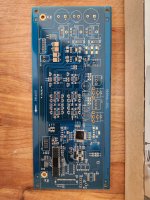
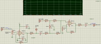
Marshall JCM 900 Reverb Issues

Short Story (kind of)

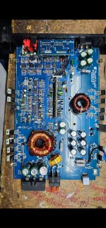
I have a Marshall JCM 900 4100 100W Dual Reverb head from aprx 1990/1991 and am trying to troubleshoot why the reverb on this amp head is not working.
See the long story for more verbose details including link to the preamp schematic, but unless I am missing something just about everything in this amp works including the reverb tanks, so my current troubleshooting assumption is that there is something wrong with the "Reverb Drive" portion of the preamp, hence why I am here.

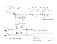
JCM900-reverb-drive.png


Please correct any of these assumptions, but my top level review of the "Reverb Drive" circuit is that the three op amps used before the reverb tank are voltage followers that are there to prepare both the impedance and the current to drive the actual reverb tank.

And if I were to probe connections with an oscope in that "Reverb Drive" portion of the circuit I would be able to see a sine wave on the scope. I am aware that the components of the drive portion of the circuit traditionally are the least likely to fail (in my opinion) being that they are just run of the mill resistors, caps, and common IC for opamps, and while none of them are blackened etc a PCB that is 30+ years old could have some issues or sometime things go bye bye w/o looking fried. I also acknowledge that the more common failures to reverb are tubes, tank, and rca connections, but I view I have got past that (see Long Story below), so I will happily eat crow if my assumption this opamp area is the culprit is inaccurate.

I "tried" to keep the short story short, so many other info about what I have done and got to this point may be answered in the long story. I very much appreciate you reading any part of this and pre thanks for any replies including "you are way off be careful and learn way more before you try again". This stuff is fun!


The plan, testing, and how I'm stuck
With the amplifier on and a 1khz sine wave playing through it and heard through the speaker cab, I placed a scope ground on the chassis and the other lead to the end of C16 where C16, C17, R24, and pin3 of the TL071 join assuming that a) this was the input to the reverb drive circuit and b) that the ac signal of the sine wave would be low voltage because either C14 or C16 decoupled the high voltage DC. Unlike a successful sine wave appearing on the scope when I tried the scope leads on the input jack and from reading the "send" from the fx loop, the end result on the scope for this start of the "Reverb Drive" was what I will refer to as low mv noise and not a sine wave. I had a similar noise reading on the black lead that goes to the reverb tank, but I was unclear if the scope leads should be pin/shield or pin/ground since the BK lead to the reverb tank doesn't go to ground it goes back to R25/R26. These tests had no reverb tank connected and the BK and RD leads were loose in the event that makes these tests invalid.

My plan going in was that the connection at C16/C16/R24 was going to work OK on the scope and then the problem lay ahead in the circuit, but since it did not work I'm here seeking clarification on some additional items.

My reading of the schematic, the connection from R20 to R22 that goes around the reverb drive/recovery is for the dry signal to go to and why the amp works w/o reverb and that connection between R20 to R22 goes only in that direction and its not a "negative feedback loop".
❔ I should be able to put the scope between R20 and R22 and see an ac only (since DC decoupled) on the scope and should see a clean sine wave right?
❔ I should also be able to see a clean sine wave on any of these points too right?
Intersection of C14/R20/R23 with scope ground lead to chassis
Either side of R27 with scope ground lead to chassis
Either side of R28 with scope ground lead to chassis
Either side of R29 with scope ground lead to chassis
Unsure R25/R26 intersection should have a sine wav.
It is my understanding that I "could" see a sine wave at the intersection of C14 and R3, but that would have high DC voltage on it so I am preferring to stay clear of that (I know I can change the DC coupling, but avoiding for safety lower risk and not blowing up my old scope).

❔ Does the reverb tank have to be connected to test the "Reverb Drive" portion of the circuit?

❔ Please confirm that all three op amps are preparing current and that the two MC1458 aren't setup to do a push pull or inversion thing where one is handling one side of the polarity. I am basically just asking for ways to prove what works and doesn't and not necessarily a reason why this circuit is a bad design as outlined in other posts here on diyAudio.

❔ Please confirm that my secondary reverb tank that does have a different input impedance would actually be a better tank to try since it would require the drive part of the circuit to produce less current. It doesn't work either, so I am looking for confirmation that it should/could work if the amp worked.

❔ Please provide any suggestions on places to check with DMM or scope to help diagnose this issue.

❔ Please provide any background as my concern on the tip shield being isolated and feeding back to R25/R26 and not ground on the BK going to the reverb tank and how that makes it less easy for me to understand how to test that connection.


Long Story

I have a JCM 900 4100 100W Dual Reverb from aprx 1990/1991.
Everything about it is in working order except the reverb (both channel gain, both channel volume, bass, mid, treble, presense, fx loop, footswitch are all OK).

I have an seldom used background in electronics, but no specialty in guitar amp (and am aware of the safety concerns of the high voltages in such amps).

Below are the steps I used to troubleshoot it.

Troubleshooting steps...
  1. There is zero reverb sound with the amp. None. Footswitch or not. Reverb 10 or 0. Both channels have their own reverb setting. Zero. If I twang the springs in the reverb tank with a chopstick they can be heard.
  2. The springs in the tank are in tact (four supporting floaters and four main plate springs)
  3. The connections to the RCA jacks are in tact using a beep on multimeter (tip and ring on both red and black cables)
  4. The connections to the transducers in the reverb tank seem reasonable in tact (no known way to test those)
  5. If I remove the tank and then connect it to my behringer umc1820 audio interface headphone output to the tank input and tank output to an input on my audio interface, a previously recorded guitar DI "sounds like it has reverb", this implies the tank is likely OK.
  6. Playing the same guitar DI through the headphone audio interface output and connected to the red RCA (what would be the out from the reverb tank) on the amp itself plays and can be heard clean through the amp. Both reverb pots on the amp then act like a volume knob for this external sourced input, including turning on/off when using the reverb footswitch. This makes me assume the return connections, footswitch, etc are OK.
  7. Playing the actual guitar through the amp input and then taking the black RCA (what would be the input to the reverb tank) and then connecting that to my audio interface does get some guitar input albeit needing to really crank the inputs on the audio interface and gain on the amp to hear/detect it. I barely call this a pass.
  8. I don't have an impedance meter, but the DC resistance of the tank is about 50 on the input and 200 on the output.
  9. The fx loop is operational
  10. Everything is the same after doing all permutations for the positions of the three 12AX7 pre amp tubes.
  11. The behavior is the same with another reverb tank I acquired. The tank is not an exact match however. My 8DB2C1D spec is 310/2575 input output impedance and the second tank I acquired is 600/2575. Is that really enough of a difference to hear "nothing"?

The numbers on the reverb tank are Accutronics 8DB2C1D
The numbers on the back of the amp are Y37594
The sticker on the side of the amp chassis implies March 1990 creation.

Looking at the schematic everything before the "Reverb Drive" section including the tone stack, presence, fx loop, V1a, V1b, V2a and everything after the "Reverb Drive" including the V2b, V3, power amp and putting an external audio input into the red return cable where it can be heard, adheres to the per channel attenuation from each reverb pot, it leaves me to believe that the reverb drive circuit is whacky since the BK input cables beeps pin and shield with a continuity DMM. There isn't much too the "Reverb Drive" section as its a couple of op amps TL071 and MC1458. Visually inspecting the top of of the board, none of the components look fried or problematic.

All of the components related to the reverb drive circuit pass a continuity test making the assumption that there may not be a PCB trace issue.
All of the resistors related to the reverb drive get expected ohm values within range noting the check was done with DMM on an in circuit reading.
I didn't check the caps as I am unaware of how to test those in circuit and was not about to yank those off the PCB yet. I didn't check any voltages to the IC pins while the amp was on yet (see above for the one test I tried and failed, stopped, then posted this post).

Testing was done by playing a 1khz sine wav file through computer umc 1820 audio interface out of its headphone output into the amp. The tone can be heard through the amp.
A scope successfully "sees" the 1khz sine wave at the input jack to the amp and if the scope reads the values from the FX loop Send.

I did not receive a sine wave at the C16/C16/R24 connection, so I'm here to get some clarification on how to test things further.

The preamp and power amp tubes are not original but they are 30+ years old as are the filter caps, etc. They do not appear to be microphonic.
Since I can "hear" the other aspects of the amp and swapping order of the preamp tubes makes no difference, it appears the tubes are in working order for their age.
Once I solve this reverb problem, I have additional questions/threads related to other aspects of this relic (for example there is either a very low transformer or filter cap hum can be heard not through the speaker).

The oscope I have access to probably is a dinosaur. It is an analog BK Precision 2160. It works minus any waveform I see moves to the left like an old school typewriter so I haven't found a way to have it lock in place.


References that got me here

JCM 900 Preamp Schematic from 1990
(I feel this is the schematic for my JCM900 based on date)

DIY Audio forum post from Gonecat that really helped me so far
(This forum post from this group here was very informative)
Gonecat,JMFahey,wg_ski,wahab,dotneck335 all were very helpful.


More Marshall Schematics

Marshall Guitar Amp Forum topic related to the same reverb tank I have

You Tube from Uncle Doug that helped me remember how to use an oscope

You Tube Uncle Doug another good video

You Tube Headfirst Amps showing examples of using an oscope on a tube guitar amp

Rob Elliot - Spring Reverb Unit For Guitar or Keyboards

Rob Elliot - Care and Feeding of Spring Reverb Tanks


JCM900-test-rig.png

Super Pensil 12

Hi all,
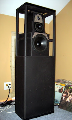
I have built a pair of a Super Pensils 12, on Alpair 12p. But I`am not happy with the sound. They sounds very bright, pain sparky high range, with poor mids and average low end. That is after about 200h of playing. So I have a question to the pensils owners/users: are you got the same experience? What is best aplifier to pair with Alpair 12p? Do you have in you`re pensils any kind of baffle correction?
Thx

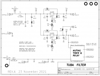
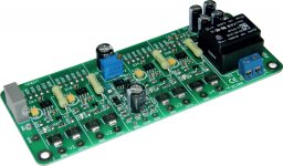
Tuba SMPS filter: two linear regulators inside VFET/Theseus chassis; incl thump kill

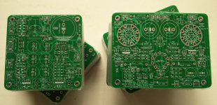
This Tuba PCB contains both an LC filter, to get rid of >50 kHz SMPS hash noise; AND also a of pair linear voltage regulators, to get rid of 100 Hz / 120 Hz hum. It's 2X filters. And just as 2X4 lumber is called two-by-four, this board is two-by-filters. Common mis-pronunciation is "two buh four" aka "tuba four". This board is thus "two buh filter" aka "tuba filter". Yes I know: too much information.

Each amplifier channel gets its own linear regulator, so Tuba provides an almost-dual-mono power supply arrangement. The left channel has no idea what the right channel is doing, or how loudly, so you get better stereo separation. Among other dual mono benefits.

The key component which makes Tuba possible, is the LD1084 voltage regulator IC from ST Microelectronics. It's a 5 ampere, low dropout regulator, which gives excellent hum reduction (>60 dB @ 100 Hz) without dropping much supply voltage. That's the second, downstream filter.

The first, upstream, filter is a critically damped LC network, using an inductor whose DC resistance is only 0.067 ohms. Even at the SMPS max rated current (4.4 amps), it drops less than 0.3 volts. This is paired with a "DC Link" polypropylene film capacitor, for lowest possible ESR. I suggest you actively consider the Epcos B32653A4105 , or if that's not available, the Kemet R75GI41005 . Both have truly mind boggling specs for dV/dt. The LC resonant circuit is critically damped by C2 and R1, reducing its Q well below 0.5, thereby eliminating any possibility of ringing.

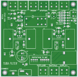
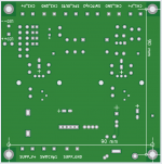
Gerbers are attached below; I very strongly recommend that you order PCBs with double thickness copper ("2 ounce copper"). There's nearly 5 amperes flowing in these traces! Make them thick and let the board run cool, run safe.

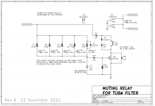
There is also a thump prevention relay circuit, on page 2 of the schematics. It is just a slightly fancier implementation of the thump preventer on the N-channel VFET supply filter board, designed by Nelson Pass. The same two-pole switch ("DPST") from the Nch VFET filter board is used. One pole turns power on and off, the other pole gives the thump preventer circuit a warning that the supply is about to collapse Right This Moment.

The speakers are muted "instantly" (with no delay) at power off. And the speakers are only un-muted after a long and leisurely delay from power on. PCB jumper options J9 thru J12 let you, the builder, choose the un-mute delay after power on: either 1, 5, 10, 15, or 20 seconds. Both of the beta testers set their PCBs for 10 seconds. And both were so happy with the results, they didn't bother to try the other delay options.

Tuba's choice of relay is mostly dictated by what parts are on the shelf today and not backordered for 24 months. That means: avoid the high demand relays (with 12 volt coils) and use the low demand relays (with 24 volt coils). Also avoid the small and cute, low profile relays; instead, use the big clunky ones that take up too much PCB realestate and are too tall. So I chose 653-G2R-24-DC24. Other relays that fit the board and work well are 655-RTE24024F and 651-2961192 .

The board fits inside the Modushop VFET chassis and its mounting holes align with the ventilation slots on the bottom cover, so you don't need to do any drilling. Its mounting holes are also aligned on the same 10 x 10 mm grid as the standard steel baseplate of the Modushop non-VFET chassis such as the Deluxe.

CAUTION

The Tuba filter is definitely NOT an appropriate project for a beginning or junior-intermediate builder. There's quite a few amperes of current flowing, and a very real possibility of destroying components by setting the board up incorrectly. It's also possible to ruin the board merely by adjusting it incorrectly (!) So unless you are a confident, experienced, knowledgeable builder -- don't mess with Tuba. Let someone else blow up their lab and their one of a kind VFET amp.

Because Tuba is a project for advanced hobbyists only, there isn't much more documentation than you see here; no "training wheels" build guides or Mouser shipping carts or troubleshooting tutorials. If you think you need those, maybe Tuba isn't the right project for you just yet.

ADJUSTING THE TRIMMERS: IT'S ALL ABOUT THE IN-TO-OUT VOLTAGE DROP

Find the three test points "TP1" , "TP2" , and "TP3" on both the schematic and the PCB. Adjusting the trimmers depends critically upon the voltages between these points. Solder a piece of 22AWG solid-core wire, sticking up about 1cm above the PCB, in each of those three places. Or use explicit "test pin" parts made by Keystone or Harwin. And get out your most accurate digital voltmeter.

Before you ever apply power to the Tuba board, turn both trimmer knobs ("VR1" and "VR2") all the way clockwise, to the right. This commands the LD1084 regulators to set their output voltage to the maximum possible value. Aha! Maximum Vout gives minimum (in-to-out) voltage drop.

With no load attached, and certainly with no front end boards or amp channel boards attached, connect Tuba to the on-off switch and to the Mean Well SMPS. Turn it on and wait 60 seconds. While you're waiting you'll hear the muting relay click; that's the un-mute delay. If you don't see any flames or smell any smoking parts, proceed.

Connect your DVM positive lead to TP1 using crocodile clips. Connect DVM negative lead to TP2 using crocodile clips. Now slowly turn trimmer VR1 counterclockwise while watching the voltmeter. Keep turning until the meter reads 2.0 volts from TP1 to TP2. That's the in-to-out voltage drop of the CH1 regulator. Congratulations.

Now move the DVM negative lead to TP3 instead of TP2. Slowly turn trimmer VR2 counterclockwise while watching the voltmeter. Keep turning until the meter reads 2.0 volts from TP1 to TP3. That's the in-to-out voltage drop of the CH2 regulator. Congratulations. You've completed phase 1 of the adjustment. Now you can finish wiring up Tuba's DC outputs

PHASE 2 OF ADJUSTING THE TRIMMERS: WITH ALL BOARDS POWERED

After you've connected all of the wiring among all of the PCBs, it's time to perform the final adjustments on VR1 and VR2. Start by attaching your DVM to TP1 and TP2, and turning the amplifier on. Wait 60 seconds. If you don't see any flames or smell any smoking parts, proceed.

Check the in-to-out voltage drop from TP1 to TP2. Connecting the high power, class-A amplifier boards to the SMPS, has probably caused a change in this voltage. It's probably not 2.0 volts now, and that's normal. Slooooowly turn VR1's knob to return the in-to-out voltage back to 2.0 volts.

If turning the knob a little bit (1/4 turn) has no effect: STOP!! Your setup is somehow wrong. Your meter is connected to the wrong test points, or you are dialling the wrong trimmer, (VR2 instead of VR1), or you've made some other mistake. Don't keep turning the knob, you'll probably destroy the Tuba board. Turn power off, unplug the power cord, and take a 15 minute break. Then double and triple check your setup.

Once CH1 has got 2.0 volts from in-to-out (i.e. from TP1 to TP2), move the meter lead from TP2 to TP3 and work on CH2. Slooooowly turn VR2's knob to return the in-to-out voltage back to 2.0 volts. Done! Victory!

TUBA CONTAINS TWO FILTERS . . . BUT NOTICE WHAT IT DOESN'T CONTAIN

Tuba doesn't include great big electrolytic capacitors. All it's got is 33 microfarads on the input and 33 microfarads on the output, of each regulator IC.

There simply isn't room.

In my opinion, thanks to the Class-A load current, Tuba doesn't actually _need_ great big electrolytic capacitors on either input or output. In my opinion, Tuba will work quite well with the Class-A VFET amps and deliver great sound. And Tuba will also annihilate that 100 Hz peak on your FFT plots, whether it was audible or not.
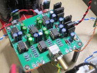
There are probably diyA members who don't agree; folks who firmly believe that Tuba's lack of 33,000 microfarad capacitors is a fatal flaw. Which is fine; simply accept that Tuba is definitely not what you want, and move on. Or maybe perform some experiments which attach additional supply capacitance somewhere else inside the chassis, but not on the Tuba filter PCB.

Or maybe, create a new and bigger filter PCB of your own, which does contain all of the electrolytic capacitors that you believe are necessary. Perhaps including some of the elements on Tuba (damped LC filter for >50 kHz noise // LD1084 voltage regulator for 100 Hz noise // thump prevention relay) or none of the elements on Tuba. It's your drafting table, draw up whatever appeals to you.


_

Attachments

  • Like
Reactions: starcat

left channel goes out of Akai 255 tape deck

I am restoring an Akai GX 255 reel to reel. It's my first attempt at restoration so I am a nubi. The left channel did not work when I started and the first thing I replace where all the C 458 transistors with the suggested replacements. When I tested it out I had the left channel sounding good but in a few seconds I could hear pops and other noises and then the it went dead. Can anyone suggest where I might start looking for the problem?

Introduction

Hi everyone, my name is Caio, i've been into electronics and mainly audio since kid, and i recently graduated as an electronics technician due to my love for this area. I've build some amps and now i'm looking forward to begin in speaker build, having studied some topics for this.

I really enjoyed discovering this forum and now i pretend to ask and share audio informations here to find help and help the others!

Introduction

Hi Everyone,

My name is Tony. I've recently registered with the forum but have been doing DIY audio for a number of years. Most recently I've completed some open baffle speakers and an EAR834 phono clone. And a lot of turntable maintenance.... Right now I'm interested in DIY of quiet power supplies for tube and 5v electronics like raspi and usb dacs.

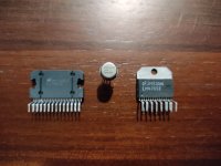
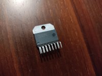
For Sale LME49713 LM4780 LM4765 discontinued parts from National

1727454388887.jpg
1729770464023.jpg


I have for sale this listed parts from National Semicondutor:
5 units - Lme49713 12€ each
5 units - LM4780 22€ each
3 units - LM4765 5€ each
5 units - LM4702C 25€ each

I have more parts from National that you could check here:
https://www.ebay.de/usr/rocksandsound
Regards

Attachments

  • 1727454527849.jpg
    1727454527849.jpg
    409.6 KB · Views: 305
  • 1729770464020.jpg
    1729770464020.jpg
    527.3 KB · Views: 75

Getting sponsorships

Hello guys,

I want to revive and combine two of my passions (DIY HiFi and making YT videos).

As part of this revival, I would like to contact a few audio equipment manufacturers, but unfortunately both my English and my lack of experience, especially with foreign companies, are standing in the way of this idea.

Are there any members here who have experience with both and can give me a little help?

Regards
Nik

Starting to treat this nightmare... Where to go?

Hi!


I got 489x537x253cm living/listening/cinema room, which means my 2 floorstanders on the longer wall stand pretty close to it (~20cm), and the L shaped couch stands pretty close to opposite wall (Probably that's why the ~35Hz rom mode is so huge - but this one is not my biggest concern of course)

https://amcoustics.com/tools/amroc?l=489&w=537&h=253&r60=0.6

1736207625484.png


1736210404990.png


With some luck I will squeeze around 7 pcs of 100x60cm/ (16cm/6.3" thick) absorbers in some corners of the room (for biggest air gap)

As I don't have a lot of space. I'm thinking about making some more 100x60cm absorbers for the ceiling (I fill fit only 10cm/4" thick absorbers + 8-10/3-4"cm air gap behind due to projector light)

Does it make sense to make the skinny ones for the ceiling?

If I make some. Whats the priority of ceiling locations? Should I focus on first reflections, or places over the speakers/ listener?


I'm thinking (have perfect space) about 2 Helmholtz Resonators - but I'll come back to it later, after the first part will be done.

Is it a good idea/plan at all?

Attachments

  • 1736208193747.png
    1736208193747.png
    194.3 KB · Views: 63

Crossover design services

Hello,

My first post after many years of lurking. I have been sketching up a pair of speakers with the drivers and come pretty far on how I would like to have it setup. Purifi 10" low(s) and bliesma mid / hi, sealed cab. However I would like to have the crossover part fully analog and no dsp on the signal path. Basicly I seem to have re-sketched MUM-10 speaker but without the dsp and hypex amps...
Both the skill and learning time needed to have proper crossover is way over my resources so I was wondering if there are any services available to design an crossover for a specific set of drivers in a specific cabinet.

thermistor for D3As to stop heater glow/flash

Hi, I am enjoying my little caesar 300b but one of the D3a driver valves flashes bright at start up. Can I use a thermistor on the heater circuit? Two D3A would draw .63A at 6.3v. How do I calculate which thermistor to use? Should I put in a bypass? I know there are better solutions out there but I have very little space to work with and a switch with a thermistor is very compact! Thanks.

Tube/valve amplifier Stability Simulation in LTSPICE

Hi all,
As I am doing my experiments with valves, many times I found my amplifiers oscillating.
To get a better insight of what is contributing to this, I have decided to simulate the circuit in LTSPICE, however the results I get make no sense at all.

Just to show an example, I designed a basic 2 stage 12AY7 pre-amp with the usual values for the resistors, capacitors, etc.
To do the analysis, I used the normal approach:
1 - Connected the amp in unitary feedback
2 - Broke the feedback puting a large resistor and capacitor, followed by a DC voltage source with DC=0 and AC=1
3 - AC analysis with 50 points per decade from 100Hz to 10MHz

Simulating the circuit gives me non-sense results. The poles should contribute with a 20dB/dec roll-off and 90deg/dec, which doesn't happen. It can be seen that the magnitude curve never crosses 0dB.

What am I doing wrong?
Do the models of the valves behave correctly for small signal?

Kind regards,
Pedro

fig1.png

Planet Audio AC3000.1D Output Driver board not turn on

Hello friends, sorry for the inconvenience. I am trying to repair this Planet Audio brand amplifier, Model AC3000.1D. I had already repaired some of this model, but this one in particular I could not get the output driver board to activate, I detected some shorted and open high and low channel transistors as well as an open 100 ohm resistor, but I cannot get it to activate. I appreciate your support, regards.

Attachments

  • Screenshot_20250109_153022_Gallery.jpg
    Screenshot_20250109_153022_Gallery.jpg
    512.3 KB · Views: 41
  • Screenshot_20250109_153105_Gallery.jpg
    Screenshot_20250109_153105_Gallery.jpg
    525.3 KB · Views: 44

PP47 finally pushing and pulling

It all started nearly 20 years ago, when Gary Pimm introduced his push-pull 47 DHP amp to the audiophile community. I must've entered a mid-life crisis (which still shows no sign of abating) and decided that I had to build that.

I've assembled most of what was needed, except OPTs; PTs and chokes came from Peter Dahl of Texas (yes, I decided on monoblocks), and I talked Gary, who displayed an angelic patience in answering all of my idiotic questions, into building the CCS and servo boards for me.

Then I developed cold feet. Or, perhaps, some thing have their own timing and are guided by their own stars. I remember getting involved with vintage amps and doubting my talents to build something of equal quality. Also, I didn't have a reasonably efficient pair of speakers to match with the PP47, but now having built 3 pairs of Coral Holy Basket based speakers (one bookshelf and two Frugel horns), I told myself 'now is the time'.

Gary's CCSs still have all the juice, and I'm following his advice to run it for a month before wiring in the servos. I'm using power switching supplies to feed DC to the 47s and finemet 14K OPT from Audiofeast/Terramoto which fit nicely under the chassis.

What can I say? My heavily modified Ampex 6973 monoblocks, the creme de la creme of vintage gear do not hold a candle to these PP47s. Which fills me with daring thoughts to sell the Ampexes along with a bunch of other gear and put the money toward a stereo version of PP47 ... Tabor perhaps ... SS Tabor (see the brazenness, and no, it shan't take two decades).

Anyway, here are the pics. And let's hope that they may trickle down to Gary's attention because his old email and another that I found are not delivering.

Attachments

  • PP_47_1.jpg
    PP_47_1.jpg
    252 KB · Views: 274
  • PP_47_2.jpg
    PP_47_2.jpg
    273.1 KB · Views: 268
  • PP_47_3.jpg
    PP_47_3.jpg
    257.1 KB · Views: 274

Tom Laird - new member

Hi,
I found your forum when looking to build a new power supply for my Arcam rDAC.
I am definately at the beginner level in electronics though I've built a few things in the past (a bass boost for a pair of Linn Kans, a scratch filter for a record deck, a new main board for my NVA amplifier when the wife pulled the speaker cables out without turning the amp off).
I am a draughtsman by trade working in the electronics industry, and latterly a layout engineer for Wolfson Microelectronics specialising in high end audio chips.
best regards
Tom Laird

Revox B77 Mk2 conversion from 1/4 (4 track) to 1/2 (2 track)

Hi everyone.
Owner of an early 90 (apparently 91) Revox B77 mk2 1/4 (4) track NShere. Recently serviced (electrolytics, pinch roller,motor bearings etc) and properly callibrated. All good, clean and perfectly working.
But i’m only using the machine for hybrid recording (just some passes of tracks for analog flavour), so i was thinking about converting it to 2 tracks. Since i don’t care about listening to 4 track tapes.

1) Am i correct to think that a 2 track normal speed machine is better for recording than a 4 track normal speed?
That mod seems pretty straightforward. Just swapping the headblocks, the oscillator pcbs and maybe changing few small things on the recording-reproduce pcbs. I can find cheap used headblocks and i can sell or swap mine. Mine is used in great condition so i expect to find one in similar condition as well.

2) Is the HS conversion so difficult? There are used hs capstans in good prices ( i can also sell mine or swap), but there is a debate about different placement on the b77 chassis (modification) or not (people say that it can be done on the same location on the chassis) , different motor (i could sell or swap if needed) or not (people say that thevsame motor works well, and it’s really confusing. Of course the speed pcb needs simple mods but that’s easy.
It’s hard to undersand what can be modded in a diy way, when most opinions come from “audiophile“ people (and ultra detailed techs) who don’t like “down and dirty” diy (i mean i wouldn’t mind a revox with extra heads as an echo - dub machine), and it’s hard to figure out what’s “snake oil” and what’s doable.
In my eyes normal revox machines are great workhorses and not precious collector’s items.

3) is there any advantage from changing the recording eq from nab to iec? Is it doable in an easy way (i’m based in europe- so my mains is 230v, 50hz- i read about a mod that mains frequency matters)?

Thanks in advance
  • Like
Reactions: krivium

  • Locked
Pioneer SA-420 Integrated Amp

I've had this for a couple of years but only used it in my garage system.
Out of interest I Googled it and was surprised to see the second hand value so I have decided to sell it.
There were several for sale @ £130 but before it goes on ebay, I'll offer it up here for £100 plus shipping.
It's in remarkable condition and the only thing that isn't original are the 3 input (function) lights. One of the bulbs had blown so I replaced all 3 with blue led's. They're a tad bright and I'm happy to change them for green ones if required but it really isn't a big deal.
It's a great sounding amp to be fair but I'll find something cheaper for the garage.
I'm in the North West UK.
Can post for around a tenner (UK).
Collection welcome and preferred.
PXL_20250110_183338210.jpgPXL_20250110_183347171.jpgPXL_20250110_183357630.jpgPXL_20250110_183406552.jpgPXL_20250110_183433881.jpg

Behringer EP2500 vs NX3000

Good morning guys. Anyway I'm undecided between these two amplifiers to connect near a 1500w rms bass face sub. Reading on various other forums and with tests in hand, both deliver about 2000w rms in bridge at 4 ohms. The fact is that I'm a bit undecided on which one to buy. Maybe for stability I would be more oriented towards the ep2500 which would then be an ep4000... I think the ep2500 would maintain lower frequencies for longer than a class D. I saw a video in which the behringer nx3000 (which would then be an inuke3000) was disassembled and there are basically 4 capacitors, it seems strange to me that it maintains all that power.... What do you think? My subwoofer is ground zero gzrw 12x spl https://www.ground-zero-audio.com/en/produkt/gzrw-12xspl/

Best tube amp for Acoustat 1+1

I bought my brother a restored pair of these amazing speakers. His local high-end guy convinced him to pair them with transistor amps because of their power requirements. However, his system now decidedly lacks fluidity and musicality and has a clinical, almost digital sound. When I fell in love with the 1+1s, I was driving them with an Audio Research D70. They sounded heavenly (at low levels). We only listen to classical and old jazz. Is there any tube amp that you can recommend with these?
Thank you, and happy holidays!

The Preference for Direct Radiators

Mitch asked a question in another thread which I think is the most interesting debate in audio right now:

In a nutshell, if two loudspeakers measure the same, why do people have a subjective preference for direct radiators?

Here's some background on this question, from my own perspective:

Seventeen years ago, I worked for one of those failing dot com companies. We didn't have any business, so I would show up to work and study patents all day long. It was a way to kill time and appear to be busy. Just sit at my desk staring at a technical doc for eight hours that looked like engineering work. That's when I started learning about horns, Tom Danley's stuff, Keele's stuff, etc.

I've built a ton of speakers over the years, nearly all with a horn or waveguide, but there's a consistent problem with nearly every one:

They can sound great with great recordings, but with bad recordings they sound mono.

Here's an example of what I mean:

IMG_0661.JPG


A few years back, I rented some Danley SH50s. They have a fairly flat frequency response and they're really well behaved in the phase domain.

vandersteen-3A_3.jpg


My reference speakers are Vandersteen. They have a fairly flat frequency response and they're really well behaved in the phase domain.

The Danley speakers cost about 20X as much as the Vandersteens. You can find the latter on Craigslist for $300, easily.

On an excellent recording, the SH50s were breathtaking. For instance, you can turn the lights off and put on a track with a really great soundstage, and the SH50 is one of those speakers where the image is almost holographic. Where the center is so solid it sounds like you have a center channel, and you can almost get a sense of "front to back" depth. The dynamics are far beyond anything you would ever need in a home.

The Vandersteen can't reach those highs, the stage is never as well defined and the dynamic limits are nowhere near as high.

But here's the crazy part - on most recordings, the Vandersteen's image sounds bigger than the SH50.

This is particularly noticeable if you listen to crummy recordings. I basically listen to podcasts, EDM, some 80s music, and some punk rock. I don't listen to jazz, or orchestral, or classical.

My 'hunch' is that the much wider directivity of the Vandersteens is 'lighting up' the room in a way that the SH50s can't. Basically the Vandy's can't extract all the information in a really good recording the way that the SH50s can, but the Vandy's are also 'glossing over' the bad qualities of many recordings.

I've built a lot of Unity horns for my car, and ran into a similar issue:

There were some recordings that sounded bigger than the car itself, but there were also many recordings where it sounded like I had a mono speaker sitting in the center of my dash. It's like buying a 2160P HDTV, then realizing that a lot of your favorite movies were filmed with a potato.

For Sale For Sale: Complete Ian Canada Streaming Stack

Hello Gentlemen,

I'm selling my fully functional Ian Canada Streaming stack, which was purchased directly from Ian. The entire setup is in excellent condition and will be shipped fully tracked with proper anti-static packing.

Asking Price: $400 (via PayPal)
This includes all items listed below, along with the licenses.
  1. PurePi II: Product Link
  2. FiFoPiMa V1.5: Product Link
  3. TransportPi AES: Product Link
  4. Monitor Pi: Product Link
  5. Raspberry Pi 4 (8GB RAM): Pre-installed with GentooPlayer OS (lifetime subscription), including CLTO and Diretta licenses.
  6. Acrylic Protection Cover
  7. All Accessories needed for stacking.
Notes:
  • Individual pictures of the items are posted for your reference.
  • Product links are provided for details on each item.
  • 18650 batteries are NOT included due to shipping restrictions.
Shipping Details:

  • Open to ship anywhere in the world at actuals.
  • I am okay to bear 50% of the shipping cost.
My Location: Bangalore (India)

If you're interested or have any questions, feel free to message me. Thanks for looking!!!

1736395505820.png
1736395505820.png

1736395589647.png
1736395589647.png

1736395656860.png
1736395656860.png

1736395704662.png

1736395732416.png

1736395772532.png

1736395829209.png
  • Like
Reactions: manniraj

midwoofer vs full range

I'm in the planning stage of my first multi driver speaker build. I've only ever built subwoofers prior to this so I'm in uncharted waters. I'm wanting to build a pair of 3 way speakers to go with my latest subwoofer build. Its a T-Line , quarterwave (down to the centimeter) and modeled strong well up past 100 Hz so the down low is covered. The initial plan was a 3 way setup 8" woofer, 4" mid and horn tweeter. My question is where it comes to the mids. Is it better to just buy a midwoofer or would a full range driver work better? I'm just trying to make sure every end of the spectrum is covered and aaybe learn a thing or 2 so an explanation of why one or the other would be ideal would be very much appreciated. I'm of the mindset of do one thing, do it well so I question the "full range" would have the same quality sound as a dedicated midwoofer and a tweeter handling the highs. Or am I misunderstanding what full range actually means. Thanks for your time

For Sale ACA Mini upgraded parts kits (caps, coil, & feet)

I ordered a number of modification parts for the ACA Mini based on @ClaudeG and @xhitespirit suggestions and want to pass along the option for a "parts kit" as I bought parts in larger quantities. Since I bought in "bulk", the price is right ($15) as long as I can ship within the continental US for around $5 via USPS ground. The total cost should be around $20, but will require a PM inquiry to be sure of final cost based on shipping. The 3D printed feet have various colors options I can provide.

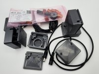
The kit will include:
  • 2qty: Panasonic ECW-FD2W335J PP caps (3.3uF / 450V) as DC decoupling output caps bypasses
  • 2qty: Nichicon UHW1E152MHD caps (1500uF / 25V) as PS bypasses
  • 1qty: Murata 1433428C coil for additional SMPS filtering
  • 4qty: Custom 3D printed chassis feet
  • 1 qty: 3D printed Murata coil box
  • 1qty: 1 meter 5.5x2.5 barrel connector extension power cord
20240711_202736.jpg


20241124_115359.jpg


I also have a bunch of PCBs for sale at super cheap prices if you want to combine the shipments.

Send me a PM with zip code for shipping estimate if you're interested including what color feet you'd like.

20241013_201233.jpg

Attachments

  • 20241207_184600.jpg
    20241207_184600.jpg
    480.4 KB · Views: 97
  • 20241013_192005.jpg
    20241013_192005.jpg
    302.3 KB · Views: 104

Dual Opposed Acoustic Suspension Subwoofer | GRS 12SW4HE x 2

Hi all,

Recently completed a build. It's a dual opposed sealed enclosure with some budget drivers. I wanted to experience and measure a dual opposed system to get a better idea of the vibration cancellation and the suitability of the design in the context of living furniture that happens to hide a subwoofer in the future (tables, end tables, coffee tables, ottoman, etc as subs in addition).

Dual Opposed Acoustic Suspension Subwoofer
GRS 12SW4HE Drivers x 2 (Series, 8 ohm, drivers in same phase but physically oriented to face opposite)
Sealed 3.7 Ft^3 Gross | Sealed 2.6 Ft^3 Net Internal (15mm Pine Plywood) | 3.07 ft^3 Effective Stuffed Volume
Qtc 0.770 (Simulated) | Qtc 0.919 (Effective Actual, Derived from Measurements)
500w Power Handling

Final_GRS12SW4HE_Dual_Opposed_Acoustic_Suspension_06062024.jpg


20240602_141009.jpg


Login to view embedded media
Very best,

Which contact cleaner to use? Getting very different advice online

Hi All,
I am currently fixing a Rotel RA-930AX. It now seems to be working fine, apart from a slight crackle on the left channel which is evident only when i turn the balance dial to the left. I have cleaned this multiple times using Servisol 10, but the problem remains. I have read online that Deoxit may be better to use, as it removes the oxidation on the fader, as well as cleans. However, there is also some debate over which deoxit to use. Some videos say use D5, while others say F5. Any advice? Would switching from servisol to deoxit likely fix this issue, or do i need to get in there an take the potentiometer apart to clean it properly? Thanks!

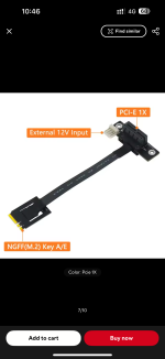
Help with installing a firewire PCIe card on Intel NUC5CPYH

I am trying to install a firewire PCIe card onto the Intel NUC5CPYH mini PC via an adapter connected to the M.2 slot (photo attached). I intend to use a firewire dac with this set up. This slot was previously used for a wifi card which was working ok. I understand that it is compatible with PCIe 1X standard.

The firewire card is Syba-pex30016 with TI XIO2213B chipset.

I have connected the card and provided external power into the power socket of the card.

The problem is that the NUC does not recognize the firewire card at all. In the bios setup of the NUC, it says nothing is populated in the M2 socket. Nothing show up in device manager of Windows 7.

The firewire card and the adapter are brand new.

I am wondering if anyone could give me some advice where to check for problem.

Attachments

  • IMG_2688.png
    IMG_2688.png
    363.6 KB · Views: 58

In search of special TRS to TRS mono 1/4" adapter

I used to have a few of these, but am having trouble finding them online - may have to just make them.

It's a special 1/4" TRS to 1/4" TRS adapter, missing the insulator between the tip & ring, with the ring being slightly longer to make up the difference.

Purpose: allow a stereo headset to be plugged into either a mono or stereo audio source, with mono always going to both speakers.

They may have been made for something else, but that's what I used them for...

1735614275682.png

Switching to individual tube bias - A couple of basic questions.

So I've found myself elbow deep in rebuilding this old arc vt60 amp for fun, and as an opportunity to learn more about tubes and how all this stuff works, so I appreciate commentary.

So this amp uses a single bias trimmer for each pair of output tubes. I would like to add individual adjustment, among other things. I've managed to find a few different ideas, and I'm hoping someone can set me on the right track.

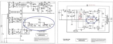
1.) Duplicate the bias adjustment circuit, and break the connection between R15 and R16, eliminate R18, add two new 1r resistors between each cathode and ground. (Blue circles on schematic)

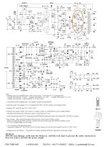
2.) Add some cathode adjustment, like they did in the vt65/clone amp, 5r6 with a 100r trimmer. (Orange circle on vt65 schematic)

3.) Order and play with something more esoteric, like an AB-Qi module.

What say you, wise experts?

Attachments

  • vt60-edited.jpg
    vt60-edited.jpg
    223.6 KB · Views: 118
  • vt65-edited.jpg
    vt65-edited.jpg
    346.4 KB · Views: 101
  • abqi.jpg
    abqi.jpg
    184.5 KB · Views: 105

Sanyo STK modules Ali or DIY?

Hello all.

Not that much discussion on STK components here, the general feel is that with the original designs out of production and stock for years, everyone avoids them if they can.

Is anyone keeping track of which models have reliable Chinese copies and what is pure junk ?

I ended up building my own copy for the STK8050, am currently working on a (complimentary) substitute for the STK2038B and have seen that there have been a couple of other projects on the STK voltage amplifier modules.

Which Sanyo (or Sanken) hybrid modules are really in need of a DIY project due to lack of existing reliable clones ?

Balanced Volume Controller / Line Stage

This is a series of high performance balanced active volume controls with differential input, ground-sensing output (goodbye cross-channel ground loops!), and a choice of analog or digital volume controls (sample Arduino sketches for the latter are included):
All versions feature:
  • Balanced differential input with excellent common mode rejection - works very well with single ended sources, too!
  • Output stage that can be configured as balanced (best for downstream stages with differential input) or ground sensing / ground cancelling (best if followed by a single-ended input referenced to its local ground - the vast majority of audio power amps are configured this way).
  • Compact (2.9x2.6in or 74x66mm) two layer PCB, all though hole parts (except WM8816/MAS6116 and MUSES72320, which only come in surface mount packages)
  • Can be part of an integrated amplifier (great with LM3886 or similar chipamp based power stages); an output stage of a DAC to form a "digital preamp"; with an input selector, a high performance balanced line stage / minimalist analog preamp.
The schematic is based on Bruno Putzey's Purist Balanced Preamp (aka BPPBP) from his article "The G Word, or How to Get Your Audio off the Ground", originally published in Linear Audio Vol.5. PCB design also follows Mr. Putzeys' method.

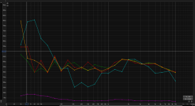
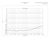
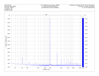
Attached are the schematic and measurements for the analog pot version. My soundcard (E-MU 0204) is not good enough to measure the distortion of this thing at 0.0005% at 1kHz - please look at the baseline plots of the soundcard with its input connect directly to its output. Also, note the difference in PSRR between NE5532 and LM4562.

The last plot is one ground referenced channel of a stereo LM3886 amplifier (with one power transformer and one power supply shared by both channels and the line stage) driven by this line stage in its ground sensing configuration. I used my own LM3886 PCBs.

UPDATE: boards are available at HiFiOcean.com.

UPDATE2: a single-ended volume control based on DS1882 is added - it includes a Firstwatt B1-style JFET buffer and a low-noise regulated power supply, all on 1.1x1.1in (28x28mm) board.

UPDATE3: Sample Arduino sketches to control any of the above mentioned digital volume controls are now available on GitHub.

Attachments

  • avc+s sch left ch.png
    avc+s sch left ch.png
    24 KB · Views: 7,547
  • SC loopback.png
    SC loopback.png
    37.2 KB · Views: 7,154
  • AVC balanced.png
    AVC balanced.png
    37.2 KB · Views: 5,954
  • thd+n 1kHz avc LM4562.png
    thd+n 1kHz avc LM4562.png
    37.4 KB · Views: 5,815
  • thd+n sc only.png
    thd+n sc only.png
    23.5 KB · Views: 5,778
  • thd+n avc.png
    thd+n avc.png
    22.9 KB · Views: 1,363
  • thd+n avc lm4562.png
    thd+n avc lm4562.png
    23.1 KB · Views: 1,255
  • AVC+LM3886 ground sensing.png
    AVC+LM3886 ground sensing.png
    39.1 KB · Views: 1,531
  • IMG_0732.JPG
    IMG_0732.JPG
    102.5 KB · Views: 3,867
  • IMG_0737.JPG
    IMG_0737.JPG
    86.9 KB · Views: 2,998
  • Like
Reactions: pbilous

Musings on THD

The total dynamic range of a THAT driver and receiver combo is over 21 bits, 20KHz bw, unweighted. They’re made for pro audio levels and systems. 128dB of DR is not reproducible in anything but a very special acoustic environment. However common mode noise down 75dB or so is.

You take your pick and apply technology that makes sense in the specific conditions.

IMO, bothering about THD below 0.01% is tilting at windmills because more than that is baked into all your recordings, and much, much more is added by your speakers. And it’s all masked by the music.
  • Like
Reactions: sawyers

Introduction!

Hey everyone! I guess this is my first post but I have been lurking for a while now. Thanks for all the information that you all have shared over the years! The speaker building community never ceases to amaze me! I have been building car subwoofers for a few years and recently started to develop more "Pro" level subs and have even made a few for "clients" after they hear my own system that I rent out at shows. Seems to be going well so far and I would not have made it this far without the community! I have also been working on my own full range horn speakers and got into 3d printing and CNC manufacturing to make my semi unique ideas come to life!

I can share some pictures of my designs if you are interested and maybe you can tear them apart a bit!

I do have a few questions for you all but I guess they can wait. Mainly regarding some DIY amps that while simple enough, are above my IQ apparently. I'll make a new thread for that possibly after some more digging!

Thanks!

Are any of the prebuilt amplifier modules on Amazon decent?

I'd like to buy one of the stereo amp PCBs that are on Amazon. I'd attach a sample but Amazon is crawling with examples, there are dozens of different offerings. The question is: Are any of them known to be at least "decent" in terms of quality?

I'm looking for a utility amp for the workshop and I'm thinking why not one of these modules? Ten or twenty Watts/ch is quite enough for me; but what's the trustworthy purchase? Thanks.

Aleph J cascoded three incarnations

Hi!

I made three types of wiring diagrams possible only to the precious advice of Zen Mod

1) Aleph J ZEN - IRFP150 - 30W

2) Aleph J ZEN - IRFP240 - 30W

3) Aleph J ZEN - IRFP150 - 60W

They have the front end as their common denominator.
1) type 1 is a 30W and has the advantage of being able to avoid MATCHING with IRFP150 that is equal of 2 x IRFP240 inside .
2) type 2 and 3 use the same PCB layout for both 30W and 60W (only the power devices, PSU and heat sink obviously change for 60W), both 24V to 32V RAIL able to operate.
Many thanks to Zen Mod
Antonio
  • Like
Reactions: Mikerodrig27

GB: EL34 Baby Huey Amp and PSU MK2 PCB

Hi. As discussed on the EL34 Baby Huey Amplifier thread, I'm starting a new GB for the amplifier PCB and separate supply, Mk2.

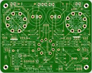
The AMP PCB is designed to install the tube from the back, version of this pcb is MK2 Rev 1.5-2, bottom, dated 14-07-2019, see schematic. The MK2 version has no power supplies built-in, you need the separate Power Supply PCB. As suggested I corrected R14/R15 to 1K/2W, the correct value for the EL34 tube.
You need One (1) AMP PCB per channel, Two (2) for a stereo amplifier.

The Separate Power Supply PCB is version MK2, Rev 1.5-1, dated 23-07-2019
You need one One (1) PSU for two channels...

Check the PCB images for dimensions.

Add your name to the list and send me a private email. Then I will contact you to get your full name, full shipping address and private email to reach you.
Once we have an idea how many members we have we can have an idea of the pcb price. Prices should be similar to previous GB...

We will see how it goes...Thanks
SB

March 19th, 2021 UPDATE
This GB is now CLOSED


March 20th, one kit still available, one buyer changed his mind...


July 12th, Will place a small pcb order this week for a few extra kits. Already sent email to the few that were interested so far. If interested let me know.


August 5th, Received second batch of PCB and already starting shipping. Still have a few extra kits, if interested let me know.
August 20th, Only one kit left, if interested let me know.

Finally ordered the output transformers for the amp, so I'll be able to test my own PCB. and received the power trnasformer as well.

Sept 9th, No more kit left, but I'm ordeirng a new batch with some other projects, so if interested let me know.
Sept 20th, received third batch of PCB and already starting shipping of two kits. if interested let me know.

Attachments

Coral BX-200 tweeter

Hello all,

First time poster, so please be kind and patient.

I've inherited a pair of Coral BX-200 speakers. They're going to be my first attempt at a refurb. However, one of the tweeters is blown, based on initial sound tests. Would anyone know where I could find a replacement? Or could I replace both tweeters with more modern ones?

Specs:

CORAL BX-200

Many thanks,

simao

Dayton4 - DIY Low Budget/Good Sound Small 2 Ways - With CNC Enclosure

DAYTON4 - BUGET SMALL 2 WAYS

ORIGINAL DESIGN BY DUANE BROWN

You can find his design including original enclosure size, crossover components and everything related on Mr Duane Brown page:

https://duanebrowndesigns.blogspot.com/2018/10/getting-your-feet-wet-in-diy-speakers.html?m=1

You can also find the several reviews and variations on this design on several forums...including good comments from really good speaker designers, and also for the Dayton Audio TCP115-4 4” woofer that is used on this 2 way speaker known by the bass it can produce.


The reasons to choose this design where easy:

*A small 2 way with flat response, details and clarity. There is plenty of images with the frequency response and such.
*Components where cheap…i´m in south america so shipping cost are also take in account.
*Few components crossover… i read/think too much about the changes that every electrical component/equipment adds to the sound, this is a series crossover, only 4 parts.
*Small size and Area to be fulfilled… Just a small living room.
*Good reviews for design and components… from designers on other forums and the drivers itself on youtube.
*They are been made as a gift for my Dad (73)…so he doesn't need to get a Beryllium tweeter either way (Even when he deserve it..i cannot afford it)
*Also for my to compare it with a full range MarkAudio speaker that i build on planet10 mFonken enclosure that i REALLY like as was my first diy speaker and i'm still impress on how a good FR driver with no crossover whatsoever sounds that good.

DRIVERS:
Woofer Dayton Audio TCP115-4 4”
Tweeter Dayton Audio ND16FA-6 5/8”

CROSSOVER:
3 OHM 10W RESISTOR
0.20mH 18 AWG COIL
8.0uF CAPACITOR
1.0uF CAPACITOR

ENCLOSURE

I do changes in the cabinet outside dimensions, trying to apply the theory on Direct Radiator Loudspeaker Enclosures by Olson Harry.. also to impress my Dad on what carpentry with cnc can do now days.. the internal dimension where the same that other builder used on Mr Duane design and call it the ¨Deluxe version¨ as he made it a litter bigger and change the crossover components to polypropylene versions on the capacitors. The original enclosure is 8” tall, 6”wide, and 8.5” deep.
The enclosure material is 18mm pine plywood, lining the internal walls with recycled denim, the material used on car trunks/carpets.

I think i don't have anything more to cover so here some pictures of the build process=


FLAT PACK..To call it in that way

20241202_154828.jpg


20241202_154711.jpg


20241202_154805.jpg

The letters on the top are my dad´s name initial..in case you are wondering


Baffle -- recess cut for driver to be flush mount and release on back to let it flow

20241202_165258.jpg


20241202_165249.jpg


Binding post cut manually done, as the cnc guy ¨forgot¨to do it...not finished in this photo

20241202_165217.jpg


Glued together - I'm missing a photo with the internal material--next time i post

20241202_174150.jpg


20241202_174201.jpg


Crossover assembly - testing - finished

20231206_174314 (1).jpg


20231219_150253.jpg


and the Ufoken enclosure with Markaudio CHR-70.3 that i did as my first diy speaker that i want to compare against this 2way design

ufoken.jpg


I will post more picture as i progress with the process.. hope this week is going to be complete already.
And by the way English is not my native/first lenguage in case it wasn't noticed

Hi everyone. I,m sure I’ve posted on here over the years but just had to reset password

I was in the audio industry for quite a few years. I am both an audiophile who enjoys music on my modern gear, but love my vintage 1970s, 80,s gear even more. I have restored many amps, cassette decks, reel to reels, etc. and have lots of Teac along with other Japanese brands.
  • Like
Reactions: Freedom666

KiCAD Kick start

During the last few years I have been playing a little with KiCAD and have some drawings of more and less well known commercial designs, as well as designs from diyAudio and other forums. Many boards have been routed and a few have been produced. So far, some are being built, but only the Pioneer Superlinear has been tested by a friend of mine. Worked fine.

Now I wonder if someone is interrested in a KiCAD Kick start (I know I would, when I started) by exploring my KiCAD project folders? You may download everything or just a little. Use it, misuse it, alter it.... no copyrights on my part.

What I don't know is if there is a time limit or download limit to these Dropbox links. Anyway, we'll find out.

If the interrest is there, I will post the link.

A few samples of produced PCBs:

Order_02_C.jpg


Cheers!

🙂 morten

Fixing a high end record player, a Fischer Price 820 !

Today, an unusual fix (for hifi aficionados like we are), a Fischer Price 820 toy record player.

Someone brought it to me, not working. Not producing any sound from the speaker, more precisely. This machine can work both with 4 C 1.5V batteries and with a 6V DC external power (+ inside). That’s the reason why he took it to me. He had tried to power it with an external PSU, but not knowing its voltage nor the polarity of the plug. Therefore, it has produced a plop and smoke when he lifted the arm up.

The motor works, the platter turns when you lift the arm (like it should), but that’s all I know.

First, 5 screws to open the plastic case. We can see a small PCB, two contact relays, the (small) motor, and that’s nearly all you get inside. Which is enough. Everything else is plastic, rather good quality one. A robust toy.

1736177737642.png


On the component side of the dirty PCB, I see immediately the 220µF/10 capacitor which has blown up (center of the photo below). Easy. That size, only got a 470µF/16, it will do. Reflowing some solder joints, little bit of PCB cleaning, resoldering all wires. Give a try, not working. Ah.

1736177824537.png


It’s more complicated than I thought. Got to investigate a little bit more. I like it, kind of too simple if there's no sweat at all...

First, try the speaker on its own. It works. Then going backwards, I injected a 100 mV 10 kHz sinus signal on the PCB points corresponding to the red and black wires coming from the piezo pickup and I could hear some sound coming from the speaker. So at least I knew that the amplifier part of the circuit was OK.
So the problem was probably with the wires from the pickup to the PCB themselves. And it’s the tricky part, because to access to the pickup wires is rather uneasy, to say the least.

I had to unsolder the two wires on the PCB to let some room to get the arm out, then take it out (circlips, platic parts and so). This step is rather uncomplicated. Next one is more challenging. Once I had the arm apart, obliged to cut delicately between the superior and inferior plastic parts of the arm with a cutter to separate them and access to the pickup connections themselves (no screws, sorry). Continuity was OK through each wire, but. But of the 2 contacts of the pickup itself to one of the wire, no continuity.

There is a small metal contact linked to the wire that is supposed to make contact with the pickup.

1736177898111.png


One of them was not bent enough to be able to touch the pickup contact. I bent it more with a very small plier, and then, there was continuity again. I tested roughly with my finger gently brushing the tip, and I could hear a sound from the speaker. OK, I like that better.

After I cleaned all the moving parts in the arm and greased them lightly, I glued the inferior and superior parts of the arm, reinstalled the whole thing back, and had a try with a record. Everything was right, nearly good sound. Tuning of the 45rpm and 33 rpm speeds with the two dedicated trimmers, general cleaning, screws back.

video Fischer Price 820 (YouTube)

That’s it.

That post helped me a lot : fisher-price-816-record-player-repair
  • Like
Reactions: phase

Best Practice for measuring burst decay

Hi All,

How do you measure bust decay? what are the best practices?

I am using a measurement mic and the REW Spectrogram tab set to burst decay.

I am measuring indoors. (probably a red flag)

I have tried measuring at 50cm, the burst decay is full of noise from room reflections,
I have tried measuring at 5mm from dust cap, there are no resonances visible (I'm pretty sure the enclosure has some resonance)
I have tried measuring at 5mm from the side panel, room reflections dominate the signal and no resonances are visible through the noise.

Do I need an anechoic chamber or an NFS to do this? or is there a clever way of doing it indoors? I have also considered buying one of those portable power station things and taking the measurements in a park, away from all reflective surfaces. The last option doesn't sound very fun, especially as I am trying to compare 4 enclosures using the same drivers so I will be pulling speakers apart in a park...

Thanks in advance for your help,

For Sale Oppo UDP-203 Linear Power supply Upgrade, 115V version

FS original UDP-203 Linear upgrade power supply, 115V Version, assembled and tested, bought directly from https://www.oppomod.com/

Replace the original Oppo switching power supply, to eliminate all the HF noise induced by the Switching supply, for better audio and image quality. Easy to install, just remove the original supply pcb, screw in and connect the new supply, piece of cake...

Still sell for 360U$, see https://www.oppomod.com/

Asking 200U$ + shipping + Paypal 3.5%

Attachments

  • 20250109_132219.jpg
    20250109_132219.jpg
    122.8 KB · Views: 55

First Watt Modules Concept

I'd like an amp rig that's based on swappable circuit modules that you can "roll" like tubes. DIY First Watt circuits are an obvious choice for this concept as there are so many circuits to choose from. Other circuits will be great too, JLH, etc. If I create formfactor for this will Papa disavow?

Server rack or maybe Eurorack with pins would be a general concept. For example, a 1U chassis with active cooling, universal PSU and swappable amp/preamp circuits.
  • Like
Reactions: von Ah

Fully digital DC to DC converter XL4015 based

For those who looking for something like this

Attachments

For Sale Borbely Phono PCB EB-804/419, and All-FET Low Noise Regs EB-707/418

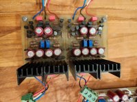
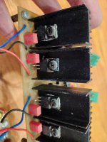
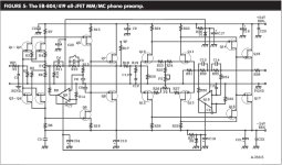
For sale, Borbely Borbely Phono PCB EB-804/419, and All-FET Low Noise Regs EB-707/418, The phono is a two sections, MC front end, and then MM section, all similar using the now well known K170/J74 front end JFET, AD820 Hi-end op-amp for servo, all vishay resistors, Wima cap, etc. A great phono section,

and as for supply the all discrete All-FET Low Noise Regs EB-707/418, with as for final the famous K2013/J313!

Two pcb comes fully assembled and tested, bought them some years ago from an other member.

Asking 175U$ for the phono section and 100U$ for the All-FET regulators + shipping and 3.5% Paypal fee

Just with the cost of the pair of K2013/J313 is it a very low price!

You just need a power supply and enclosure for a killer phono section.

Kit comes with all the docs, schematics, Borbely articles, detailled BOM, etc...

Attachments

  • 20250108_195539.jpg
    20250108_195539.jpg
    332.7 KB · Views: 137
  • 20250108_195554.jpg
    20250108_195554.jpg
    322.2 KB · Views: 115
  • 20250108_195608.jpg
    20250108_195608.jpg
    253.1 KB · Views: 124
  • Phono_Schematic.JPG
    Phono_Schematic.JPG
    123.2 KB · Views: 134

New Pro audio guy saying hello

Hello everyone. First a little background on me. I’ve been into audio since I was a kid. From playing guitar with my grandpa to getting my first boombox to modifying audio in my first vehicle. This lead me to a career in car audio a job that I loved and then lead to me doing live sound. I now run production for bands and DJs and am here hoping to learn more. Mostly in the PA realm but other things as well.

Greetings from the 'burgh

Hi all. My background is mainly in software and audio recording/production, but I started my career in electronics and have always like circuit design and anything related to audio especially with guitar amps since I used to also be an avid guitar player. While troubleshooting an issue with my guitar amp recently, I came across this forum and not only are there a vast array of topics on this forum, I was very happy to see that it is a helpful community also and looks like there are many members willing to share and help each other out.


-Brandon

Hello All

New member here. Thanks for the add. I'm also new to diy audio repairs and audio gear collecting. I'm currently listening to mostly vinyl on my SL 1600, running it through a NAD 1240 preamp into a Sansui 5000A. I'm still figuring out the speaker situation. I currently run Sansui SP-3000's on A, pioneer cs-66a's on B, and am rotating some Bose 6.2 or Minimus 7's on C. I picked up a pair of Pioneer cs-05's that weren't great. I'm redoing them with all new drivers and some refinishing of the wood, because I think they look cool, but I'm skeptical that they'll sound great.
Anyway, I appreciate the admission to the group.

How to connect speakers to powered mixer for synths at home?

I was given a Peavey XRD 680S powered mixer and one SWR Big Ben passive subwoofer (19" 8 ohm). Planning to give them to a friend who's got a couple keyboards & a drum/bass machine. Just for his own basement amusement, not gigging. I have some noob questions about setting this up, as I'm just a guitar dude.
Since the instruments all have L&R line outs, I'd send each side of each instrument to its own mixer channel panned all the way left or right. There are 8 channels. Is that how it's done?
We don't have a pair of monitors. Would it be ok to plug the mixer's 'tape outs' into a hifi 'tape in'? It'll be a raw peaky signal and I'm wondering if we need to run it thru a limiter.
For the Big Ben, my plan would be to run it off the mixer's main speaker outs and use the mixer's graphic EQ as a low-pass. But, to sum the left & right power amp signals, is it safe to use a Y adapter? And since I'm looking for 8 ohms, would I use one output per side, or do I have to sum all 4 power outputs? The mixer has 4 quarter-inch speaker outs (2L & 2R) labeled: "105W/8 ohms, 150W/4 ohms, 30V RMS min amplifier load, 4 Ohms each channel". Here's a pic of the most heavy duty 1/4" Y adapter I can put together.
And please let me know if I missed any other major issues. Thank you!
Y adapter.JPG

QCC5125

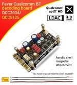
May I ask for help? And I really hope someone can help me. I have a bluetooth module (QCC5125).
First I programmed it to rename and set equalizer, it worked. Then I tried a second time, maybe I had the wrong program or whatever, and now my Bluetooth module can't be read on the cellphone, but it can still be read USB Port on the computer. Does anyone here have a dump file for this Bluetooth module?

Attachments

  • images (12).jpeg
    images (12).jpeg
    48.4 KB · Views: 54

Yet Another Soft Start Circuit

After looking at a bunch of soft start circuits I decided to design one according to my beliefs as to what is the best way to do it. It may be completely different from your beliefs but there it is.

I wanted a separate power supply for the soft start circuit so it could be used to turn the amp on and off and the powering up of the amps large transformer would not interact with the circuit. The transformer has a dual primary so it can be used for 115 and 230 VAC. There is a surge suppressor, R1, across the transformer input as well as a small high voltage capacitor to filter out RFI on the line from coming into the amp. The power supply always draws a few milliamps, it powers a multicolor LED that emits red with the amp in standby.

The on/off switch only switches 15 volts DC at very low current so you don’t need a switch that can handle large AC current in-rushes. When switched on, the DC power is sent through a regulator for consistent voltage and time of circuit operation. Relay K1, a small current relay, pulls in and turns on a triac, AC current flows through a couple thermistors in series to limit in-rush current, two 5 Ohm parts for 115 volts to limit the current to no more than 12 amps, or two 10 Ohm parts for 230 volts also limiting to 12 amps. There is a current limiting resistor, R2, at the triac gate and a RC network,R3/C2, over the triac for some protection of the triac.

The circuit uses a voltage comparator, U2, to delay turn on of a relay, K2, which bypasses the thermistors, I do not like to have a current limiter staying in the circuit or the heat they generate inside the amp. The voltage comparator has a voltage divider, R8/R9, to set the voltage at 10v as the reference voltage on the positive input. That voltage is compared to the negative input which has an adjustable resistor, R7, which limits the current charging the capacitor, C6, and the rate of charge therefore voltage ramps up quickly, a couple seconds to more than 10 seconds, for the delay. When the voltage on the negative input matches the positive input, the output is turned on. There is a diode, D4, across R7 to give a quick discharge path for C6 so the circuit can reactivate quickly, as in the case of a temporary power loss. R2 limits the current through the comparator which drives the gate of a small MOSFET through a gate resistor, R11. The MOSFET pulls current through a large relay K2 to bypass the thermistors and another small relay, K3, which changes the LED from red to blue to show status ON. There is a Zener diode, D5 and a small capacitor,C7, at the gate of the MOSFET to protect and stabilize it, probably not needed but cheap insurance.


So far, the circuit has been very reliable in a couple power amps with 2400VA and 4000VA toroid transformers with .78 farads to 1.2 farads of storage caps. In small part quantities the soft start board costs around $34 USD.
Attached is the Schematic, BOM and Gerbers. Enjoy.

Attachments

For Sale Oppo UDP-203 Upgrade kit - 2CH version, ES9038DAC chip

FS Upgrade DAC kit for the Oppo UDP-203 Player, This kit includes a new Audio Dac board -2 CH version, specifically designed to replaced the original Oppo Audio Dac section with ES9038 DAC, with new Firmware.Includes the PCB, custom firmware controller and all the parts, schematics, detailled BOM, etc.

This project was developed by one of the forum member, and the PCB/controller/Dac was sold some years ago. This kit is complete, and 100% compatible with the Oppo, just assemble, and replace the original DAC board.

These mods are still offered by: https://www.oppomod.com/, cost near 1K$...

NOTE: this is the 2CH version of this upgrade, meaning your Oppo player will have only 2Ch audio outputs after the upgrade!

See also my Oppo 203 Power supply upgrade board, all assembled and tested. original cost 280U$ (357$CAN once shipped to me...)

Asking 200U$ + shipping + Paypal 3.5% (Original price was 500U$!)

Attachments

  • 20250109_130610.jpg
    20250109_130610.jpg
    450.9 KB · Views: 59
  • 20250109_130616.jpg
    20250109_130616.jpg
    531.6 KB · Views: 58

NAD 521 with "audio modification"... worth buying?

Hello everyone,
I need a bit of advice. I have the opportunity to buy a NAD 521, which was revised and got an "audio modification" in 2015. The seller asks for €75, with p&p I will end up at around €85 (roughly $90). Its unclear what this "audio modification" means, the seller does not know. I attached a picture from the PCB. The Display looks rather dim on the pictures the seller provided.
Is it worth it? Ist the price okay? The device itself looks very clean and without any damage. I know there are quite some versions of the 521 around, with the plain 521 being the oldest. Should I look for a 521 BEE, which will be around €200 in my area?
I am looking for an affordable, good looking "vintage" CD Player with robust mechanics which can be upgraded with better components. The motivation to do this is more to learn a bit and just for the fun of modding. I do not expect to create something real high-end.
Cheers, Robert
Bildschirmfoto 2025-01-06 um 14.09.46.png

Hi from a new DIYer

I'd rather build than buy. I'm currently working on an SP-14 preamp from Vacuum Tube Audio and a Gainclone. After those are finished my signal path will be entirely home built other than the SL1200 (which is not without mods). I'm looking forward to seeing what everyone else is working on.

Here's a dual mono Emerald phono preamp from RJM audio that I recently built. The chassis were old serial KVM switches with some figured maple to add some flare.

20250108_164516.jpg


20250108_164601.jpg
Projects by fanatics, for fanatics
Get answers and advice for everyone wanting to learn the art of audio.
Join the Community
507,758
Members
7,887,170
Messages

Filter

Forum Statistics

Threads
406,169
Messages
7,887,170
Members
507,758
Latest member
Cindy