So I've found myself elbow deep in rebuilding this old arc vt60 amp for fun, and as an opportunity to learn more about tubes and how all this stuff works, so I appreciate commentary.
So this amp uses a single bias trimmer for each pair of output tubes. I would like to add individual adjustment, among other things. I've managed to find a few different ideas, and I'm hoping someone can set me on the right track.
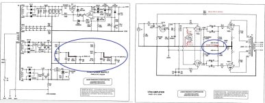
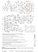
1.) Duplicate the bias adjustment circuit, and break the connection between R15 and R16, eliminate R18, add two new 1r resistors between each cathode and ground. (Blue circles on schematic)
2.) Add some cathode adjustment, like they did in the vt65/clone amp, 5r6 with a 100r trimmer. (Orange circle on vt65 schematic)
3.) Order and play with something more esoteric, like an AB-Qi module.
What say you, wise experts?
So this amp uses a single bias trimmer for each pair of output tubes. I would like to add individual adjustment, among other things. I've managed to find a few different ideas, and I'm hoping someone can set me on the right track.
1.) Duplicate the bias adjustment circuit, and break the connection between R15 and R16, eliminate R18, add two new 1r resistors between each cathode and ground. (Blue circles on schematic)
2.) Add some cathode adjustment, like they did in the vt65/clone amp, 5r6 with a 100r trimmer. (Orange circle on vt65 schematic)
3.) Order and play with something more esoteric, like an AB-Qi module.
What say you, wise experts?
Attachments

It's already not stock, the proceeds I would get for it at this point (if I was honest on the ebay listing) wouldn't cover anything worth having.move it along to someone who is looking for a stock ARC amp
I'm a tinkerer by nature, and half of the fun I anticipated having with this amplifier was in messing with it. As far as "friendly" stuff, I've got a bunch of that too, firstwatt amps, other repaired tube amps, tube buffers, etc. I'm a hacky/tinker type. Forgive me, but I think I'll keep it and make it my own. 🙂
I might suggest something similar to option 1 but implemented as a bias/balance circuit arranged such that if the wiper of the pot fails open than the tubes gets full negative bias voltage for a fail safe feature. An individual bias circuit is shown on the Valve Wizard page and shows how to make it failsafe.
http://www.valvewizard.co.uk/bias.html
I have used the auto bias boards like the ABQ and they work fine but you'd have to mount it somewhere and that might be difficult.
http://www.valvewizard.co.uk/bias.html
I have used the auto bias boards like the ABQ and they work fine but you'd have to mount it somewhere and that might be difficult.
nerdorama's suggestion of the Valve Wizard mod is worthwhile. I've seen tubes damaged by an open wiper on a bias pot.
Individual bias is no guarantee that the tubes behave similar. Only correctly matched tubes will and then you don't need the complexity.
If I were the OP, I would learn to use LT Spice.😉
I think that nowadays, taking advantage of the power of computing is invaluable, the program will do the calculations for you, and you will see the results without fear of damaging anything. Something similar to the acoustic cabinet design programs, but applied to electronic circuits.
I have not read the entire link that I attached, I think that LT Spice works for tubes too, not just solid state.
https://en.wikipedia.org/wiki/LTspice
I do need to do that, lol. There's a lot of things I've been meaning to dig into. I have it installed. Just need to buckle down and do it.If I were the OP, I would learn to use LT Spice.
I'll give that a read, thank you! The wiper coming off the pot and turning the tubes into lava was something that made me a bit nervous, too.I might suggest something similar to option 1 but implemented as a bias/balance circuit arranged such that if the wiper of the pot fails open than the tubes gets full negative bias voltage for a fail safe feature. An individual bias circuit is shown on the Valve Wizard page and shows how to make it failsafe.
The bottom cover is perforated, so mounting a few standoffs would be fairly easy, and there's a decent amount of space under the board where some tricks could hide.I have used the auto bias boards like the ABQ and they work fine but you'd have to mount it somewhere and that might be difficult.
Edit: The valve wizard page, it would seem that all I would really need to do is add a resistor across the adjustment pot.
If you go the AB-Q route you may need a higher bias supply voltage since you get some loss in the board and the slow start function wants a higher negative supply to keep the tubes closer to cutoff for the warmup period. Changing the bias supply to a voltage doubler might be an option.
It adds a bit of computational complexity. Since the VR can be any value in parallel with the fixed resistor, you don't know what the actual cathode resistance is for the calculation with the voltage until you turn off the amp and read the resistance. So just setting the voltage to a fixed value will not give you the cathode current. It's trial and error with multiple calculations.
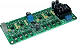
I have exactly what you need. Connected with another member and got these boards made to do exactly what you are looking for. I have blank boards extras and will send one if you want to try it.

I was wondering about the added math and not knowing the resistance in use until it's already set. I considered adding yet another resistor in series to serve as the test point, but now the bodges are getting crowded. 😛It adds a bit of computational complexity. Since the VR can be any value in parallel with the fixed resistor, you don't know what the actual cathode resistance is for the calculation with the voltage until you turn off the amp and read the resistance. So just setting the voltage to a fixed value will not give you the cathode current. It's trial and error with multiple calculations.
Oh, neat, yeah I'd love to take a look at one, that could work well. I'll send you a PM.I have exactly what you need. Connected with another member and got these boards made to do exactly what you are looking for. I have blank boards extras and will send one if you want to try it.
Funny, I bought one of those last week from e-bay. Looks pretty solid.
- Home
- Amplifiers
- Tubes / Valves
- Switching to individual tube bias - A couple of basic questions.