Hello all,
I've been trying to find a suitable driver for use with my Alan Eaton 45 SET amp, and have been all around the world for several weeks, first trying to go the fullrange route, ordering a pair of Liisong's new PT-10 drivers. I cancelled that order when I discovered the Radian series of coax drivers, and settled on the 5210, a 10" cone with a 1" aluminum alloy compression driver. Here is the page for it:
https://cdn.shopify.com/s/files/1/0111/0324/0254/files/5210C.pdf?v=1617035289</ul>
I decided to go with the Radian because of the success some people have had with them, particularly Frank Fazzalari of Coherent Audio. His speakers win high praise and not from the usual commercial circuit. There's also a company in Germany making beautiful speakers with these same drivers.
So. I've got lots of experience building and DIY'ing including amp mod stuff, but this is my first foray into a from-scratch design/build. I think I'm in the ballpark but "the more I learn, the less I know" has never been more true. Night after night I read until it makes no sense anymore. Recently read Martin King's work on MLTL/QW theory, and learned a lot although the math was about 40 years late for me. I'm needing assistance in two areas, the crossover and the boxes.
For the boxes, I've got a pretty simple idea for a BR enclosure, 2.2cu.ft/62l, or, if I can find a way to design it, a 3.3cu.ft/93l. Both of these were generated with free online software and compared to existing enclosures. I also got a version using Eminence software through US Speaker, where I purchased the drivers.
First - I don't know whether this driver is more at home in the TQWT or the BR, but I feel that a QW pipe with a full terminus would be a better choice. I don't know all the correct terms, so by 'full terminus' I mean where the throat opening is not restricted and is a continuation of the pipe cross section as in true Voigt pipes. I'd prefer the throat to be bottom front rather than an open base, as in Troels Graveson's designs. Try as I might, I cannot find a reliable resource to design this box, and would really appreciate some help. I will even pay someone to generate the design, as I'm way behind on my work and getting behinder all the time right now. But first I'd like to know if a simple bass reflex might be as good or better, though I doubt it. I prefer the bass response of the horn, not driving a narrow band slug at the terminus then falling away.
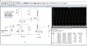
Second - the crossovers! I've plugged the T/S numbers in every free software I can find, and the a friend and coconspirator who has a Windows rig used Jeff Bagby's crossover designer as well, and I think I'm in the general ballpark but still not sure. I will post the FR of the drivers below, as well as the tweeter response with 5uF, 10uF, and 15uF caps on the tweeter (first order). Here are my questions about the crossover:
1. Frank declined to sell me his crossovers, and wouldn't give me the values, but we had a great conversation anyway, very good guy. Although he uses first order on both drivers, he said I might want to go second order on the tweeter. I would rather avoid an inductor on the tweeter mostly due to phase concerns, which is really high on my list and part of the reason I was originally going to use full-rangers. So first gate: first or second order?
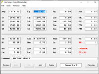
2. With first order Butterworth, I've got pretty typical values at 1200hz, 1350hz, and 1500hz: 16.56uF/1.06mH(woofer), 14.72uF/.94mH, and 13.25uF/.85mH. Second order on the tweeter only lowers the cap values a bit and adds a small inductor.
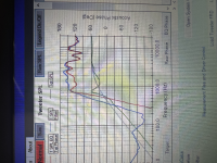
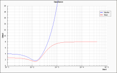
As you will see in the frequency/impedance graph for these drivers, there's a really knotty issue due to a sharp impedance spike from the tweeter at just below 800hz, and this is really interfering with the falloff of the tweeeter and pushing up the FR almost all the way to the intended xover point (I'm using 1350 as a general target). I don't know how to remedy this, and am beyond reluctant to even go to 2nd order, let alone 4th. I'd rather start from scratch with a different driver, BUT this doesn't seem to bother Frank, he's got some way of dealing with the impedance that I don't understand. Zu audio is another example of a popular speaker using cheap Eminence drivers and squeezing out very good performance. I'm guessing these guys are manipulating the enclosures to make it all work?
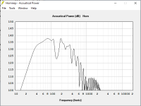
Below I will post the following: The Radian EQ/Imp graph, and the tweeter response for first order using 4.7, 10, and 15uF values plugged into Jeff's program. Any and all guidance is much appreciated, and like I said earlier I'm willing to pay to learn here, I wish I had a mentor in my area but there is nobody doing this. Cheers, Bryan
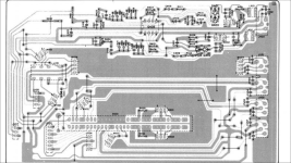
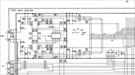
I APOLOGIZE FOR THE LAST TWO IMAGES BEING ROTATED, I DON'T KNOW WHY THEY LOADED THAT WAY!
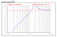
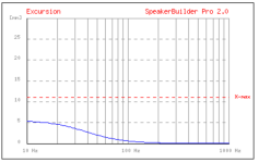
With 4.7uF cap, lower green line:
With 10uF cap:
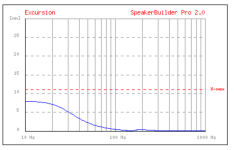
15uF:
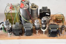
 20221028_120637.jpg540.5 KB · Views: 95
 20221028_120641.jpg654.2 KB · Views: 89
 20221028_120646.jpg672.2 KB · Views: 109
 20221028_120648.jpg808.6 KB · Views: 94
 20221028_120705.jpg724.7 KB · Views: 85
 20221028_120716.jpg666.7 KB · Views: 90
 20221028_120721.jpg647.9 KB · Views: 86
 20221027_092503.jpg899 KB · Views: 86
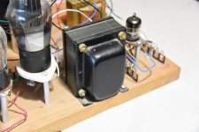
 20221027_092507.jpg883.1 KB · Views: 82
 20221027_092519.jpg762.8 KB · Views: 82
 20221027_092534.jpg823.8 KB · Views: 89
 20221027_092539.jpg765.4 KB · Views: 98
 20221027_092542.jpg859.5 KB · Views: 87
 20221027_100333.jpg868.1 KB · Views: 76
 20221027_100338.jpg899.9 KB · Views: 92
 20221027_100347.jpg844.5 KB · Views: 90
 20221027_100351.jpg864.8 KB · Views: 91
 20221027_100609.jpg825.4 KB · Views: 94
 20221027_100616.jpg841.3 KB · Views: 85
 20221027_100627.jpg840 KB · Views: 103
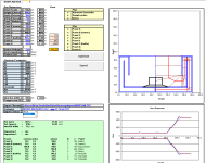
 Copyrighted material removed.