Need help with Linn Valhalla repair

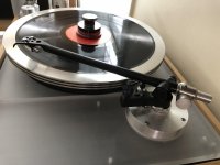
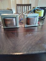
I've got a LP12 (somewhere 1985 model) that stopped turning.

All symptoms are similar to the ones as described in this old post (copy form the audio asylum):

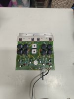
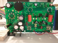
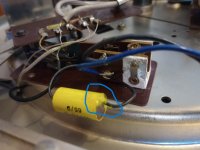
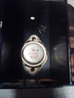
Yes, there are two items which experience failures that you can service yourself and fairly easily. Does the led in the switch light up? If so then the following is most likely the problem and it will just leave the motor vibrating or turning verrrry slowly. With the table plugged into the mains VERY CAREFULLY (enough voltage in there to end you listening career) measure the output to the motor between the red and blue wires, it should be between ~85 to 90+vts a/c (as I recall), depending on if you have the zener diode update. The large P/S caps will fail over time, just measure the each of the two them across the board for 160vts, if less they need to be replaced. The other field readily field serviceable failure will require a Valhalla repair kit from Linn which consists of the necessary parts. I don't remember the price. This failure is noted by blown fuses and a related triac and resistor. Hope this helps.

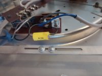
So I followed the instructions to repair it and replaced the capcitors with new ones. But the problem remainded the same.
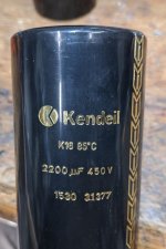
The voltages were 139VTS with the old capacitors and 140 with the new, os hardly any difference. This was in line with the output voltage on the rectifier which was 280V (SHouldn't that be 311??)

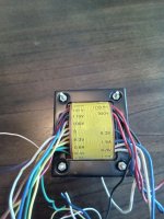
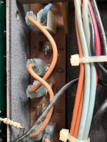
Output voltage on blue connection was 35V/50HZ and on the red 28V/50HZ

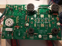
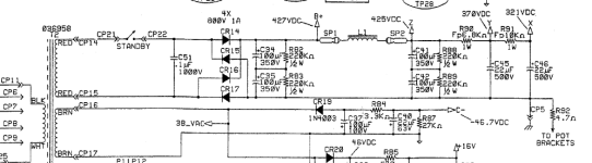
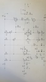
I found the schematics of this board and have attached them. I also tried to figure out how it works, but I'm to electronically ignorant to understand this so I was hoping to get some help over here. The schematics say: RV1 to be set to 85V+/- 1V. But when I measure that I only find 6 volts or so so this might indicate what is wrong.

Does anybody have some suggestions how to proceed?

Attachments

For Sale Rega RB250 with mods

Its come to my attention that I may have too many tonearms... I think its 6 now...maybe 7.

Anyway, even having a few other turntable projects in the future it seems that perhaps I’ve had my fun with this tonearm.

It has been rewired with the Incognito wire kit. It also has the Mitchell techno weight and adjustable VTA base collar.

I also have the original weight and stub for it in my storage closet somewhere.

The Clearaudio Rosewood Virtuoso is not included in the sale.

I poked around on the web looking for a pricing guideline...they seem to vary based on condition and mods.

I would say this arm is in good condition. Normal light wear from mounting of cartridge in screw slots. It works as it should.

The only other thing I ever noticed was some flaking of the gold plating on the plug where the wires enter the bottom of the bearing housing. I couldn’t get a pic as it is currently still mounted on my turntable.

I’m asking $375 for it. Additional cost for shipping and fees would be the buyers responsibility.

Attachments

  • DF3A5058-4E61-407C-9379-A67C9D5BFA07.jpg
    DF3A5058-4E61-407C-9379-A67C9D5BFA07.jpg
    566 KB · Views: 474
  • 3522CC3E-3455-4A8D-8054-29C69E55AB4C.jpg
    3522CC3E-3455-4A8D-8054-29C69E55AB4C.jpg
    665.3 KB · Views: 475
  • F9E6B5DB-182C-43F7-9C57-806B48AFAC1F.jpg
    F9E6B5DB-182C-43F7-9C57-806B48AFAC1F.jpg
    663.6 KB · Views: 479

Beginner trying to design a hybrid tape head playback amp

While looking for a tube playback amp for reel to reel tape machines and reading some of the threads from here I couldn`t find any schematic to try.
After studying different schematics for playback (Ampex 351, Studer C37 and my Fostex E2), simulating and learning from them, I came up with a hybrid design ala Allen Wright.

Gain is around 57dB and can be adjusted by changing value of resistor R3.
R2 and C3 values are suited for my Fostex E2 tape head (taken from service manual schematic)
EQ can be adjusted using R7 and output level using R13/18.
EQ was calculated for CCIR 15ips.
Added a mosfet source follower to lower the output impedance.

I did some simulations in LTSpice and the figures looks pretty good.

Let me know what you think. Attached some photos and simulation file.

FYI this is my first attempt to design a circuit, I`m no EE, I`m just a self taught diyer.
schematic.jpg
EQ.jpg
THD.jpg
Layout.jpg
View attachment TAPE REPRO HYBRID.asc

Any resistive opto isolators with a higher cell voltage?

Hello,

Has anyone ever come across a series of resistive opto isolators that can handle higher cell voltages than the popular types such as the Xvive VTL5 line and the NSL photo type opto isolators? I see most of these have a max cell voltage of about 60 volts and max power of about 50mW.

Reason I ask is that I'm implimenting some switchable mods on 12ax7 cathodes. All is well with the aforementioned opto's until I get to the cathode follower, at which point we are seeing voltages around 160volts.

It would be nice to have a means of switching in various bypass caps and resistors in parallel with the cathode resistors on the cathode follower sections.

Thank you!
Best,
Phil D

Designing a preamplifier for 3-head tape recorders: Levels and gain

Hello dear forum members,

I'm a designing a commercial preamplifier with tape recorder support. It will contain:
  • dedicated tape input,
  • dedicated tape output,
  • "monitor" switch allowing to route main output signal from tape input to the tape output
The monitor switch purpose is to listen for what is being recorded, if a tape recorder is equipped with a separate playback head. The goal is to make this switch operating correctly, without level and volume jumps when used. My dummy idea of making it of a gain of 1 resulted in a volume mismatch. There is also another consideration that the input level could be overdriven, because of high level, so the record level control knob won't be operating properly.

So my question is mostly about the tape recorder input level and gain which will be applied to the signal before the output. Is there any right assumption? Perhaps any standard on what a recorder should do to the levels on the input and outputs?

Quick investigation shows that my Revox B77 is applying about 32.3 dB of amplification, when input level knobs are fully open, meaning its input is expecting about 18.8 mV for its nominal output of 0.775 dBu. Having signals of tens of millivolts is rather weird, when most of the todays consumer equipment is having output levels of volts.

PS: My internal preamp nominal level is 150mV.

Will appreciate your suggestions, and feel free to suggest the right forum category.

UPDATE: Correction: the B77 nominal output is 0.775 Vrms, 0 dBu, not 0.775 dBu.

We crave for distortion :) - Generic amp for whole KT88-KT150 line

Dear all,

inspired by this forum post from ASR, I decided to prepare for my next project in advance.. and build something distorting next year. 😉

No, not a guitar amp, I mean I'd like to stay at HiFi quality but rather aiming for insanely low THD, I'd be happy to build a more triode-close amplifier, preferably with 0 feedback (or at least adjustable between 0 and full) and don't care of measurements. If it sounds sweet and great to my ears, my goal is achieved.

Efficiency is no aim either.

I have right now
  • 2x NOS JJ KT88
  • 2x NOS JJ E88CC
  • 2x NOS JJ ECC99

I can have power and output transformers wound in exceptional quality, not begun yet. Trying to estimate load (with KT-150 in mind).

Are there any good, reliable KT88 designs out there you are aware of which could be sized/extended with very minor modifications (maybe 1-2 switches, etc) to accomodate KT120s and KT150s too ?
I'm also a fan of microcontrollers so mechanical (or even solid state) relays are not an issue to use (if they don't degrade signal in the intended application and I can double them if needed for safety).
But if circuit design allows with very minimal modification I could live with that hard-wired option too. A switch (or bypass or any kind of quickly adjustable thing) on the amp's outside itself would be more convenient of course.

I'd really like to build 2 very simple Class-A monoblocks, tubes in triode mode with aforementioned tubes first, designed so that these amps could later also be happy with the heaviest KT-150 guys.
Just out of pure fun and learning - and wasting not only heat but time too. 😊

Any tips, ideas ?

300b with single stage driver, C3M or?

Howdy everyone, as it usually happens in the life of the diy enthusiast I have came upon the quest of the 300b. Upon much reading and research I have opted to seek out a single driver design, be it a la we91a and driven by a pentode or maybe a different topography with a suitable triode.
What do you guys think? I was nearly ready to order all the parts necessary for Thorsten's legacy using c3m driver but before I pull the trigger I was wondering if there was any other design I should take into account. My only criteria is that its a single stage driver design. Please advise.

D.

Preamp output MOSFETs

Hey DIYA
Is there any MOSFET's in production today in TO220 packed that is particular popular as outputs in a preamp?

My knowledge of these is quite limited, but might try to design my own preamp in the near future.
My preamp now is Acurus LS11 modded to a state where I need to move forward towards something else. I found much inspiration from the Aragon lineup (28K and Aurum for example) with their enhanced MOSFET.

Regards

Laney LX120RTWIN

Hi,

This amp had its bridge rectifier and darlington power transistor STD03P blown. This transistor is obsolete. I have 3 pairs of SAP16P transistors and heard that they can be used as substitutes. As per datasheet, the STD03P does not have an inbuilt emitter resistor whereas the SAP16P has the inbuilt resistor. So If I replace it with the SAP16P, then, do I have to remove R14 and R21 from the circuit. Schematic attached, Please assist.

Thanks

Attachments

Replacement tweeter power rating

Hey all. I am trying to select a replacement tweeter compression driver to be suitable for use with my existing 2-way crossover and woofer. I will be adding an L-pad (or resistor network) to match sensitivities.

My crossover is 2.5KHz @ 12 db/oct and my woofer is 15" rated at 150W and about 98 db 1W/m. I've heard of a rule of thumb that the power rating of the tweeter should be about 1/5 of that of the woofer. So this would suggest a 30W tweeter.

Most compression drivers I've been looking at are about 107 db 1W/m, so in order to equalize the sensitivities the L-pad will consume a larger portion of the system power. I gather -10 db is 1/2 of the power.

For a pair of speakers there is considerable difference in price between a 30+ watt tweeter and, say a 15W or 20W tweeter. Question: can I safely use a lower powered tweeter in this application? What are your thoughts?

Thanks in advance.
R

Best opamp for I/V conversion? (DAC)

Hi,

I am quite sure this has been discussed before but I did not find it using the search function.

I am going to bulid a DAC using CS8420, DF1704/06 and 2xPCM1704; followed by opamp for I/V conversion, passive HF filter and another opamp as output buffer.

The output buffer will be Analog Devices AD8610, but I am not sure which one would be best for I/V conversion. Maybe AD8065? Any suggestions are welcome.

Cheers
Christian.

Replacing complicated "Darlington Pair" circuit into one Darlington Transistor

Hello everyone.

I'm building a capacitance multiplier PSU based on this article.
(for who can't link to site : https://sound-au.com/project15.htm)

Looking at the Figure 3 - Complete Dual Capacitance Multiplier (Darlington Pair) schematic, there are 2 transistors and 1 diode per supply rail to make up "darlington pair" topology.
1697409128932.png

At first, I've tried to build a pcb following above schematic, but soon I realized there are no much space to place those transistors and the distance of transistor's heat sink and caps are too short.
So I gooogled it to find solution and I noticed about the "Darlington Transistors".

After while then, I found npn and pnp darlington transistors, manufactured by on semiconductor, looks okay to replace transistors above schematic.
The MJH6284G and MJH6287G. (here's the datasheet : https://www.mouser.kr/datasheet/2/308/1/MJH6284_D-2315692.pdf)

( also the datasheets of TIP35C and BD139G's
TIP35C : https://www.mouser.kr/datasheet/2/389/tip35c-1852460.pdf
BD139G : https://www.mouser.kr/datasheet/2/308/1/BD135_D-2310428.pdf )

According to the datasheet, The maximum dc current gain of 6284G is greater than the gains of tip35c*bd139.
Also the VCEO max and VCBO, VEBO value of TIP35C and MJH6284G are same, gain bandwidth of 6284G is larger than TIP35C's.
Most of the electrical characteristic of 6284G are same or better than the TIP35C, so can it be a replacement of "darlington pair" parts?
p15_fig3 (1).gif


One thing I concern about is Continuous Collector Current. The TIP35C's is 25A, while the 6284G's is 20A.
Would the max current of transistor degrade performance of power supply?

The power requirements in my case is maximum 18V 2A per rail, so supplying that power seems not problem.
But I wonder lower collector current could be lead to higher ripple noise.

Giving me your opinion would be highly appreciated.
Thank you.

Standardizing crossover components values?

Hello

I'm new to passive crossovers. Forgive me if this is a dumb question.

I found the following old thread : https://www.diyaudio.com/community/...h-order-linkwitz-riley-2-way-at-3-khz.339215/

I am also trying to use a 4th order linkwitz riley crossover(in my case 2.5k), and I found the following values through a calculator.

C1=8.44 µF
C2=16.88 µF
L1=0.16 mH
L2=0.72 mH
C3=25.33 µF
C4=5.63 µF
L3=0.48 mH
L4=0.24 mH

However, I have no idea how to "standardize" them as the thread I found says.
(e.g. changing 8.44uF to 10uF)

As I understand it, the calculator multiplies cratio and lratio by a certain value, and it seems that increasing or decreasing these ratios by the same percentage will result in a completely different filter.
Can anyone tell me how to "standardize" specifically?

Did quite a research but couldn't find the answer 🙁

For Sale Wolverine EF3-3 Partially Assembled

SOLD - For sale a set of EF3-3 Wolverine PCBs partially assembled using parts as recommended in the BOM for a 100W build. Build guide revision 24 dated 08/09/2022 was used. These boards passed the first set of tests as outlined in the build guide. Only the output transistors and Q104 transistors left to be installed. Price $300, this is less than the cost of PCBs and parts.

I also have a Antek AN-5435, caps, bridge rectifiers and assembled Mark Johnson H9KPXG soft start board available that I was going to use for this build if interested. - SOLD

wolverine_1.jpg
wolverine_2.jpg

Internal bracing cubic volume offset?

Just wanted to know if I should be adding volume to offset bracing.? I’m hoping the answer is yes because I’ve somehow ended up with 2.4lt of additional volume lol.!
17.1 to 19.4, subsequently the internal height is now 20mm shorter and the internal depth is 40mm deeper..!!! I at least got the width correct..!! It’s a ported enclosure using Markaudio 10p

My question is, would the above shape changes have any impact? The original design was 369mm internal height so would I need to place the driver and port a little higher to compensate?

Thanks in advance, it’s my first build so hopefully someone can help..!! It’s not really an issue to cut more ply to the right size but I prefer the look of this cab being a tad shorter and deeper.

Cheers
🔫

3D-Printed Spherical Speakers

My roommate and I picked up some full-range 3” and 4” drivers at BAF23 raffle, with the intention of taking our very first foray into DIY speakers.
I had long put off building speakers on account of the dizzying amount of considerations, optimizations, and calculations one could leverage to design a (good) speaker.
My roommate assured me it’s well within our abilities to make a bad speaker, and perhaps we would learn something along the way—so no more excuses.

The result was a shootout between competing spherical designs (with a bonus fake “TL” concept speaker cab). Misprints aside, the results actually sounded surprisingly good to us. The biggest glow-up was the 3” driver, which really sounded far better then I gauged it would just off the unmounted listening test.

Attachments

  • IMG_2927.jpeg
    IMG_2927.jpeg
    518.8 KB · Views: 215
  • IMG_2926.jpeg
    IMG_2926.jpeg
    590.2 KB · Views: 216
  • IMG_2924.jpeg
    IMG_2924.jpeg
    529.9 KB · Views: 200
  • IMG_2908.jpeg
    IMG_2908.jpeg
    477.8 KB · Views: 215
  • IMG_2902.jpeg
    IMG_2902.jpeg
    471 KB · Views: 196

Direct coupled amplifier problem

Dear diyaudio members
It´s been a few weeks i try to repair one audio amplifier. Special one for me, because of these keywords: cascoded current mirrors, fully symmetrical design, direct coupled with DC-servo. Voltage feedback is taken from the "darlington driver" stage which drives the IGBTs and for zero DC output is responsible the only not discrete component on the board - the OP07.
The main problem was "invisible" but while checking with the scope I found the problem in defective via in PCB under one of the main caps pins. This cap filtered the -56V rail. The result was overloaded power stage. This was audible while turning on the machine. The logic board watched this status carefully and immediately disconnected this faulty channel off. After this procedure I powered the amp again but another issue appeared. Voltages on gates of power IGBT´s are not symmetric for N and P and also it is impossible to set any quiescent current thru output transistors. The "thermal sensing" BD139 which is responsible for idle current setting doesn´t allow to open them.
I already soldered out these nice Toshiba IGBTs and measured gate treshold voltages and these sits around 2,5V.
The problem is that whole output from the input module is DC shifted and I could not find any way to set this correctly.
The input module was small PCB completely sealed in plastic enclosure with 10pin board to board connector. In the schematic this module is highlited as INPUT MODULE. The manufacturer of this amp wasn´t much helpful so I made some cruel reverse engineering and redrawn the full schematic of power amplifier board.

1: repaired faulty via in PCB
2: checked output transistors and I also measured them on curvetracer
3: checked OP07, it was good, but replaced with new one
4: found some BC550/560´s with very low beta(can´t remember which exactly)
5: paired and combined the transistors to match positive/negative 15 and 16V rails
6: paired transistors in outer current mirrors which are biasing the input transistors inside input module
7: the same was done for inner cascoded current mirrors

Pairing was in a sense of chooding the Vbe, h21e and reverse biased EB breakdown. I played with everything at this board but there is still assymetry on input module outputs..I gave up and posted this thread. Any advices ladies and gentlemen?

Attachments

  • full.jpg
    full.jpg
    186.2 KB · Views: 457

Solartron 43A216154P2 transistor info needed

Hi guys,
Would any of you have info about the solartron transistor 43A216154P2 ?
I have about a dozen of those and would like to put them to some use.
They are 1/2" stud mounted quite big transistors, propable high voltage switching transistors.
All i could find by searching the web was that they are obsolete aviation parts.
I really would appreciate if any of you could give me some info about them.
Thanck you

SE to Balanced cable - the correct way

There are many discussions on this topic but I am not clear as to which is the correct way of making a SE to Balanced cable. Using two-conductor + shield cable. SE source to Balanced input amp.

It basically boils down to two topologies:

1. Hypex recommends connecting the shield at the SE end;

2. RANE recommends leaving the shield (at the SE end) open.

Which is correct? Is there a difference?

Attachments

  • hypex SE-Bal.png
    hypex SE-Bal.png
    12.9 KB · Views: 244
  • RANE SE-Bal.png
    RANE SE-Bal.png
    10.9 KB · Views: 286

How Many Folds is Too Many

Hi Folks,

I am presently designing a 10 inch back loaded horn for bass guitar use. The outside dimensions are somewhat fixed by the amplifier that needs to sit on top, and the size of my car.

The current iteration of the design, which is simulating nicely in Hornresp has four 180 degree bends and two 90 degree bends.

What problems might I find with such a folding (if any), and are their ways to mitigate them? If the only consequence is the horn signing off a little lower than it would if it were a straight horn, that is not undesirable at all.

Where should reflectors be placed, ideally?


Screenshot 2023-10-03 193914.png

need help: low latency wireless audio transmission for guitar?

Hello! for a guitar effect device we want a setup like this: ADC->(I2S)->MCU (audio processing, simple) -> wireless -> MCU-> (I2S)->DAC Amp.
We need mono, 16bit, 32khz or better, with low latency ( <10mecs). We tried to achieve this with a pair of ESP32 with audio codec chips connected via I2S.
We used the proprietary ESP-NOW protocol, but with no luck, the latency that can be achieved is too high and the wireless protocol doesnt work well in environments with a lot of traffic in the 2.4ghz band (routers, phones, BT etc.).
However, there are affordable guitar tranceiver pairs which can do just that ( low latency, high quality mono audio) without problems. But i cant see the hardware that used, they scraped off the labels from the chips...
There is a simple audio tranceiver module pair available (from China), which uses the nrf24L01 chip, in conjunction with a ATMEL MEGA48 processor (very low spec 8bit) and Wolfson ADC and DAC chips.
And they work just great! How is this even possible? the MEGA48 doesnt even have a I2S interface. the latency is very low and the audio is 16bit with a sample rate >=32khz.
I need advice or even support on how to achieve this, so we can use it in our guitar effect. Can you help ? Any ideas are appreciated,
Cheers!

DIY tube cages

Anyone make their own cage or “protective” cover?

I have been looking at a couple of circuits using top cap tubes like the 807, but having pets and such would like to have the plate cap inaccessible to some degree. Most the circuits I’ve been expiring are SE, so some sort of cover for just the output tube would be nice.

One I’ve seen is the one Pete Millet did. He used a borosilicate glass tube with a machined vent cover which is very slick. I didn’t know how well it would do for heat dissipation though.
http://www.pmillett.com/PL177.html

Let’s hear your ideas and especially see any cages and such you’ve made for inspiration please.
  • Like
Reactions: andyjevans

Midrange/Tweeter Hiss - Weird situation... can you explain this??

Hi, all....

I've recently installed a Sony XM-GS4 (4-channel, Class A/B amp), and I have some speaker hiss through my midrange and tweeters. It's not audible with music playing, but it's slightly audible from the listening position (driver's seat).

It's ABSOLUTELY the amp and nothing to do with my install. I bench-tested it with no signal and different speakers, and the hiss is always there. Trust me, I've troubleshot the CRAP out of this one, and I'm 100% sure it's just what the amp does.

Here's what's weird, though: After listening to music on the amp for a while (5-10 minutes), you can turn the volume all the way down, and this hiss is usually (but not ALWAYS) completely gone... dead silent on all speakers. Turn the car (amp) off and back on... usually the hiss is there (but a couple of times it WASN'T there).

So, three questions, if I may:

(1) When would you consider speaker 'hiss' a problem or in need of address? I'd love a tomb-silent noise floor, but that might not be possible or realistic. I wonder if it's not that bad and I'm just being a crazy person at this point. lol

(2) Is there anything you can recommend to reduce that hiss (the gains are already all the way down on the amp)?

(3) ANY idea why the hiss might be there at start up but dissipate? I speculated that maybe the new components (it's a brand-new amp) like capacitors maybe needed time to 'break in,' but I've never heard of anything like that, and I can't find anything to support that theory.

I'd love any insights you might have to help save my sanity! Thanks, friends!

L15DSMD Digital power amplifier BY LJM

I designed it, using IRS2092 + IRFI4019H.
Piece element. Digital power amplifier.

USE + - 35 TO + - 55V DC


Frequency response diagram - actual measurement: (digital power amplifier, because of the relationship of the filter, will have a little upward gain measured in a 8 ohm load, which will not be shown in 4 Europe. This measurement data is consistent with the official IR)

Attachments

  • DSC_0006_??.JPG
    DSC_0006_??.JPG
    94.2 KB · Views: 1,190
  • DSC_0008_??.JPG
    DSC_0008_??.JPG
    125.9 KB · Views: 1,119
  • DSC_0009_??.JPG
    DSC_0009_??.JPG
    93.9 KB · Views: 1,226
  • 2jpg.jpg
    2jpg.jpg
    133 KB · Views: 1,185
  • THD+N.png
    THD+N.png
    74.2 KB · Views: 1,177
  • ??????.jpg
    ??????.jpg
    141.5 KB · Views: 720
  • ?? 8R.jpg
    ?? 8R.jpg
    175.3 KB · Views: 727

Tubes for sale

Sale:
1А2P – 390 pcs.
1B1P – 6 pcs.
1B2P – 3 pcs.
1J18B – 100 pcs.
1J24B – 23 pcs.
1J29B-R – 360 pcs.
1К1P – 2 pcs.
1P24B - 49 pcs.
1P24B-V - 34 pcs.
1P33S – 3 pcs.
1C21P – 1 pc.
1C7S – 1 pc.
1E1P - 5 pcs.
2D2S – 100 pcs.
2D3B – 2500 pcs.
2J27L – 1000 pcs.
2J27P – 81 pcs.
2К2М – 117 pcs.
2P1P – 116 pcs.
2P2P – 66 pcs.
2P29L – 109 pcs.
2P29P – 89 pcs.
2C2S - 126 pcs.
3C18P - 50 pcs.
3C22S - 40 pcs.
4D5S – 20 pcs.
4P1L - 367 pcs.
5C8C – 6 pcs.
5C9S – 2 pcs.
5C12P - 25 pcs.
6А2P – 62 pcs.
6А3P – 67 pcs.
6А4P – 21 pcs.
6А7 – 58 pcs.
6А8 – 503 pcs.
6V1P – 93 pcs.
6V2P – 67 pcs.
6VS-1 – 8 pcs.
6G2 – 55 pcs.
6G7 – 2 pcs.
6D3D – 30 pcs.
6D13D – 79 pcs.
6D14P – 23 pcs.
6D20P – 2 pcs.
6J1B – 32 pcs.
6J1B-V – 1468 pcs.
6J1J – 16 pcs.
6J1P – 6 pcs.
6J1P-ЕV – 66 pcs.
6J2B – 79 pcs.
6J2B-V – 144 pcs.
6J2P – 20 pcs.
6J2P-ЕV – 90 pcs.
6J3 – 151 pcs.
6J3P – 221 pcs.
6J3P-Е – 292 pcs.
6J4 – 303 pcs.
6J5B-V – 1312 pcs.
6J5P – 52 pcs.
6J7 – 16 pcs.
6J8 – 166 pcs.
6J9G-V – 31 pcs.
6J9P – 42 pcs.
6J9P-Е – 47 pcs.
6J10B-V – 689 pcs.
6J10P – 156 pcs.
6J11P-Е – 425 pcs.
6J20P – 169 pcs.
6J21P – 70 pcs.
6J22P – 68 pcs.
6J32B – 307 pcs.
6J33А-V – 50 pcs.
6J38P-ЕV – 500 pcs.
6J43P-Е – 257 pcs.
6J44P – 2 pcs.
6J49P-D – 41 pcs.
6J49P-DR – 90 pcs.
6J51P – 448 pcs.
6J52P – 46 pcs.
6I1P – 158 pcs.
6I1P-К – 1 pc.
6I1P-ЕV – 1 pc.
6I4P – 118 pcs.
6К3 – 182 pcs.
6К4 – 60 pcs.
6К4P – 14 pcs.
6К4P-ЕV – 26 pcs.
6К6А-V – 1 pc.
6К7 – 1 pc.
6К13P – 315 pcs.
6N3P – 145 pcs.
6N3P-Е – 870 pcs.
6N5P – 11 pcs.
6N7S – 394 pcs.
6N15P – 601 pcs.
6N16B-V – 61 pcs.
6N16B-VI – 175 pcs.
6N16B-VR – 23 pcs.
6N17B-V – 946 pcs.
6N18B – 26 pcs.
6N21B – 1 pc.
6N24P – 413 pcs.
6N27P – 14 pcs.
6N33B – 12 pcs.
6P1P – 8 pcs.
6P1P-ЕV - 282 pcs.
6P7S – 109 pcs.
6P9 - 80 pcs.
6P13S - 237 pcs.
6P15P - 95 pcs.
6P15P-ЕV - 14 pcs.
6P18P - 298 pcs.
6P21S - 31 pcs.
6P23P – 19 pcs.
6P25B – 1 pc.
6P25B-V – 15 pcs.
6P30B – 5 pcs.
6P30B-R – 18 pcs.
6P31S - 34 pcs.
6P36S - 50 pcs.
6P43P-Е - 180 pcs.
6P45S used - 31 pcs.
6R2P – 2 pcs.
6R3S-1 - 10 pcs.
6R4P - 18 pcs.
6S1J - 100 pcs.
6S2B - 16 pcs.
6S2B-V - 6 pcs.
6S2P – 82 pcs.
6S2S metal base - 1 pc.
6S3B-V - 2 pcs.
6S3P-Е - 62 pcs.
6S3P-ЕV - 57 pcs.
6S4P-Е - 1 pc.
6S4P-ЕV - 63 pcs.
6S5D - 63 pcs.
6S5D-I - 53 pcs.
6S5S – 45 pcs.
6S6B – 2 pcs.
6S6B-V – 16 pcs.
6S6B-I – 20 pcs.
6S7B-V – 5 pcs.
6S8S - 81 pcs.
6S9D - 34 pcs.
6S17К-V – 3 pcs.
6S19P – 11 pcs.
6S19P-V - 55 pcs.
6S20S – 3 pcs.
6S28B-V – 6 pcs.
6S29B-V – 6 pcs.
6S34А-V – 13 pcs.
6S46G-V – 19 pcs.
6S51N – 18 pcs.
6S51N-V – 15 pcs.
6S52N – 5 pcs.
6S52N-V – 23 pcs.
6S53N-V – 100 pcs.
6F1P - 123 pcs.
6F4P - 230 pcs.
6F5P – 101 pcs.
6F6М1 – 3 pcs.
6F6S – 1 pc.
6F12P – 77 pcs.
6H2P – 4 pcs.
6H2P-ЕV - 79 pcs.
6H2P-ЕV ОS - 51 pcs.
6H6S - 105 pcs.
6H7B-V - 105 pcs.
6C5S - 204 pcs.
6C19P - 20 pcs.
6E5P - 642 pcs.
6E5P-I - 41 pcs.
6E5P-DR - 26 pcs.
6E6P-Е - 15 pcs.
6E6P-DR – 30 pcs.
6E15P - 66 pcs.
6E12N - 9 pcs.
6E12N-V used - 37 pcs.
10J1L – 50 pcs.
12J1L – 136 pcs.
12S3S – 48 pcs.
13P1S – 2 pcs.
16F3P - 40 pcs.
30P1S – 1 pc.
EМ-7 – 32 pcs.

Pair of empty Tannoy T185 Dorset cabinets - Free for pickup or if you pay for shipping

FREE (giving them away)

I have a pair of empty Tannoy T185 Dorset cabinets. I'll give them away for free to anyone who wants them.

The cabs have mounting holes for two 10" drivers each, one 10" dual-concentric driver and one 10" passive radiator. They were not recessed/flush-mounted, they were front-mounted flat on the baffles. Easy to modify.

The cabs have walnut veneer, are in very good condition (vintage early 1980s).
The grilles are in good condition too, but the brown fabric has some wear. The frames are fine, no dents, cracks, etc. The grille cloth is rough, but presentable. They could certainly be covered with new grille cloth, if you're looking to do something like that.

I'm in SE NY State (USA). Free for local pickup. If you want shipping, it will be expensive because they're large, so that would mean two large cartons.
PM me if interested. Thanks.

How increase the max volume in a little speaker

First excuse me if my question is absurd, but I am trying a small diy project and I am not an expert in electronics and even less in audio, I have tried to learn how audio works but I am very dumb at it and I have more questions and in the end I don't understand anything.

I have an esp32 and it plays a small sound for 4 seconds.
I have tried with max98357a amp and pam8610 and pam8403 amp.
I have a 3w 4ohm speaker.

The idea is to get at least ~100db of sound and if possible at least in a radius of 5 meters but I can only get ~88db (tested with a mobile app).
I have tried to put amplifiers in series and in parallel, this last one I saw in a youtube video.

Sound distortion is not a problem, but I can't use a bigger speaker, I have a limited diameter, could I increase the height?
I saw some videos changing the capacitors in the pam8610 to improve the BASS but I'm not sure if this can help my problem.

Thanks in advance

Mackie Thump18s heating resistor on the output

Hey guys,

I’ve got a Mackie thump18s subwoofer amp module in for repair. The initial problem was the protection mode is engaged with no sound. Someone else was in before me and managed to fix the problem. But it failed on the first gig, same problem.

I had a look and it looks like components around and probably the IC NE556 (U5) were replaced.

To start with I was probing around that area too. After an hour of troubleshooting couldn’t find any obvious issue. During this time I was turning the amp on and off so it was not on the whole time. After a break, while I had the amp on I heard a very faint spark sort of noise (the sort of noise you might hear when a component burns and gives up) the amp came out of protection mode and the HV was turned on. I figured a shorted component which was causing the protection to turn on finally gave up. But as the HV was turned on, in couple of seconds I started to see smoke. Quickly turned off the amp.

The cause of the smoke was the glue on R174, and that resistor gets very hot the moment the HV is turned on. I probed that area and I measured ridiculous level of oscillation, I have attached a screenshot. I probed the same point on Channel 2 and it also did have a similar waveform but was very small in amplitude. I have two 8 ohm resistive dummy loads on each output, removing them cause the amplitude to go even high. I had to do all the measurements with in minute of the HV turning on as the R174 gets very hot.

Any idea what could be causing this? What should my next troubleshooting point be?

The amp is set at bridge mode and I noticed R175 was not populated on Channel 2.

On a second note, when the power is turned on, there is a time delay before the protection mode is off and the time varies each time. That is not the usual behaviour for these as far as I know, and I noticed when I probe with a multimeter the output of the NE556 which is on the measuring side for the current limit, protection turns on in a second and turns back off again. Happens every time when I touch the probe to the output pin. What could the reason for this be?

Attachments

  • Thump18 Output Schematic.png
    Thump18 Output Schematic.png
    61.2 KB · Views: 204
  • Thump 18.png
    Thump 18.png
    136.4 KB · Views: 168
  • Mackie_THUMP-18S Schematic.pdf
    Mackie_THUMP-18S Schematic.pdf
    378.4 KB · Views: 370

Analysing 500W BTL class D amplifier schematic

Hello,

seems I finally got another excuse to play with something interesting: Got a four of these rather old and very good active DSP bi-amped speakers, and after almost 20 years, the internet finally gave out the schematic for them. During some repairs in the recent years, I have reverse engineered the complete schematic of the HF amp. This time however, we can finally see the Italian beauty in its fullest, and finally I can get some understanding how they have designed the class D LF woofer amp. Please find the schematic attached.

The most relevant part of the class D design is at page 10 (modulator) and page 11 (power stage). At first, it did look intimidating, but most of the parts are rather simple and easy to understand, except one that is pictured below.

For others not familiar, to easier orient in the design, I made the following notes:

The input differential audio signal is fed into U5-A (gain is about 0,66) and low-pass filtered by U5-B (~100kHz cutoff). U1-A seems to be the main error amplifier and U1-D seems to be some form of a PI-controller* (see further). Transistors Q4, Q5 make a form of amplitude limiter to about +-2.56V (5.12Vpp, just assuming Vbe of 600mV). This control signal is then split into a buffered (U1-B) and negative (inverted by U1-C) portions. Further (negative only) amplitude limiting is applied to these by means of Q2 and Q3 to about no less than -2.48V (again, assuming 600mV Vbe). This pair of limited signals is fed to a pair of comparators, which produce a PWM signal by comparing with a triangle wave generated by U9-A. PWM signals are then again split into positive and inverted by using the OR and NAND gate (to make matched delays in both positive and inverted paths) and provided to the respective gate drivers (IR2110 on the page 11).

Feedback is provided to the U1-A and U1-D from an output of the power stage. A differential amplifier U4-A, U4-B senses the differential voltage across the load after the PWM is low-pass filtered.

The triangle wave is produced by an integration of a 50% square wave by U9-A. Square wave of 250 kHz is generated by dividing a 1MHz ceramic resonator oscillator by 4, using two T flip-flops. Feedback network R27, R28, C27 provides a stable DC operational point of the integrator, so the triangle is well centered across 0V at all times. The trimmer R53 can slightly tweak the integrator's time constant, so an exact amplitude on the output can be set. Mid-point position of the trim pot seems to provide almost exactly 5Vpp of triangle wave (at mentioned 250kHz).

The part of schematic i am not confident I understand enough, is this one around U1-A and U1-D.

PSR212a_err_amp_reg.png


It seems to me, U1-A is a kind-of normal non-inverting amplifier, setting the overall gain of the whole class D to be (1+R46/R43) = (1+47k/10k) = 5.7, multiplied by the gain of the diff-amp U4 (gain of the diff amp is about R34/R35 = 330k/35k = 9.43 or rather 1/9.43). The overall gain of the class D amp then should be 5.7*9.43 = 53.7x, not counting the input attenuation of the U5 differential amp. That sounds reasonable, however not true, see at the end.

U1-D seems to be a PI controller, with the DC gain set to R14/R11. What is however a bit strange to me is where the non-inverting input of U1-D (pin 12) is connected at: There is a voltage divider R12 R13, providing a portion of the feedback signal from U4. Is it some kind of a feed-forward?

My main question now is are all my assumptions right?
I think this must be some pretty standard class D modulator topology, however I was unable to find anything about it. I am only familiar with the single-ended Philips-patented self-oscillating thing (with feedback after LC filter) and the single-ended "IR audio amp" scheme using the self oscillating second-order integrator (feedback before LC filter). Do you know about any application notes or papers describing this topology and its design in detail?

My intention is to try to build a class D like this for some other application, hence trying to understand the design, so I could take some inspiration.

So far I have put in LTSpice the main part of the class D, and made it work. The simulation is also attached, for reference. What I have learned from the simulation, is that by removing the feed-forward path (R12, R13 divider or R24, R23 in simulation) from the controller ("PI regulator") opamp U1-D (U7 in simulation), the amplifier of course also works, but the step response of the amplifier gets much worse. Applying the feed-forward however influences the overall amplifier's gain and I am unable to figure out, how to calculate that one just from the resistor values.

Thank you for any suggestions or comments to help me understand how it works.

Regards,
Yan

Attachments

For Sale Hawk HB20

Two original and new HB20 hybrid amp modules from Hawk Audio
Comes with 2 transformers 2 x 25 Vac ( Amplimo ) for the power amp and one for the tube filament and name tag is included
Price 150 Euro a piece , shipping not included and + PP fee when sale is outside Europe
Using one for myself and I realy love it .

Attachments

  • Hawk BP 20.jpg
    Hawk BP 20.jpg
    357.1 KB · Views: 154

Choosing input capacitor

Hello I'm currently trying to complete the p3a amplifier, and trying to find a good input capacitor, I found 20 in my drawers and tested the on my oscilloscope, it has frequency response analysis, all are tested under same conditions and same load, 22k.
I'm having trouble interpreting the grafs, would appreciate some input, first time I've used this function.
Ps highest uf values first
20231014_163800.png
20231014_163514.png
20231014_163427.png
20231014_163340.png
20231014_163259.png
20231014_163220.png
20231014_163132.png
20231014_163045.png
20231014_162951.png
20231014_162905.png
20231014_162800.png
20231014_162700.png
20231014_162556.png
20231014_162507.png
20231014_162416.png
20231014_162326.png
20231014_162224.png
20231014_162122.png
20231014_162045.png
20231014_161857.png

2 NEW NOS -- KEF Passive Woofer Driver Radiator BD139 SP1042 PR -- NH USA

$99 shipped Northeast USA
add $10 if outside the northeast

Attachments

  • 20231014_143116.jpg
    20231014_143116.jpg
    452.7 KB · Views: 113
  • 20231014_143123.jpg
    20231014_143123.jpg
    446.3 KB · Views: 98
  • 20231014_143124.jpg
    20231014_143124.jpg
    444.1 KB · Views: 92
  • 20231014_143131.jpg
    20231014_143131.jpg
    583.9 KB · Views: 91
  • 20231014_143136.jpg
    20231014_143136.jpg
    533.8 KB · Views: 81
  • 20231014_143141.jpg
    20231014_143141.jpg
    464.6 KB · Views: 83
  • 20231014_143145.jpg
    20231014_143145.jpg
    444.8 KB · Views: 122

B1-Turbo on a Chip

..
..
A while ago, I published an article on alternative follower configurations :

http://www.diyaudio.com/forums/showthread.php?s=&threadid=128571&highlight=

I said alternative, because there have already been the famous Curl / Borbely followers, both in single-ended and the complementary versions. And they have been around for quite a while now. The recent revival of, and the vast interest in the B1-topology, which I find truly amazing, can only be described as a “Pass” phenomenon !!!

Also in my discrete opamp thread from last year, I commented that there could be better ways to do a DIP-8 unity gain buffer than using an opamp :

http://www.diyaudio.com/forums/showthread.php?postid=1480342#post1480342

i.e. a SMD-B1 on a 10mm x 10mm footprint, using a matched pair of BF862’s.

For Sale LaVoce SAN214.50 Sealed Subwoofer Hypex FA502 £1000

For sale is my DIY subwoofer. It contains LaVoce SAN214.50 driver powered by the Hypex FA502. The cabinet is 62x62x55cm (HWD) and weighs around 60kg. It is very heavily braced, with roundovers and painted using duratex. Price is £1000 NOT including shipping. I would prefer collection but I am open to the buyer sorting out a courier for this.

Note: the amplifier is unfortunately scratched on the rear, this in no way affects the performance and is purely cosmetic!

Attachments

  • IMG_9794.jpeg
    IMG_9794.jpeg
    401 KB · Views: 197
  • IMG_9795.jpeg
    IMG_9795.jpeg
    489.5 KB · Views: 184
  • IMG_9796.jpeg
    IMG_9796.jpeg
    306.4 KB · Views: 127
  • IMG_9798.jpeg
    IMG_9798.jpeg
    433 KB · Views: 141
  • IMG_9797.jpeg
    IMG_9797.jpeg
    679.9 KB · Views: 165
  • IMG_9918.jpeg
    IMG_9918.jpeg
    461.6 KB · Views: 149

TI Spice Files

I was trying to see if there was a spice model for the TPA3255. I sniffed around TI's site and, on my journey, I have discovered TI has become a walled garden! I look at guys like AD and I'm just flabbergasted that for a company with so many products, TI doesn't have nearly as much support for them (AD even has a wiki). I remember downloading TINA a long time ago on another computer and it was free. What the heck happened?

ULF subwoofer for Home Theater?

Hey folks…..modest family room 5.1 system needs some added ooomf. Currently there’s two DIY 10” small ported that give an in room f3 around 40hz. I wanna fill in the bottom to say an f3 of 20hz. My thought was adding a third sub 15”……high excursion high power small box type with 1000w or so…….mix it in with a low pass filter set at 40hz or so with a subsonic cutoff at 20hz…….really narrow passband and have enough current on tap to get the job done…..90db or so at 25hz. Is this the best way to go at this or is a large low tuned ported a better option? The driver have in mind for that would need 4.5cuft for an f3 tuned to 25hz using a slot port equivalent to a 6” round

TSE-II build - voltage questions

All,
I'm currently building a TSE-ii for 300b tubes. I'm using the Hammond 276X power transformer, and, at least at the start, the big edcor 5k OPTs. Pictures of the board below. I have the capacitors and transistors mounted on the bottom of the board, and the resistors on top.

I started the checkout procedure today, and the plate voltage on V2 (one of 5872's) is way off - it's currently up around 272 vdc. FWIW, the plate voltage on V1 is fine - I can set it to 175 vdc using the trim pots.

I'm not sure why the plate voltage on one driver tube is so high. I'm also concerned that the B+ might be too low. I'd be grateful for any thoughts and/or suggestions.

Here are some readings:
  • With just the rectifier tube in: B+ is 350 vdc and negative bias voltage is -134 vdc
  • With the rectifier and the 5872s in: B+ is 275 vdc and negative bias voltage is -108vdc
    • Plate voltage on V1 can be set to 175 by turning trimpots
    • Plate voltage on V2 is about 272 vdc
      • I looked at the schematic and noticed that the CCS array is connected to the plate of V1 & V2, so I took some measurements on the ICs:
        • For V1 (the driver tube that seems to be working ok): there are 144 vdc on the Gate, 275 vdc on the Anode, and 164 vdc on the Cathode
        • For V2 (the wonky driver tube): there are 271 vdc on the Gate, 275 vdc on the Anode, and 275 vdc on the Cathode
Does this mean that there's some issue w/ the IC (IXCP10M45S)????

Also, is that B+ too low? I took C1 out of the board, per the note #1 in the BOM notes.

Pictures from my build are attached. Thank you in advance for any help! Let me know if you need any other info or measurements.
Dan

Attachments

  • board_top.jpg
    board_top.jpg
    440.2 KB · Views: 172
  • board_bottom.jpg
    board_bottom.jpg
    360.5 KB · Views: 159

Need Suggestions for Optimizing Speakers on the Front Wall

I have a small carpeted listening room, 10’ by 12’ with 8’ ceiling, and recently changed the position of my speakers. These are the late Jeff Bagby designed Piccolos with an SB Acoustics SB15NRX30-08 5” midwoofer and SB29RDCN-004 ring tweeter. I built these sealed rather than ported, so the bass is somewhat limited.

Initially the speakers were about 3’ out from the front wall and about 6’ apart. They sounded great and had excellent stereo imaging. But I just didn’t like them sitting so far out into the small room. It annoyed me visually so I moved them back against the front wall. Needless to say the sound changed dramatically. They now boom a lot more bass and don’t have nearly the stereo effect that was there before.

The other change is a small 3’ foot high by 2’ wide equipment cabinet has been move to the front wall directly in-between the speakers. Before that there was nothing between the speakers. Just open wall.

I don’t want to move the speakers back out into the room again. So now the challenge is how to get them to sound the best possible and improve the imaging even with the compromises against the front wall.

Does that mean just electronic compensation to de-emphasis the bass or are there some other things to consider as well? Any suggestions are welcome.

Balanced F4 monoblocks, BBA3 Preamp - volume control and add distortion

Hello, I recently acquired a used pair of YG Acoustic Carmel and have been driving them with F4 monoblocks with a BBA3 preamp and 32 volt rail dual mono power supply.

I currently use a Gold Note DS-10 streamer/preamp as my remote volume control and set my BBA3 with Goldpoint 4 gang attenuator to full volume.

I have a two part question.

- instead of turning up the BBA3 volume all the way and not utilizing the pot, is there any harm in removing the pot and having the BBA3 preamp run solely as a full output front end and continue to use the Gold Note for volume control or build an Academy Audio Muses control which I have all the parts already? I could use a tad more gain but the Gold Note is only 2V.

Also, what would be the easiest device to buy and software to adjust P3 on the BA3? I would like to add a little harmonic distortion and set each P3 the same. I saw Focusrite scarlet as an option. Is it best to set each balanced channel or each V+ and V- for Left and Right.

Thanks.

Stareo hifi amp with Shetland 6AS7Gs?

I’ve trashed my shoulder and have five unproductive weeks ahead. A lot of time planning and to finally finish half done projects. Will first build a 807’s stereo pp Amp with 7193 preamp and driver tubes. Basically a Williamson w2. Now I have a second one ahead of me.

Just got my hands on two NOS Svetlana 6AS7G. Have matched 6SL7 and 6SN7’s.
The 6SA7G is in my guitar amp eyes kind of strange tube with the low voltage/high currant thing going on but a lot of people seems to enjoy its sound
Not a hifi connoisseur but would like to have a nice hifi stereo amp. Not separate mono blocks. Vinyl playing mostly and have most parts except for transformers. Don’t want to spend a fortune on those. What type of circuit should I go for? PP or SE (PP less expensive). Read that those tubes can be hard to drive. Any ideas appreciated and also if anyone will be willing to share a schematic. Got this with a 6SL7 as v1 and 6SN7 as V2 and parallel 6AS7
IMG_1002.jpeg

1997 Harmon Kardon radio /cassette .. Repair info?

My radio cassette player in My 97 Saab 9000 with OEM hardon Kardon .setup 10 speakers with a large discrete amp under passenger seat.
A seriously expensive system.. back then 🙂 It has worked V well for decades. I'm happy with it's sound .
Really Not wanting to retrofit some Disco era Contraption with dozens of Useless to me 'features'. And sketchy sound.
But my unit is now going intermittent.
IE; Tapes work as normal, but radio (all bands ) makes dead silence.
Curiously IF I play a tape for a half hour then the radio section comes alive. again and typically remains useable for several months to a year.
Sometimes only for a month.... No idea as to cause
Very strange. ALL wirings /connections have been checked . Not a loose connection issue.

Anyone have a circuit diagram.. for the head unit?

OR at very worst.... a suggestion for a Simple elegant Euro style head unit?
Cassette capability is unlikely and Cd s' are dying out as well. SD /USB intrigues
But how does one access the myriad files tracks without a monitor screen?
Zero interest in linking a phone or streaming. That even possible ?

A Klipsch Heresy III-IV inspired diy project

Hello, I'm looking for a diy project inspired to the popular Klipsch Heresy III or IV loudspeakers, of which I like dynamic capabilities, similarity to live sound and a kind of mid-range punch never heard before. What I don't like is uncertainty about time-alignment between mid-range and tweeter and the quality of woofers, components and cabinets.
I would be really grateful to anyone who could direct me to a similar project on which I could apply checks and customizations.
Thank you very much.

For Sale Onix (GR Research) X-LS Classic

Selling my Onix X-LS Classic speakers. These sound very nice actually. The woofer is very light and agile. Very nice tone to these. Am moving, and have too many speakers anyways, so these are up for sale. The cabinets are gorgeous with real wood veneer, but they do have some cosmetic imperfections. One one side of one of the speakers, there's a pretty big scratch, that doesn't ruin the look of the speaker by any means but is definitely noticeable when viewed from that angle. From the front though, they look perfect

The X-LS Encore kit I believe sells for over twice my asking price here, which is just for crossover parts, cheapo posts and drivers. It is the updated version of what I have, with a different tweeter.

I'd like to get $175 plus shipping for these

Attachments

  • 20230905_172320.jpg
    20230905_172320.jpg
    260.9 KB · Views: 162
  • 20230905_172429.jpg
    20230905_172429.jpg
    428.6 KB · Views: 143
  • 20230905_172446.jpg
    20230905_172446.jpg
    380.4 KB · Views: 150
  • Like
Reactions: manniraj

Fender Blues Deluxe

Hi,

I am helping a friend out with his Fender Blues Deluxe from 1993. Ive replaced all the capacitors in the power supply, and all the voltages going to the different sections seem right. But I do have a question about the filtering section. Capacitor C35 only has around 50vDC when powered up. Is that how it should be? Also, I measured the resistance over R83, and it was well over 220k when in the circuit, but when I lifted it I did measure the correct resistance.

These are just two things I noticed, that hopefully understanding why will help me learn a bit more.

Thanks

Attachments

  • Screen Shot 2023-09-24 at 1.03.20 PM.png
    Screen Shot 2023-09-24 at 1.03.20 PM.png
    23.8 KB · Views: 129

  • Locked
For Sale Sony SE output and power transformer

2 sets of transformers, 125.00 each ( two outputs and one power) plus shipping and paypal fees if used, perfer friends and family. Personal check OK.Local pick up in Danbury TX if local. These transformers sound very good and have the light color metal if that means anything. I can get one set in a medium flat rate priority box for 18.00 to lower 48.
Thanks for looking OB

Attachments

  • 20231014_083814.mp4
    1.1 MB
  • 20231014_083925.jpg
    20231014_083925.jpg
    347.8 KB · Views: 107
  • 20231014_083957.jpg
    20231014_083957.jpg
    417.4 KB · Views: 116
  • 20231014_084115.jpg
    20231014_084115.jpg
    417.5 KB · Views: 111
  • 20231014_084138.jpg
    20231014_084138.jpg
    348.1 KB · Views: 112
  • 20231014_084234.jpg
    20231014_084234.jpg
    367.8 KB · Views: 111
  • Like
Reactions: Bas Horneman

Adcom GFP-555 Mods

I joined due to this thread: https://www.diyaudio.com/community/threads/adcom-gfp-555-upgrades-from-audioxpress.277484/

I just recently got into "HiFI" or vintage stereo gear from the 80s and 90s. I've been pretty much focused on Adcom and Cerwin Vegas (I know, many don't like them but I love mine). Anyhow, I love my GFP-555, but I'd like to upgrade it - mainly with a remote control for gain/volume.

I keep finding references to an article by Charles Hansen, but like the OP in the linked thread above - I can't find it anywhere online.

Any help would be appreciated. I'm in the process of picking up a second GFP-555 (might be a 555 II) off eBay that needs work, and thought it might be the perfect candidate for this project. As a HAM, I'm not afraid to use my soldering iron 🙂

Thanks for the input! Looking forward to yet another forum to use.

re-directed by user abuser. Possible failed cap on TD135 turntable

I have a thorens td135 which I am lamely attempting to put right. I have improved most things including replacing the difficult rubber insert inside the end stub tube inside the bearing housing - very fiddly. Alas I am a complete amateur when it comes to electronics and the motor, working approx 5 days ago, now doesn't so wondered if the cap shown might have failed - it is a little sticky inside the blue area? I wonder also if I may have tugged/pulled too much on the wiring when moving things around causing a break but I can't see anything unless of course it is in the motor itself? Thanks for your help in advance
Steve

Attachments

  • 1112.jpg
    1112.jpg
    289.9 KB · Views: 85
  • IMG_20231014_103558212.jpg
    IMG_20231014_103558212.jpg
    225.5 KB · Views: 100

Crown DC 300A series II from 110V to 240V

Hello forum 🤞🏻

Ive bought a DC 300A II to power my 4435 monitors in a propper way.

So far i changed the Fuse for 240V (Buss MTH 5) as reqired in the Manual at Page 14

In Germany here we have 230V 50Hz

What shall i choose 230V or 240V?

Maybe someone can give me a step by step to wire Everything correctly.

see atached Photos


It would be great to get some hints 😊

…and yes i Know the thread about the 300A, the MK II looks a Bit different.

Attachments

  • IMG_4183.jpeg
    IMG_4183.jpeg
    418.8 KB · Views: 123
  • image.jpg
    image.jpg
    442.4 KB · Views: 120

DAC AD1862

Attachments

  • IMG_20230813_140350.jpg
    IMG_20230813_140350.jpg
    193.1 KB · Views: 285
  • IMG_20230813_144154.jpg
    IMG_20230813_144154.jpg
    175.6 KB · Views: 249
  • IMG_20230813_144159.jpg
    IMG_20230813_144159.jpg
    240.7 KB · Views: 205
  • IMG_20230813_144206.jpg
    IMG_20230813_144206.jpg
    261.3 KB · Views: 220
  • IMG_20230813_144216.jpg
    IMG_20230813_144216.jpg
    259 KB · Views: 261
  • IMG_20230813_142029.jpg
    IMG_20230813_142029.jpg
    324.9 KB · Views: 267
  • IMG_20230813_142057.jpg
    IMG_20230813_142057.jpg
    284.9 KB · Views: 260
  • IMG_20230813_142111.jpg
    IMG_20230813_142111.jpg
    293.8 KB · Views: 262
  • Like
Reactions: Vavilen

HP 333A restoration help

Hi all,

I've been out of action for an unexpectedly long time but have finally managed to get back to audio.

I got one of these locally advertised as being in working condition and it did work, after a fashion. the controls were obviously dirty and it seemed to need a couple of hours to warm up in order to give reasonable measurements.

I initially recapped the power supply ( as it was easy to pull out the card), the thing is otherwise built like a tank; lovely quality actually.

I am aware it's not the last word in distortion measurements but I like it's tactile nature and if nothing else, the notch filter and distortion residual output can be used with my soundcard based measurement system as a good quality preamplifier

The issue is that the residual output is noisy and shows mains related modulation.

I've opened it up again to re-cap all of it and have discovered that the carbon composition resistors it uses in presumably non critical locations all seem to have drifted high, out of tolerance.

I'm therefore rebuilding the boards one by one, starting with the easiest to get at, the Rejection Amplifier PCB no. 00333-66503. The circuit diagram is on page 67 of the service manual: https://www.davmar.org/pdf/HP334A.pdf

My first question is for some reassurance, I'm planning on replacing C13 & C15 (500uF 15V Sprague axials ) with 1000uF 50v jobs as the old ones are so huge that I have space and reason that doubling the size of the output coupling capacitor and the feedback capacitor won't deleteriously affect the function of the circuit. If this were an cap coupled audio amplifier I would not hesitate but test equipment is above my pay grade at this stage and there may be subtle factors or interactions at play that I am unaware of, any comments please?

The second question is about the tantalum capacitors (C3 and C6, same page of service manual) that filter and bypass the power rails, they test fine but I want to replace them as a precaution, they are 3.9uF 3v jobs. I've read on datasheets for three pin regulators that "an output cap of 1uF tantalum or at least 10uf electrolytic may be used". Is there some sort of convention whereby a tantalum cap should generally be replaced with an electrolytic of ten times the value in power supply decoupling?


With thanks,

Question for Beveridge Model 2 (SW1,2) owners

How do you run your amps? Are they plugged in only for listening sessions. or have you rigged in a switch of some sort? In the factory config of amp on bottom, these things running all day long running hot as Hades , even with a fan, is not really agreeable to me.

Let me know how you run yours. I am about to embark on refurbishing mine one way or another.

Attachments

  • IMG_2618.jpg
    IMG_2618.jpg
    59 KB · Views: 138

Why bias stays zero, 0.00v and doesnt react to the bias trimmer?

Hello,

I trying repair an amplifier

When i got it amp unit was short circuited, burning transistors

- changed many parts and got it running except bias reads ZERO!

So bias is 0.00v and doesnt react to the trimmer

- bias trimmer pot is tested and ok, resistors attached to bias circuit are ok, capasitor in bias circuit was changed

- dc offset is within limits and reacts to trimmer

- transistors were changed and tested too (with cheap component tester)

What could be the main causes for bias to stay at zero volts?

Attachments

  • 20230906_153503.jpg
    20230906_153503.jpg
    180.1 KB · Views: 161

Recording vinyls with Audacity. Fine speed adjustment? Quality & down sampling? Surface noise or signal/noise ratio? Normalising & L/R balance?

Apologies if this is the wrong section or has already been asked a million times...
But i guess i'll start with my easiest question first:
So i previously recorded 4x vinyls before addressing the over-speed problem of about 3%. (Replaced the belt and modified the drive pulley diameter).
So to avoid having to re-record another 4x times, i'm guessing it would be easier to simply adjust the speed in audacity using the 'change speed' command?
https://manual.audacityteam.org/man/change_speed.html

I'm certain that I WANT pitch to change as well, so i think its the right tool, but i'm not an expert in Audacity. I'm just a little uncertain as to what this does to the sample rate... I'm assuming that decreasing the speed would increase the sample rate? Though since i originally recorded at the maximum rate, would this not be possible? Causing audacity to do some kind of down sampling to make it fit?

Or is this just a fools errand and i should just bite the bullet and spend a few hours to re-record them? If so, would it be best to record at normal 45rpm, or can i get better performance if i record slower at 33.3rpm and then increase the speed to 45 in post? Or am I just wasting even more time? 😅

Though I kind of wanted to avoid re-recording as i'm a little bit time poor right now, but i will need to return this turntable either today or next week.
(Unfortunately i dont have my own TT, plus i'm moving house atm so its kind of my last chance).

But also i kind suspect that constantly playing these records is wearing them out and is introducing more and more surface noise? i can upload some files later today to demonstrate. (Large file sizes)

Thanks 🙂
Projects by fanatics, for fanatics
Get answers and advice for everyone wanting to learn the art of audio.
Join the Community
507,574
Members
7,877,713
Messages

Filter

Forum Statistics

Threads
405,764
Messages
7,877,713
Members
507,574
Latest member
Sha1rholder