DIY Equipment rack

Ordered 4 sets of these:

https://www.parts-express.com/dayton-audio-dss4-g-gold-speaker-spike-set-4-pcs--240-718

And two of these today:cswestcoff_1.jpg

Oh and a rivnut gun.

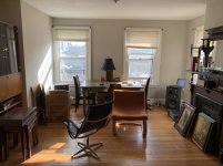
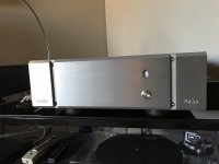
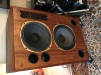
The plan is to hack & stack them with the bottom shelf of the lower one at floor level to make room for some LPs on the bottom and place turntable, amp and Nativ streamer on the top shelf with some cassete deck, CD etc in between.

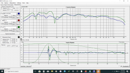
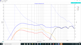
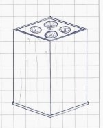
I've ordered enough spikes to create some separate isolation platforms if required. The shelves aren't as solid as they look in the photo so I might invert them and fill them with sand and seal them up for a bit more. dampening.

Choice between store bought racks seems to go from very cheap and Nasty to stupid money very quickly. I know from speakers stands Iv'e owned and built that sand or lead shot makes a useful difference.

I should get this little lot worked up into something useful made of real wood and steel for a bit more than $1000NZD better than the $1000 - $4000 a shelf I've been quoted.

Any thoughts.

Controller Pioneer Studio Speakers

Hi!

A friend had these speakers (Pioneer s-dj05) laying around and gave them to me, he didn't use them because they dont sound extremely loud.... But they work OK for me. The other problem is that the "controller" was missing. This "controller" controls the volume of both speakers, eq on/off, input selection and ON/standby. Its quite nice because you dont need to go to the speakers to turn them on or change the volume.
There are 2 mini din 8a connectors at the back, one is where the controller is plugged and the other is to link the first speaker to the second. From the manual:

controller_con.png

I was thinking about building a controller myself but haven't been able to find any information about it. These speakers appear to be the only Pioneer product that has ever used this gadget.

I found in the manual of the CMX-3000 that it has the same connector to communicate between the cd player and its controller. I measured voltages/continuity to see if the schematic made sense:

din_cmx.png

Pins 2 and 9 (shield) are connected. The shield and pin1 are not connected. Pin 3 has 10v. The rest is very close to 0v. Given the fact that pin3 could be TX, it makes sense that is high (being the speaker the device). But all the rest is not ok.

There is a nice description of the serial protocol in the manual of the Elite SC-05.

It could be serial, but some things dont add up:
- It is mentioned in the speaker manual that once the controller is connected, the volume pot at the back of the speaker is bypassed. Therefore, some pins might just be shorted by the plug to let the speaker know that the controller has been plugged or the controller sends a constant stream of commands.
- The "control out" at the back of the speaker doesn't have voltage on any pin. I would have expected something on the TX too, unless the speaker deactivates the serial module when no controller is plugged.
- The controller volume knob appears to be a pot instead of an encoder (it has limits)
- The buttons on the controller are just momentary push buttons

So, it could also be that pins are shorted by the buttons of the controller and that the volume is just an analog signal.

I opened the speaker to see if I could trace the signals from the connector, but everything seems to be enclosed in an epoxy blob.

I would love to hear ideas or experiences with this controller.


Thanks and regards!

mt different m whats happening

As many of you know I have been trying for several months to use the Seas nextel (w18nx001)drivers as a replacement for the corroded mag (w18e001) drivers in my small Thors. The nextel drivers sound good and although they do some things in the midrange that make them sound excellent with voices and guitars they lack the bass and exacting clarity of the original mag drivers. Out of frustration I decided to change one of the drivers back to the mag driver. the bass filled out and gained about 5 db and the clarity improved and the soundstage and even the imaging seem to be slightly improved. Of course I do not trust myself so I have to ask. why? the bass should have been reduced the nextels are more sensitive. did I create a 2 1/2 way speaker?. what is the penalty? it is no longer a true mtm design or is it? attached are a comparison of measurements the positions are slightly different so the room modes may be different the other is the xsim showing the drivers.

Attachments

  • Screenshot (116).png
    Screenshot (116).png
    381 KB · Views: 194
  • Screenshot (117).png
    Screenshot (117).png
    320 KB · Views: 185

Building a mixer for live vocal FX

Hi!

I have been thinking about learning electronics the last year, but today I really got a kick to start learning.

My girlfriend and producer/bandmate is a singer and has been using guitar pedals and kaoss pads live for vocal processing. Today we talked about that it really doesn't exist a mixer that suits her needs.

I'm a 25 year old musician with medium+ soldiering experience and I'm pretty confident that I can learn what I want to learn (in life). But, I need some thoughts about my dream to build the complete vocal FX mixer. I'll list all the things I'd like the mixer to have and then I'd really appreciate if you guys told me your honest opinion if my dream is completely unrealistic or if is workable.

The mixer needs these things:

1. MIC INPUT with 48v phantom power
2. A good clean preamp with about 50-60(?) dB of gain
3. The dream would be a three band EQ with the mid band to be variable.
4. After the EQ, I need it to have two mono sends with pots
5. I need two foot-switch inputs to be able to bypass the sends with a foot.
6. Both of the sends needs stereo recieve inputs.
7. A mix knob for dry wet
8. One left and one right pan pot (like in pro tools)
9. Stereo TRS outputs


Okey. I can see that this is ambitious. And I know about the Radial Voco Loco, but it doesn't have foot switches, which is the unique thing about this (yet to be build) box.

thanks for your time
Reknes

Bulb Replacement

Hi,
I want to change some bulbs on an old Rotel receiver but on looking the bulbs are wired directly. Anyway, I am interested in changing them for LED’s but don’t know which resistor to use. I’ve had a look at some 5mm LED’s and they are 3v.
According to the service manual, the setup shows 8v and 150mA. I’d be grateful if some could tell me what value resistor to use.
Thanks

Power transformer leakage in Phase Linear 700

Hi Friends,
I am rebuilding a pair of Phase Linear 700 series II's with new White Oak Audio control and back-plane pcb's. With most of the mods completed on the first amp, I am measuring a voltage 'coupling' or leakage between the primary and secondary.
With a Fluke DVM between the primary coil (neutral side) and the secondary winding centre-tap; there is 62 VAC, dropping to 43 V when the meter is shunted by a 1 Meg resistor...and down to 0.64 V with 10k shunt.
Just wondering if anyone has issues with primary to secondary leakage in power transformers, acceptable limits, etc,
Thanks and Happy New Year, Peter in Canada

PS; the PL transformer apparently is the most reliable part of these amplifiers and I have found no documented issues

Attachments

  • DSCN1213.jpg
    DSCN1213.jpg
    980.2 KB · Views: 451

Vituix help

I have looked at threads, and tutorials, but cant figure out why my graph readings don't change on the crossover page. I can put any component in the crossover circuit, and none of the graphs move. The original graphs made by the speaker files are present, but nothing changes. Is there a more complete turorial somewhere on line? Thank You.

Soldering two piece spades

Hello,

New user trying to learn. I've started simple with some custom length cables as I experiment with my stereo gear.

With two-piece spades (collar and spade prongs) the instructions are to thread the cable through the collar and 'mushroom' the copper strands over the opening. Then screw on the spade prong.

Is there any value in dropping in some solder into the middle of the strands to ensure a solid connection and anchor point with the spade collar?

Thank you,

Cy

Shallcross 6 deck, 27 pos switch

Really nice switch with 6 decks, single pole per deck, 27 positions. Make before break contacts. Asking price USD$120

Attachments

  • A4DFC1C9-1CE0-4046-AF2D-7AFE2BBB9139.jpg
    A4DFC1C9-1CE0-4046-AF2D-7AFE2BBB9139.jpg
    778.6 KB · Views: 175
  • E08E3C15-612D-4F3A-9947-09915E795E7A.jpg
    E08E3C15-612D-4F3A-9947-09915E795E7A.jpg
    761.4 KB · Views: 165
  • 307860ED-0AAE-443B-B564-D6DD87178980.jpg
    307860ED-0AAE-443B-B564-D6DD87178980.jpg
    724.9 KB · Views: 155
  • AD06C77A-E7EF-44B6-84AD-C0A5AA190880.jpg
    AD06C77A-E7EF-44B6-84AD-C0A5AA190880.jpg
    814.8 KB · Views: 149

Nanjing TM-85 Glass Vacuum Tube Datasheet

So I found this listing for a fairly big vacuum tube called a TM-85 and it's cheap, roughly $7.

The thing about it is that I can't seem to find a datasheet for it. I asked the seller to know if there's a piece of paper or something in the box that could maybe be the datasheet, but he said there's nothing in the box.

When you search online, the only things you find are either listings for it or some pictures of an amp that uses it.

Has anyone worked with this tube or do they have the datasheet for it? Seems like a good tube to make a series pass regulator with or maybe even a class A amp!

Thanks!

Rockford Fosgate Prime R1200-1D V1.0

Looking for a little help on this Rockford Fosgate R1200.1d V. The amp is in protect. I have pulled the outputs. I pulled 2 drivers (low side) because I had 23 ohms between gate and drain of Q513 and Q514. I pulled the IRS2092 and the 23 ohms went away. So I replaced the IRS2092. But soon as I applied power the 2092 went up in smoke. Fixing to pull the IC again.

Attachments

  • 20200303_133133.jpg
    20200303_133133.jpg
    1,006.9 KB · Views: 134
  • 20200303_090517.jpg
    20200303_090517.jpg
    984.3 KB · Views: 125
  • 20200303_133128.jpg
    20200303_133128.jpg
    1.1 MB · Views: 141

yamaha amp headphone hiss

I have a Yamaha RX-V670 amp. It sounds well but has quite a hiss through the headphones in both channels but a bit louder in the right. It's the same no matter which input I select and doesn't respond to volume changes. That is with no audio signal and turning up the volume, no difference is heard with the hiss. I don't have speakers to hook up yet so I don't know if the problem exists there or not. Any ideas please?
Regards John L.

Replacement for Energy 2.1e?

Hello all.

I have a pair of Energy 2.1e's, the silk dome tweeter type, and the sub that goes with it. I have replaced the amp in the sub as the nasty STK based one that came with it bit the dust. I am currently running the 2.1e's from a LM3886/DC bias amp kit I threw together, and a PCM1794 DAC that I have assembled.
As an aside, I've tried all sorts of op-amps in the PCM and for some reason the OPA2134 I/V & OPA1611 output combo just kicks *** with these speakers.


...And that's the issue. I'm thinking of replacing them when I upgrade to one of those wonderful neurochrome composite amp kits in a month or 2 as I love the way these things sound, but they're starting to fall to bits. I was thinking of replacing them with something like this: Link 1
...Not necessarily with those cabinets, I can get better ones; I've just heard great things about that speaker combo. Some of the SEAS and SCANSPEAK gear looks pretty neat too, and I was hoping someone here might be able to offer insight about what kit speakers out there might possess the sound that these Energy bookshelf speakers have that I love so much.
I have, in my life, some wonderful children, and I adore them enough to burn most of my spare capital on them, so my budget is not huge. say 1-2k? Can it be done?


Thank you in advance 🙂

RPI based preamp. dac. and streamer.

Hey guys,

As i require a desktop pre-amp, Im planning on building an High-end integrated unit built around a Raspberry pi 3B+.

Ideally this would have a few inputs, a headphone output and a RCA out to my Stereo power amp. Raspberry pi would have a ~1.5" screen and some GPIO buttons to control play/pause/next/previous. Volumio would be the software of choice Feeding a ALLO Boss or Katana.

Im wondering if this kit would be a decent starting place to begin.

Is there any other kits that would provide a higher quality sound?

Any other suggestions or similar builds are welcome!

Any Flex-48 knock-offs out there?

Seems like these would not be the hardest thing in the world to emulate, and I think it's a brilliant concept.

Flex-48 Adaptive Treatment System
Flex-48 Adaptive Treatment System @ TrueSoundControl.com – True Sound Control

My question is, has anyone already tried to build something similar?

In the past when I've looked into building something similar using thin plywood and or perforated metal for the outer curved part, the long retaining edges were a detail problem because they were constantly under stress. But I didn't have a router back then, and could probably use a table saw to slot a 2x2 right.

I never thought of using clear acrylic, and never considered leaving top and bottom open. I think Acoustical Fulfillment really hit one out of the park on this one, but I'm too cheap at the moment to take the splurge.

Any DIY Flex-48 knock-offs out there?

I have this small picture frame from 20 years ago that is very similar, always liked that frame. Maybe will post image of it later. It's horizontally oriented though, not vertically.

Attachments

  • soundc-3.jpg
    soundc-3.jpg
    115.6 KB · Views: 103
  • SoundControl-2.jpg
    SoundControl-2.jpg
    38 KB · Views: 105
  • SoundControl-1.jpg
    SoundControl-1.jpg
    85.5 KB · Views: 108

Listening room help- doorways

Hi all- moved into a new apartment. Working on figuring out speaker / rack placement in a room that ain’t so perfect.

My main question- is I have an open doorway to the kitchen in between the speakers- how bad is this? Back walls have some windows that I can put thick curtains down when listening...

Also the right side wall has a doorway to a hall, currently as in the picture there’s a glass pane door that I can either: leave open as is, replace w a solid door and close for listening, or take it off all together, there’s no practical reason to have it there (would never need to close it)

Pics attached..

Width of front wall 14’ 2”, length of room is 15’

Attachments

  • B7C39E93-A3BB-43CA-99B5-E2A895576BB2.jpeg
    B7C39E93-A3BB-43CA-99B5-E2A895576BB2.jpeg
    255.7 KB · Views: 128
  • 23D225E7-5527-4254-A3BC-34AABFB2AABE.jpeg
    23D225E7-5527-4254-A3BC-34AABFB2AABE.jpeg
    257.9 KB · Views: 125
  • F81C417D-02BC-4539-B1A4-26531FDDE487.jpeg
    F81C417D-02BC-4539-B1A4-26531FDDE487.jpeg
    268.9 KB · Views: 116

riaa amplifier

hello,
many years before i made a RIAA preamplifier. The circuit was found in a audio magazine, which i don't have anymore, so i built it up and it was working just fine for several years. Theese days i am going to buy a new turntable and want to use this preamplifier. On the photo (the riaa circuit only) you can see the exact same circuit as mine exept the passive riaa filter component values.
In my circuit the riaa filter values are: R6=29.4k , R4=6,1k , C6=82n , C7=22n and everything else, topology and values and tubes are the same.
Can anybody tell me the differences between those two circuits? I can understand that the differences will be in the responce curve but in which way?
Should i try and listen theese two circuits and keep the one that i like more?
thank you

Attachments

  • riaa.jpg
    riaa.jpg
    128.2 KB · Views: 966

Free - Dayton Audio DTA-1 (Australia)

The clean out continues and I have a Dayton DTA-1 which is similar to the old Sonic Impact of ages ago. Very little use and can run off batteries as well as a 12VDC wall wart.

Dayton Audio - DTA-1 Class D Digital AC/DC Amplifier 15 WPC

Uses the Tripath TA-2024 and good for around 8W-10W of surprisingly good sound. Needs a 12VDC 2A power supply with 2.1mm positive (5.5mm OD x 2.1mm ID). Do not exceed this voltage as it will fry. The knob has been changed to one that is easier to use as I found the original too flush with the body but will include it in the package.

I'll cover the postage to it's new home.

Attachments

  • RZ_DTA1.jpg
    RZ_DTA1.jpg
    67.9 KB · Views: 139

Meadowlark shearwater hot rod crossover diagram?

Meadowlark shearwater or similar crossover diagram? [8545/D2905]

I have recently acquired a pair of ScanSpeak D2905 + 8545. In my search for a matching crossover, I just stumbled upon the Meadowlark shearwater hot rod speakers.

I would be really interested in seeing the crossover design used in these, if somebody has it.

Recommendations for other crossover designs for these units would be appreciated as well 🙂

TIA

Recommended cone driver for mid horn?

There has been a lot of discussion about cone drivers for multi entry horns but I still haven't seen any mid drivers that look optimised for horn load - with the exception of some JBLs.
Anyone know any other drivers that fit this spec.?
Basically a cone version of a compression driver.
That would typically be short coil, extended field for maximum efficiency.
Lots of inductance minimisation/flux stabilisation would be nice too, copper plated pole piece, aluminium plate on top and conductive sleeve inside.
Also aluminium ribbon voice coil (or maybe square wire if two layer inside/outside) for minimum mass to extend the top end.
A carbon voice coil former to further reduce the mass seems obvious but I've never seen this in any driver so a bit much to expect.

David

eBay VU meter circuit

I am currently working on a DAC/tube headphone/preAmp project, where I would like to add an analog VU meter like the ones found on eBay rated at 500µA.
I did manage to find some suggestions for a driver circuit, and I think it would make sense to draw inspiration form the circuit in figure 6, since the author says its intended to be used with the eBay VU meter.

Then it came to my mind that the scale on the VU meter is logarithmic while i am not sure if the op-amp circuit is. The VU meter is first of all a show-piece, so it does not have to be precise, but it would be best if its somewhat accurate. Can anyone tell me if the suggested circuit will actually work? or maybe point me in a direction of a circuit that will work with the VU meter?

I know there is a ton of driverboards on ebay, but I would prefer as solution that is integrated in my circuit, also so I can gain some knowledge about these meters.

Should I Sell the Cute little class A diy monoblocks?

I thought I was so clever buying a used pair of Pass diy monoblocks
while my Cary was in for service. 7 wpc of class A from monoblocks was
an irresistible temptation at $350. + $75 to have a qualified tech
look for correct assembly, upgrade the resistors and the power supply
to 24 volts from a better company. So all in at $425.

The sound was so good thru my of Tannoy FSMs that I read up on the Pass
Amp line and bought an XA 25. So the little buggers cost me another
$2K-cost of xa25 less Cary proceeds.

I loaned the monos to buddy who immendiately has someone who wants to buy them.

Not sure why I should keep them other than female vocals sound pretty amazing at low volumes and they are cute as bug's ear.

Suggestions??
Price?

Attachments

  • IMG_5442.jpg
    IMG_5442.jpg
    543.8 KB · Views: 264
  • IMG_5825.jpg
    IMG_5825.jpg
    589.3 KB · Views: 267
  • 748CC3AE-92B1-411F-AAB0-89E46978B58A.jpeg
    748CC3AE-92B1-411F-AAB0-89E46978B58A.jpeg
    705.2 KB · Views: 271

Ground bias and simulation

Hello,
I have read this 2 threads :
https://www.diyaudio.com/forums/solid-state/5897-leach-amp-bias-star-ground-questions.html
https://www.diyaudio.com/forums/tubes-valves/102790-ground-dc-bias-supply.html

I still have some questions :
- The bias supply is a very low current ground.
Yet it is part of the signal of the output power tube signal, so it should be close to the power tube ground.
The big capacitors a these points create a very high current ground.
To me it will modulate the bias supply ? Is there a better place ?
Should I think in term of ground current, or in term of "this belong to the same signal" ?

- Is it possible to simulate the noise in the ground in LTspice ? If yes do you have an example I could not find anything beginer frendly on the web.

Thank you.
I will use this circuit with a separate bias winding of 50V:

Mark levinson lnp2 module help

Hi everyone

Need some advise here

I got a mark levinson lnp2 preamplifier and although i love it so much i have problems with the module. Overheat and start popping
I look at the replacements and there is no original. The replacement that are not original are quite expensive. 300usd a module and no idea how it sound

Does anyone have any idea how to solve this? Can i make one myself?
Thank you

Anthony

Question on binding posts

Up till now I have always used terminal cups, and I have never been impressed by them... they always seem a bit fragile.

So now I am trying Dayton Audio Heavy Duty Binding Posts. No instructions or drawings were provided, and there is no guidance on the Parts Express website.

Having never used them before, I am confused by the two nuts, two star washers, and the terminal tab / solder tab. I assume that after the post is inserted through the cabinet wall from the outside, the hardware is attached in this order: nut, washer, terminal tab, washer, nut... yes? Or perhaps it is washer, nut, terminal tab, washer, nut... ?

Attachments

  • D-hd-bp.png
    D-hd-bp.png
    48.4 KB · Views: 116

Needing some PCB help

Needing some PCB help - resolved

Considering my health and age it is unlikely I will have a need for more than a once off PCB. It must be over 40 years ago since I last made a PCB and things have changed a lot since.

I ordered a PCB from China and what duly arrived is different from the order and has a number of design errors on it. Seller is unhelpful. There are no other PCB's available that come close.

What has arrived can be hacked around but I prefer to have a better version.

If possible I prefer not to fuss around with chemicals etc. and submit a design online instead.

Please, those who have gone through this, what (free?) software would be simple to learn and who are one of the better PCB manufacturers that will make a small quantity of preferably no more 2 or 3 boards (perhaps 5) at a reasonable price? Delay in delivery time is not a big issue, I do not need it yesterday.

Second question: In what format do the PCB manufacturers need the file?

edit: Enough information by all the particpants has been offered for selecting and working with modern PCB design software.

Potentially no longer a new PCB is required due to an alternative solution that results in improved longevity.

Thank you!

The MONGREL (supersym II)

Ahhh - At it again , to refine what I know already works. The original supersym(s) are now a year old , they have not gone to the fiery pit :flame::flame: ... they even are very pleasing to listen to 😀 .

I just had to try for more stability , lower THD and the "MONGREL" is what I came up with. It is STILL the same core circuit-a single ended LPT with the Otala/Hitachi VAS but with a few improvements.

1. - 2 current sources and a cascode on the differential - much better linearity and PSRR in the "front end" , also.. ABSOLUTE signal symmetry at the input pair.

2. - lower differential current,slightly higher VAS current - better for running standard type 2 or 3 EF's with difficult loads and better linearity .

3. - Standard double EF but with type 3 current sources - carrier "suckout" ,less Xover distortion.

4. - better Vbe (complimentary)


Picture 1 is the circuit.

Picture 2 is the BEST 🙂 FFT I have ever produced from a class B. The distortion is damn low , too. (pix 3)

On this set of simulations , I nearly was able to go to sub 10pF for Cdom and the simulation did not "choke". Soon I will tweak the open loop gain and global compensation but I suspect it is already close by the impressive stability I have already observed.
It seems Mr. Carlos (DX) saw the first one (supersym) , because now his amps are "locked and loaded" full of CCS's , this is how you really use them .... each of the 4 (CCS's) has a very valuable electrical as well as a noticeable sonic improvement. We don't waste valuable part around here !!

OS

Any comments or suggestions would be highly appreciated.

Attachments

  • mongrel.gif
    mongrel.gif
    94 KB · Views: 13,811
  • FFT 2_3 power.gif
    FFT 2_3 power.gif
    21.4 KB · Views: 12,220
  • full power thd.gif
    full power thd.gif
    12 KB · Views: 11,046

Convert Or Add XLR Inputs To Power Amp?

This is almost embarrassing to ask on THIS forum. LOL But here goes..... How can I add XLR inputs to a given amplifier, which only has the usual RCA inputs? Would it be different with different amplifiers? On one of my two Threshold S-300's it has the "E" mod, which includes XLR's, and RCA's, and a switch to choose between them. That's what I would like to do to other amps.

I'm shopping for a third amp, so that I can tri-amp with me DQX-2496 xover. This would broaden the field a lot, because I would like the third amp to be balanced also.

Many thanks!

PLL 4046 sanity check please

Hello:

So I am building an application specific oscillator, and have attached a partial (work in progress) schematic. It is a straightforward N=128 frequency multiplier synced to the AC line, with an output freq of 7.68 kHz. I am really interested in anyone's experiences with the low pass filter for the phase locked loop. I have looked into numerous app notes and schematics off the web for simple equations to help me design the LPF without having to go back to feedback control systems.

I have found examples of resistors in the LPF that vary from 1 Meg to 5k, with similar valued capacitance and similar frequency ranges. It appears there is not a lot of consistency. I have used the equations provided in Philips 74HC4046A http://www.datasheetcatalog.org/datasheet/philips/74HC4046A.pdf, and came up with the attached results. Do they look reasonable? I don't need extremely fast settling time; just a stable lock to 60 Hz.

VCO output = 70 Hz at 4.1V
VCO output = 50 Hz at 0.9V

Kp = phase comparator gain = 5/(4pi) = 0.4
Kv = VCO gain = (2fL * 2pi)/(4.1-0.9) = 5026
Kn = 1/N divider ratio = 0.0078125

choose settling time = 0.25 sec, damping ratio 0.7

wn = 5/settling time = 20

t1+t2 = Kp*Kv*Kn/wn^2 = 0.039 sec

select C2 = 1.5 uF

R4 = [(t1+t2)*2*wn*DF - 1] / (Kp*Kv*Kn*C2) = 3.9k

R3 = t1/C2 - R4 = 18.2k

Attachments

Taramps HD 8000 remote turn on circuit

Taramps HD 8000

I have a Taramps HD 8000_R2 1 ohm version that had a blown power supply that I have repaired. The problem now is that the amplifier powers up with only B+ and ground connected and NO remote voltage connected.

When I connect remote voltage to the amp, the amp shuts down.

Any ideas what this could be. I haven’t encountered this before on a Taramps.

Thanks,
David

Ports, passive radiators and room coupling

Basically my dilemma boils down to room coupling.


Its basic knowledge that passive radiator models the same as port for ventd enclosures, with the mian difference being a somewhat steeper rolloff below the fs, as opposed by considerable space taken by ports tuned low.


What I could not find much info on is the difference in room coupling of these. The higher the velocity of a speaker (or a sound source) the poorer it couples to the room, which is why classic 8" midbass dirvers give a perception of much greather authority than 4-5" long throw midwoofers, even if these extended lower on paper, at least from what I read.


In my case I have a 5" midbass which will be augmented by a sub. I was wondering how much authority would a 5" have at 80-100 Hz when I thought that I could provide a larger radiating area with less excursion by adding a passive radiator. I found two SB PRs, a 6" and 5x8", but in both cases these would peak at around 60 Hz, where there is realtively little output from the midbass and its about 10 db below sub levels. So basically simulation tells me that I would not gain much LF output, but perhaps I would gain some more authority in the bass?


What is Your experience in PR vs vents in term of room coupling? Does larger radiating area of a PR make a subjective difference in how speakers load the room?

Plywood alternative (aluminum)?

So, Im waking up in the middle of the night realizing my mind has not shut off, pondered building 2 cabinets from corian but am finding it difficult to source locally.. everyone has gone quarts. Meanwhile I just spoke to a waterjet cutting company and he made a comment that 1/4" 5052 (32 sq ft) is cheaper than the corian! His 1/2" is only slightly more!

So, do you fine folks think 1/4" aluminum is stiffer than 3/4" plywood?

Not to start a war, the next question is for the folks who believe a cabinet should be dead, and not impart any coloring to the sound, Aside from visual warmth, would anyone know of any reasons why it might not sound good?

I have read the threads where some feel strongly about certain woods imparting warmth.. For obvious reasons id prefer not to compair wood against metal as I know its near and dear to what they feel is important to them..

Thanks in advance!

Blaupunkt X-240 (1979)

Hi All,
My local shop has a full set of BLAUPUNKT X-240 (1979) in working condition, it will probably need a full service which I can do myself. If its not working he said I can bring it back, included is pre & power amp, cassette deck (no wear on head) (probably needs new belts) tuner, record player (without cartridge) and a pair of Dual CL 143 speakers, price is 150 euro and in good external condition, any thoughts ? worth it for collecting?

Anyone have one, how does it sound?

Altec 825's - 4 total

I was going to re-furbish these, but I don't have the time and space to be able to do so with the rest of my projects. So, I'm going to sell these 825's.

I have 4 of them, all in similar shape. They look to be original Altec, but I can't confirm. They have had some of the, IMO, wise bracing added in a few spots. The port plates have been modified, but that's just a piece of plywood, so you can configure however you like. I have the rear plates for all of them as well.

Local pickup obviously. I live between Austin and San Antonio. I can deliver to Austin/San Antonio for a bit of extra cash. I also periodically go to DFW, so that's a possibility as well.

$250.00/pair, or $400.00 for all four.

Altec 825 - Google Photos

Cheers,
Gable

John K's Nonlinearcompliance

I'm wondering if anyone has played around with John Kreskovsky nonlinear compliance excel spreadsheet. I can't get the distortion chart to work in excel 2013. Also what can be learned by the graphs? Is there certain t/s parameters that result in lowered distortion once the driver is in a sealed box?

Also, can I use klippel data to input a compliance shape factor.

Thanks.

How does Q point affect gain?

Let’s say I have a transistor class A amplifier circuit using a depletion mode FET. I have the load and the source resistor values already picked out to provide the right amount of gain and the source resistor is cold biased to provide asymmetrical clipping. Now let’s say suddenly I must substitute my depletion FET for a similar enhancement type FET. When I set my gate bias up so that the Q point is in the middle of the active region, will that change the way the current drain and source resistor values affect the gain of my circuit? Thanks.

WTB Thiel SCS tweeter

Hi everyone

I have a pair of Thiel SCS monitors that I just picked up that need replacement tweeters

The SCS uses a coax driver from Seas *(the 17RE series, 170mm , 2 way , see attached spec sheet)

The tweeter uses a 26mm fabric dome, with neo magnet that fits in the voice coil opening- the woofer cone acts as a horn for the tweeter, *(see attached photo)

The tweeters are easy to remove with only a slight push from behind


Anyone have a pair of tweeters?

* ( I believe that the correct tweeter model is 25TFFN/X)

Much thx

SW

Attachments

Budget DAC decoder boards out of the box

I've done deep dives through a number of threads on the ebay / aliexpress i2s dac boards for ES9038Q2M, ES9018K2M, and similar. Most of these boards seem to huge flaws in the output stage, power supply regulation, etc that makes them sound horrible without significant modifications.

After going through many of these threads, it makes me curious... Has anyone found any budget i2s dac boards (ES9xxx, AK49XX, etc) that actually sound more or less pretty good "out of the box" when powered with a good power supply and hooked up to a quality usb to i2s converter? Or are they all pretty terrible without significant modifications?

RPI dual mono DACs related question

Hi guys,
I have a wish to use RPI in mono mode. Connecting a single speaker and getting all sound (not missing left or right channel). Aim is to use it on a single car dash speaker (vintage Alnico) for mids and highs. There is software solution on combining both channels but i would like to go with DAC based.

I see on the market there is some Dual Mono Raspberry PI dacs. Durio sound , Ian Canada one, and expensive ApplePi. If I would use any of these DACs, would it be the case that i can connect to any of two RCA outputs and will hear the same sound (now splitting to L+R done)?

Proper outputs for F-5 V3.0

Several years back I bought the F-5 V3.0 boards and now I’m finally getting around to work on them. I’m sure this comes up, but couldn’t find anything. What are the proper outputs for the V3.0? The FQA19N20 and it’s complement seem to be obsolete. I’m guessing there is a reason they swapped from the IRFP240 and it’s complement. I’m placing an order now, but not sure what to purchase. Any other parts that might be obsolete and need a replacement? I can’t seem to find a BOM for the V3.0.

Thank you,
Dan

WTB: Hypex Amp(s). Needing 2 channels.

I need some very low-noise amplifiers for my testing purposes and the Hypex seem to be the best value. I would need 2 channels; as much power as I can get (250w/channel would be adequate). Still, I'm on an extremely tight budget since purchasing all sorts of test gear for my website. So, I am looking for used. If you have anything that fits, please let me know.

Thanks,
Erin

DAC for coax out

I'm a total noob when it comes to digital (analog vinyl tube guy), so please excuse this dumb question. I have a old Philips CDB630 with only digital coax out. I want to purchase a good (but inexpensive) DAC for it. What do people recommend, or is it not worth the effort?
DIY, KIT, something? Buy something (old Audio Alchemy?), eBay, got something unused you want to sell?

Mark Levinson LNP-2

Dear all,

I'm operating an vintage ML LNP-2 pre-amp with the meters.
All line sources work fine but one phono-channel is almost dead and the other one works fine.
Strange thing is though that apart from the two Dick Burwen VU modules all modules are the same Line Drivers LD-2 or Fet Input Amplifier Module as they are called.
I've no glue how they get any RIAA correction and what extra phono-stage there is because I can't find any active part apart from one little IC.
Is anyone familiar with this pre-amp and perhaps knows how the phono (MM) works?
Thanks in advance,

Robert

Attachments

  • Levinson LNP-2 internal 1.jpg
    Levinson LNP-2 internal 1.jpg
    389.5 KB · Views: 534
  • Levinson LNP-2 internal 2.jpg
    Levinson LNP-2 internal 2.jpg
    460.1 KB · Views: 543
  • Levinson LNP-2 internal 3.jpg
    Levinson LNP-2 internal 3.jpg
    527.2 KB · Views: 868
  • Levinson LNP-2 pic_1.jpg
    Levinson LNP-2 pic_1.jpg
    499.5 KB · Views: 551

GZHA 1.1200D big current, excitement amplifier ??

Hi all!

I have such an amplifier.
My problem with this is that I could rebuild the control panel from the dragster dad1201 drawing I found, but when I assemble it feels like it is drooling, there is a huge amount of resting current and even noisy HDRV (Top of the Rectangle).
If FeedBack is not connected then there is a nice rectangle on the output even after two coils, of course this is not good.
I think the controls on the control panel are good. Ideas? Could they be measurement images?

Same board

Power Acoustik A3000DB
planet audio tt2250d
kole q1-3000D
Dragster dad1201

Strange Hum Problem in Phono Stage

Hi,
I've built three identical phono stages based on the Phono Dude phono stage which uses 5755 input tubes. The strange thing is one hums when I plug in the turntable, the other two are silent. The builds are exactly the same. I'm using the same record deck, power amps, speakers, and mains leads. Absolutely everything is equal.

Without the phono leads from the deck plugged in all three have identical low noise and no hum.

The only objective difference I can pinpoint is the grid reference resistor on the input tube is around 1cm longer than the other two. The 5755 runs with a directly earthed cathode.

Any tips anyone can give me are very welcome. Thanks!

Help designing DIY box for RSS315HF-4 12"

Hi all, I should start by saying I'm a complete noob to box DIY speaker building as well as forums, so I am sorry if I get anything wrong/say something stupid but is all a learning curve..

Having spent the last month trawling the internet trying to work out the best way to go about starting my first DIY project and, seeing as I had loudspeakers but no sub, I decided to go for building my own. I spent many hours trawling threads and watching youtube videos I decided to order the RSS315HF-4 12" from Dayton, largely due to lack of options in the UK.
Now I have my driver I think I have decided to start with sealed and then maybe build a ported design at a later date. I found the zaph audio design and was about to go ahead and follow that but then realised I would probably want to build a passive design as the main reason for wanting to learn DIY speaker building is I aspire to build some sort of smallish rig for parties in the future. So I guess my main questions are:
- is it a bad idea to go for a passive subwoofer given my situation?
- if no, how would I go about modifying the design to work for a passive box?
- and does anyone have suggestions for 4 channel power amps which would allow me to add more speakers in the future?

Sorry for the long post and again if something doesn't make sense due to lack of knowledge, hope someone can help!🙂

Pair of EAD E60 fullrange drivers successor to Jordan JXR6HD

Hi
This is a mint pair, to be sold boxed in all original packaging and supplied with their measurements from the factory and original invoice. There are no marks, except the solder on the tabs. They have only been lightly used.
I am selling them for half price including shipping within Europe: £100 only for the pair.
michael@arcadianestates.com
Will ship globally for the extra cost.
Payment by paypal only.
Thanks.

SD Card Memory FLAC/WAV 192/24 player - ESS crescendo II - AK4495 - DV20A

Hi all,

Haven't seen this one around on the forum so I thought to give it a shot.
Been on the forum for a couple of years but haven't contributed yet and thought now is a good time 🙂
I've been playing around with a couple of SD card FLAC players for a while now and ran into this one on eBay:

Finished Digital Turntable Lossless Music Player Ape WAV MP3 AK4495 DAC | eBay

Decided to buy it and see how it can be modded to sound any decent.

An externally hosted image should be here but it was not working when we last tested it.


After opening up, the player shows a modular approach. The SD card section is based on the ESS Crescendo II soundbar chip. I spoke with my contacts in ESS to get confirmed that this chip is actually real and capable of doing FLAC decoding on the fly.

An externally hosted image should be here but it was not working when we last tested it.


The ESS chip reads SD cards and USB sticks, clocks the data through it's built in DSP blocks, which at this point should be all 32bit wide audio path.
Apparently this is also where it decodes FLAC up to 24bit 192ksps and does digital volume control.
Via i2s and spdif the resulting digital audio is available.
Seeing the small smd crystal oscillator that clocks the whole thing, I'm thinking there may be something to optimize here.

The second pcb is the i2s AK4495 and power supply board.

An externally hosted image should be here but it was not working when we last tested it.


First thing I had to do was a checkup of the infamous dipswitch that controls the filtersettings of the AK4495 and of course the dipswitch design flaw is present in this board. Removed and replace by 2 jumpers.
Second thing, check the level of pin 5, the SSLOW signal. Luckily this is connected to GND already, so disabled.
The SSLOW signal makes the filters extend their roll off for use at lower than 44.1 kHz sampling frequencies, if I'm interpreting the datasheet correctly, page 28:

http://www.akm.com/akm/en/file/datasheet/AK4495EQ.pdf

The next thing was checking the output circuit. They used a double opamp by JRC, the MUSES8920
I'm not familiar with that chip at all, I'm definitely going to experiment changing it for something else.

The output is connected via 22ohm resistors, thank goodness no crapacitor in the output... BUT because they apparently used 5% resistors or something there was 45mV DC offset in one channel and 16mV in the other. Not so good.
My mod shows a 47K5 fixed resistor / 50K trimpot pair over each DAC output resistor to level away the DC offset. See the image above.

I have to say my first impression, after the mods, is quite positive. I am going to do a lot of listening now and prepare a list of further mods to improve the way the thing sounds.

By the looks of it, there is room for improvement in the decoupling, power supply, clocking and output filter.

Never a dull moment 🙂

I'm curious to know if there's anyone out there that already has done something with a unit like this.

Cheers, Hans.

Symmetrical line preamp

Hi guys, just idea for symmetrical line amp based on famous one which I've found on this forum. May I use is this way please?
Maybe I can do the same with CF at the ouput like with SRPP on input, so use resistor for up and down CF but with 11k value.
Or, do you have any other symmetrical line preamp which you can recommend please?
Thanks.

Attachments

  • idea.jpg
    idea.jpg
    37.7 KB · Views: 452

New MINI ZEN Headphone Amp PCB group order...

zen headamp info,you can download my protel99se ddb file.

The boards size is 91X64(mm).The price is $4 USD per board.One amp need two piece of PCB. Use CHINA POST(ship) costs is $5 USD.

you need to email me directly to place an order. Instructions on this will be posted to this thread.

Boards, Total = 30 pieces.

My e-mail : zanghb@bjtzh dot gov dot cn

Attachments

  • 87_3.jpg
    87_3.jpg
    42.3 KB · Views: 6,256

LTSpice - comparing 2 simulations

Hey guys, maybe someone knows how to do this.
In LTSpice, is there a way to compare two simulation runs?
For example, say you do a step response and plot the voltage of the node of interest. Then you make a tweak to the circuit and run the simulation again. Now I would like to visually compare the waveform of the previous step response to the current one. Is there a way to do this?
It would be super helpful.

Thanks a bunch!
- Sandro

unsure what speakers

Hi All

For years I have wanted to build speakers but never been able to. Well the time is now. The thing is, I'm not that into high end audio and listed to music on spotify. We listen to a huge range of music, at a large range of volumes and currently have an old logitech 2.1 system. My substantially better half especially, likes a bit of doof doof, so something with good low end or something that has a sub to go with it would be great.

As to why I want to make it, I like to make stuff. I'm a engineer by trade and have access to wood and metal working equipment.

What would you recommend building?

thanks in advance

Denon Tu-500 , No Stereo

Hi, my frined gave me a TU-500 for no stereo operation. Mono signal work for both channels.
FM stereo light work if i bypass HA1156 mpx chip.
Checked front end with my Leader stereo gen for 100MHZ carrier and 19KHz pilot and L+R audio mod.
Front end and IF if fine as I can tune IF stage to compare once demodulate FM carrier versus the composite output of signal stereo generator to be exact minus some usual distortion of signal,
So the front end is a reply of the composite signal that is a 1KhZ L+R audio with a 19KHz pilot all mix together.
I can with my stereo gen have a 67KHz SCA modulation and I can observe it at the input of the MPX HA1156 chip.
Of course replacing, testing all near components near the HA1156 is been done.
All caps are replaced either the coupling one and filter ones.
Did replaced the HA1156 chip, still no success. No Stereo.

So with signal gen at 100MhZ FM carrier with L+R 1 KHz audio and pilot on
I can follow signals on the HA1156 pins.
All DC voltage looks good with a solid 12 V DC .


I have removed the muting signal and the force mono on pin8 to isolate those.
So the HA1156 have now pin2 input which is composite signal, I did injected a direct composite to the pin2 from my stereo gen no difference, still no stereo indication.
Pin6 remains 6,6vdc.
19KHz signal from this HA1156 is solid compared coming from RF front end or pin10 have same frequency of 19KHz compared with frequency counter and a scope.


Outputs pin 4 and 5 have 10Vdc and L+R 1 KHz audio signals mix with 19KHz, this is before the lowpass filtering on the audio signal.


Filter caps direct on pin 4 and 5 are lifted too, so no interference if they are defective.


So to resume:
VR301 cleaned, C303 checked
C304-305 replaced.
C306 checked
C302 replaced
C301 replaced
R308 lifted
R309 lifted
C307-308 lifted
C311-312 lifted
C329-330 replaced
All close resistors measured OK.


Any other ideas where to look for??
Thanks

Attachments

  • 20200110_135847.jpg
    20200110_135847.jpg
    985 KB · Views: 356

interesting OMNI design...

Stuck in my head, input needed

You might find this post interesting if:
- You like thinking about creative solutions for unconventional problems;
- You like unconventional box designs;
- You like more questions than answers;
- You like my weird thinking;
- You like long posts.

Designing the system of my dreams. I want to walk around the room and not deal with phase cancellation or beaming issues. My ideal speakers sound good at any listening position, can play loud, feel like they're 'breathing', and have an immersive and encompassing quality to them. I have boggled it down to some more concrete requirements. Please bear with me as my convoluted brain processes unfold themselves.

My demands:
- Full range system
- Response 40Hz to 8kHz
- Ability to fill 50m³ room (1766 cubic feet)
- Ability to play loud
- Omnidirectional sound dispersion

Let's break those down!
Full range: Self-explanatory. Definitely no crossover.

Response 40 to 8kHz: Okay, perhaps not full full range... I will be adding in biamped supertweeters (sue me!), but I have all that figured out already. These boxes will be run full range without crossover, and 40-8kHz is what they have to cover. I'm asking your help regarding solely these boxes that will be run full range.

Ability to fill room: 50 cubic meters at least, preferably more. The boxes will have to be able to do this without effort.

Ability to play loud: Sometimes I play metal music loudly and then I don't care much about the audiophile characteristics. Often I will turn down the bass frequencies to take some strain off the drivers. That said, I'm probably wanting drivers with above average Xmax, say 3-5mm (about 1/8th inch - 3/16th inch)

Omnidirectional sound dispersion: Here the interesting part begins!

Traditional omnidirectional speaker designs make use of an upward firing driver that shoots audio into a waveguide of sorts, usually a concave cone that reflects audio 360° [attachment 1]. The sound heard would be the sound that is reflected off the waveguide. Unfortunately, this leads to some loss of sensitivity (compared to the point-source measurements supplied by the manufacturer). A driver that is listed as 96dB/m (1W) will most likely measure around 93dB/m when integrated in this traditional omnidirectional box design. (Correct me if I'm wrong.) Loud full range drivers are rare to begin with, so losing sensitivity is tough when my other requirement is for these speakers to play loud.

This introduces some unconventional restrictions on the box design. For the last months, I have been weighing the pros and cons of two options:
- Upward firing driver into a flared conical waveguide [attachment 1]
- Multiple smaller drivers shooting upward into the air [attachment 2]

Let's break it down.

Option 1 - Upward firing driver into waveguide: This is the traditional omnidirectional design. I would want a high-sensitivity driver with a stiff cone that can handle about 40 Watts nominal, and has about 3-5mm Xmax. How about that for asking for the impossible…
Though I do think I would have some options here. For example, the Tangband W8-1808 is rated 93dB/m and 30W nominal, while having a stiff bamboo cone and an Xmax of 5mm (about 3/16th inch). Firing this driver upward into a concave cone might still yield ~92dB/m in the upper midrange and about 90dB/m in the lower midrange/upper bass. Combined with a bass reflex, extension to 40Hz could perhaps still be about 89dB/m, which is not unreasonable, if one considers all my demands. (These are educated guesses.) Often I turn down the bass a little bit when I crank up the total volume, so the driver should be able to play anything above 120Hz or so even louder, whilst the decreased bass in the input signal and a not-very-low Qts cause the conus to stay inside the Xmax boundaries. Extending a little outside of the Xmax when cranked is not a problem IMO.
While I think this design would be possible, it does greatly reduce my options regarding driver choice: not many drivers meet the required specifications. I think most drivers that remain are about 8"-10"-12" in diameter and will have to be cone-treated to ameliorate cone breakup issues. Beaming is not much of an issue because of the waveguide.
( In case of the Tangband: 100L ported box (about 3½ cubic feet) tuned to 40Hz. )

Option 2 - Multiple drivers firing upward: Another way to achieve omnidirectional sound dispersion is by having a driver fire upward. The sound you hear then is for the greatest part reflected sound from adjacent walls, and also the ceiling. This design is tried and tested and works great for omnidirectional sound dispersion, but has downsides. Having the driver fire up into the air greatly reduces perceived sensitivity at the point of listening (3dB/m at least, most likely more), since most waves hit the ceiling and the walls before they reach the ear. However, since no waveguide is hanging above the driver, it is possible to multiply the amount of drivers. For example, one could have 4 full range drivers firing upward in order to achieve omnidirectional sound. This would in turn lead to a higher total system sensitivity and a lower required Xmax per driver. Think of it like an upward-firing driver array… that eliminates comb-filtering because of its dispersion pattern. However, since beaming is a thing, smaller drivers would be required in order to achieve pleasant omnidirectional sound dispersion. Luckily, since there are a lot of small-ish full-range drivers (4" or so) out there, a lot more drivers that fit the specs remain as an option.

Other options that I have ruled out:
Angled bipoles: Nope I don't want the large dead spot down the middle
Angled dipoles: Too much drop in efficiency, especially in the bass
OB dipoles out in the room: Don't have enough space in my room to make those truly viable
So, according to my rationale, I'm stuck at a fork in the road, having to choose between the two options listed above. Even though I'm having tunnelvision and I'm missing lots of stuff, I would still like to compare these two options here. I find it hard to imagine whether they would satisfy my demands. I also find it hard to weigh their pros and cons in relation to the ideal that I have in my head.

Therefore I'm curious to your thoughts regarding the two options that I listed.
- Do you think either would satisfy my demands?
- Would you specifically advise against one of the two?
- Do you have experience with either option? Please share.

(Be kind!)

Cheers,
Raoul

Attachments

  • 1.jpg
    1.jpg
    125.7 KB · Views: 579
  • 2.jpg
    2.jpg
    108 KB · Views: 568

Going Bordeaux tops. Couple of questions ...

I really want quality AMTs in my next speakers. So I am purchasing the top portions of the Bordeaux, but making a couple of changes. I need to know if those changes are possible, without redesigning the xover.
I want to use a larger sealed, or ported cabinet, and do away with the dipole set up. While this will not necessitate a change in xover from mid to tweeter, in regards to frequency or slope, BUT will it change the relative volume of the midbass to tweeter transition? Wont it make the woofer now louder, upsetting the balance?
My other question is, other than killing the back wave for a more expansive soundstage, will the xover need any change due to the midbass no longer being opened in the back? The overall tone should not change due to this, should it?
Thank you
Projects by fanatics, for fanatics
Get answers and advice for everyone wanting to learn the art of audio.
Join the Community
507,624
Members
7,880,747
Messages

Filter

Forum Statistics

Threads
405,896
Messages
7,880,747
Members
507,624
Latest member
Neilonpoint