Hello,
I have read this 2 threads :
https://www.diyaudio.com/forums/solid-state/5897-leach-amp-bias-star-ground-questions.html
https://www.diyaudio.com/forums/tubes-valves/102790-ground-dc-bias-supply.html
I still have some questions :
- The bias supply is a very low current ground.
Yet it is part of the signal of the output power tube signal, so it should be close to the power tube ground.
The big capacitors a these points create a very high current ground.
To me it will modulate the bias supply ? Is there a better place ?
Should I think in term of ground current, or in term of "this belong to the same signal" ?
- Is it possible to simulate the noise in the ground in LTspice ? If yes do you have an example I could not find anything beginer frendly on the web.
Thank you.
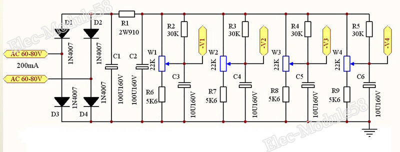
I will use this circuit with a separate bias winding of 50V:
I have read this 2 threads :
https://www.diyaudio.com/forums/solid-state/5897-leach-amp-bias-star-ground-questions.html
https://www.diyaudio.com/forums/tubes-valves/102790-ground-dc-bias-supply.html
I still have some questions :
- The bias supply is a very low current ground.
Yet it is part of the signal of the output power tube signal, so it should be close to the power tube ground.
The big capacitors a these points create a very high current ground.
To me it will modulate the bias supply ? Is there a better place ?
Should I think in term of ground current, or in term of "this belong to the same signal" ?
- Is it possible to simulate the noise in the ground in LTspice ? If yes do you have an example I could not find anything beginer frendly on the web.
Thank you.
I will use this circuit with a separate bias winding of 50V:
You need to create a Localized ground loop:
Connect D3, D4, C1, and C2 returns together. Use very short wires to do that (position the parts so that you can do that).
Then, after that, connect C2 return to R6, C3, . . . etc.
Your schematic shows that, but most builders do not pay attention and actually do that.
Instead, they connect a wire from D3, D4, and C1 to R6, C3, . . . etc.
That will create an External ground loop.
"Attention to Details" works wonders.
The same principals apply to the B+ supply, whether it uses bridge rectification, or center tapped full wave rectification.
"Grounds Are Commonly Misunderstood" - Me
Last edited:
Thank you, I wasn't expecting this answer. Attention to details.
This is exactly what I want to learn, but I am really lost these days.
I feel like electronic is way more complicated in real life versus the schematic. Sometime I almost feel like giving up when I spend days looking for an answer... is it worth it? There are hobby that are more fun and waste less time 😀.
I have a question, it is better to connect the ground from the capacitor c6 or from c1 ? or it does not matter.