Peppy Player Headphone output not working

I built a Peppy Player with Monet and a HiFiBerry and 7" RPi touchscreen. Works great! I would, however, like to remove the HiFiBerry and connect the line output to my stereo. I removed the HiFiBerry and changed the config.txt [volume.control] amixer.control from Digital to Headphone but nothing comes from the 3.5mm line output jack. What else must I change to get this to work. (The line output worked before I added the HiFiBerry but I don't remember if I changed anything else.)

Portable ammunition speaker

Hi,

I'm new to this site and wanna ask for some advice on building my 5th portable speaker.

I was looking to build a portable speaker in a ammunition box, with a wondom jab3+ and a 4s2p battery and a inlay of wood (for stability). I was wondering what drivers to use in it 4,5l internal volume without the drivers. For playing inside aswell as outside.

I was thinking about 3 options:
1:A dual tcp115 vented design with dual tweeters(any sugestions?).
2:A dual tcp115 sealed design with dual tweeters(any sugestions?).
3:A single tcp115 vented design and a sealed 3 inch full range driver.

Let me know what u think!

Thanks in advance,

Martijn

Look, Ma, No Coupling Caps! A Transformer Coupled VFET/SIT Amp Design

Before I discovered VFETs/SITs, I was a vacuum tube addict. Now I have seen the light, but some old memories are starting to resurface. More iron has been creeping into my builds, and my thoughts have been turning to transformers - interstage and output transformers.

I am very happy with my last inductor loaded VFET/SIT builds and I thoroughly enjoy listening to them, but the itch has started again. I am a serial amp builder.

I like trying new things, and luckily, a new idea came to me. I remembered that I have a pair of interstage transformers from my previous life. They were used in a 5842 tube / 45 tube amp. They are Magnequest RIT-5 (5k:5k) gapped for 50H 20mA DC if I remember correctly. I still have these monoblock amps but I haven't used them for years. I can't remember exactly when I built them, but it was 20 or 25 years ago. So, these interstage transformers will be part of my new amp design.

When I was young and into Directly Heated Triodes, I was greatly impressed with Susumu Sakuma and his Direct Heating web site. His designs with transformer coupling, power triodes as drivers, and chokes galore were eye candy to me. Sadly, he has passed away, but his ideas live on. This new VFET / SIT amp was inspired by his designs.

Having decided that I wanted to build a transformer coupled VFET / SIT amp, I researched what has been done before. I found works by Jean Hiraga, Nelson Pass, Michael Rothacher, and others. So, I'm not the first with this idea. However, my idea is a little different in that I will use a source follower output stage, and I haven't found any references to this mode - probably because engineering wise, it is wasteful. But, I'm not constrained by cost (within limits) or practicality so I can live with a voltage amp stage and an interstage transformer which would not be necessary with a common source output.

I ordered a pair of J&K Audio Design's version of the Tango FG-50S output transformer so I'm starting this new build journey. It'll take a month or two to get the transformers but meanwhile, I will build and test some prototypes with choke loaded output.

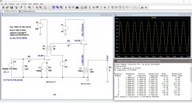
My first version will be 2SJ28 driving 2SJ28. I also have some 2SK180ES and THF-51S for outputs and some Russian 2P926B for voltage amplifier. The larger SITs will require a bigger driver voltage swing for full power; that will need some experimentation.

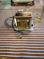
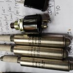
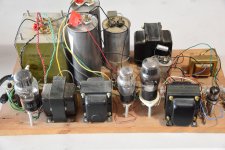
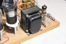
A couple of photos below show my breadboarded 5842 IT 45 tube amp monoblock with its LCLC power supply, interstage transformer, and output choke and parafeed transformer. The interstage transformer is shown in the last picture.

Attachments

  • LTSpiceSim.jpg
    LTSpiceSim.jpg
    339.4 KB · Views: 1,640
  • 45tubeAmp.JPG
    45tubeAmp.JPG
    912.7 KB · Views: 1,614
  • MagnequestInterstage.JPG
    MagnequestInterstage.JPG
    514.9 KB · Views: 1,573
  • Like
Reactions: Dorin Bodea

Radian 5210 coax build questions -crossover/enclosure

Hello all,
I've been trying to find a suitable driver for use with my Alan Eaton 45 SET amp, and have been all around the world for several weeks, first trying to go the fullrange route, ordering a pair of Liisong's new PT-10 drivers. I cancelled that order when I discovered the Radian series of coax drivers, and settled on the 5210, a 10" cone with a 1" aluminum alloy compression driver. Here is the page for it: https://cdn.shopify.com/s/files/1/0111/0324/0254/files/5210C.pdf?v=1617035289</ul>

I decided to go with the Radian because of the success some people have had with them, particularly Frank Fazzalari of Coherent Audio. His speakers win high praise and not from the usual commercial circuit. There's also a company in Germany making beautiful speakers with these same drivers.

So. I've got lots of experience building and DIY'ing including amp mod stuff, but this is my first foray into a from-scratch design/build. I think I'm in the ballpark but "the more I learn, the less I know" has never been more true. Night after night I read until it makes no sense anymore. Recently read Martin King's work on MLTL/QW theory, and learned a lot although the math was about 40 years late for me. I'm needing assistance in two areas, the crossover and the boxes.

For the boxes, I've got a pretty simple idea for a BR enclosure, 2.2cu.ft/62l, or, if I can find a way to design it, a 3.3cu.ft/93l. Both of these were generated with free online software and compared to existing enclosures. I also got a version using Eminence software through US Speaker, where I purchased the drivers.

First - I don't know whether this driver is more at home in the TQWT or the BR, but I feel that a QW pipe with a full terminus would be a better choice. I don't know all the correct terms, so by 'full terminus' I mean where the throat opening is not restricted and is a continuation of the pipe cross section as in true Voigt pipes. I'd prefer the throat to be bottom front rather than an open base, as in Troels Graveson's designs. Try as I might, I cannot find a reliable resource to design this box, and would really appreciate some help. I will even pay someone to generate the design, as I'm way behind on my work and getting behinder all the time right now. But first I'd like to know if a simple bass reflex might be as good or better, though I doubt it. I prefer the bass response of the horn, not driving a narrow band slug at the terminus then falling away.

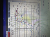
Second - the crossovers! I've plugged the T/S numbers in every free software I can find, and the a friend and coconspirator who has a Windows rig used Jeff Bagby's crossover designer as well, and I think I'm in the general ballpark but still not sure. I will post the FR of the drivers below, as well as the tweeter response with 5uF, 10uF, and 15uF caps on the tweeter (first order). Here are my questions about the crossover:

1. Frank declined to sell me his crossovers, and wouldn't give me the values, but we had a great conversation anyway, very good guy. Although he uses first order on both drivers, he said I might want to go second order on the tweeter. I would rather avoid an inductor on the tweeter mostly due to phase concerns, which is really high on my list and part of the reason I was originally going to use full-rangers. So first gate: first or second order?

2. With first order Butterworth, I've got pretty typical values at 1200hz, 1350hz, and 1500hz: 16.56uF/1.06mH(woofer), 14.72uF/.94mH, and 13.25uF/.85mH. Second order on the tweeter only lowers the cap values a bit and adds a small inductor.

As you will see in the frequency/impedance graph for these drivers, there's a really knotty issue due to a sharp impedance spike from the tweeter at just below 800hz, and this is really interfering with the falloff of the tweeeter and pushing up the FR almost all the way to the intended xover point (I'm using 1350 as a general target). I don't know how to remedy this, and am beyond reluctant to even go to 2nd order, let alone 4th. I'd rather start from scratch with a different driver, BUT this doesn't seem to bother Frank, he's got some way of dealing with the impedance that I don't understand. Zu audio is another example of a popular speaker using cheap Eminence drivers and squeezing out very good performance. I'm guessing these guys are manipulating the enclosures to make it all work?

Below I will post the following: The Radian EQ/Imp graph, and the tweeter response for first order using 4.7, 10, and 15uF values plugged into Jeff's program. Any and all guidance is much appreciated, and like I said earlier I'm willing to pay to learn here, I wish I had a mentor in my area but there is nobody doing this. Cheers, Bryan

I APOLOGIZE FOR THE LAST TWO IMAGES BEING ROTATED, I DON'T KNOW WHY THEY LOADED THAT WAY!

1685306092316.png


With 4.7uF cap, lower green line:

1685306143389.png


With 10uF cap:

1685306452490.png


15uF:
1685306637697.png

Attachments

  • 1685306319028.png
    1685306319028.png
    5.9 MB · Views: 109
  • Like
Reactions: Oabeieo

GE Tube Radio Restoration - Leaking Component

Hi guys 🙂
I just bought a General Electric tube radio for fifteen dollars at a thrift store. It was not in great condition and the electrical cord was cut off. I opened it up, and I saw that a component looked like it was leaking. Should I replace it before turning the radio on, and if I should, what is the name of the component? (It's the little component at the bottom left.0 Thx!
Photo on 5-29-23 at 5.49 PM.jpg

TPA3250 board - Switching PS - Noise Filter?

So I bought a TPA3250 board to check out. I picked up a MeanWell 24V 150w switching power supply to give it juice. I was buying connectors and associated doodads and threw a EMI filter into the bag, it's this one:

https://www.amazon.com/dp/B08D3MP48W?psc=1&ref=ppx_yo2ov_dt_b_product_details

Normally I'd buy the IEC connector + filter, but this stand alone unit caught my eye. And I figured I'd put it between the wall and the SMPS. But then I thought what if I put it between the SMPS and the amp board?

So I thought I'd ask those who know more than I: Would it be beneficial to have this sort of filter between the SMPS and the switching amp?
  • Does the filter care about the difference between DC and mains AC? (I think not?)
  • Is the MeanWell likely to be dirty enough up high to benefit from a filter like this? (MW is a good brand, but nothing is perfect)
  • is the 3250 board likely to care about a little HF power filtering? https://www.amazon.com/dp/B0B258YS3B?psc=1&ref=ppx_yo2ov_dt_b_product_details (maybe it makes enough of it's own noise internally, what's a little more?)

Thanks for your thoughts...

Resolved - Implemented Better notification - can't PM due to new member status

There is still some uncertainty with new members when they cannot PM. One example is when they sign up for Swap Meet and don't think to ask the seller to initiate the PM (not realising it is now presented in conversation form, and that they can indeed reply to them.) After discussions with member PRR, this suggestion has been put forward as one way to handle it.

I would add explaining the paging/mention system (@PRR ), the nature of the PM system and anything else that would help.
As a result of this, some post private details in public. I'm also concerned that some will needlessly give up.
PM-Newbie.gif
  • Like
Reactions: Jason

Lazy Singing Bush mono block build using THF51s

This will be a very lazy building thread as I take all the time, I need to have a fun build.
PCBs will come from ZM in version with many (most) components mounted.
PSUs has also been ordered. Those will be 65V SMPS's.

Chassis has also been ordered from Modushop and a big box was in front of my door when I came home this evening (26.5 kg).
What added to the weight was the special heat spreaders to spread heat from a single device on each side of the mono block chassis.
Each chassis has 2 x 200 mm heat sinks on each side. This gives a challenge when only one device is mounted that needs both sinks.
A couple of images attached. One image shows the unpacked 10mm thick heat spreaders. Two for each chassis.

DSC_3513_adj.jpg


DSC_3515.JPG


Shipment was only a few days.
Now time to think about how to mount the heat spreaders. Will have a closer look at the heat sinks to explore possibilities.
So far so good. This was the easy part just to order and spend some money!

Too low impedance at some frequencies

Hello,

I have a question that what will happen if the solid state amplifiers designed to drive 4-8 Ohms speakers face with 2 Ohms load at some frequencies?

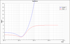
I'm building crossover networks, second-order low-pass filters, for my 4 Ohms subwoofers. Basically, I tried to simulate the results on simulator with the component values I already have; 3.3mH and 390uF pairs. The result is crossover point of 150Hz with Chevbychev alignment (+3dB at 150Hz).

However, the impedance curve fell down to 2 Ohms at 150 Hz, as depicted on attached. So, will any dangers happen to the amplifier?

Attachments

  • 2023_05_31_10_07_36_Window.png
    2023_05_31_10_07_36_Window.png
    5.7 KB · Views: 88

SB Acoustics has some interesting marketing tactics, I can't tell if they're geniuses or morons

SB-acoustics-sb23cacs45-8:


Why Ceramic?
Ceramic cones offer smoothness and harmonic richness unavailable from conventional paper cone material. Ceramic materials also offer significantly higher stiffness numbers and slightly better internal losses than typical metals such as titanium or aluminum. Compared to polymers, paper, and other soft materials, ceramics provide:
  • Significantly higher stiffness to weight ratio.
  • More consistent performance over a wide range of temperature and humidity. For example, polypropylene's performance changes dramatically with temperature, while paper can be significantly affected by humidity.
  • Superior immunity to UV light and sunlight.
  • Superior immunity to water and salt water.
  • Superior immunity to combustibility

They're highest "satori" line Satori-wo24p-8:

FEATURES
  • Hard paper cone for improved piston operation (made in-house)


\I guess that "marketing" makes sense since I've never heard people complain more about the sound a premium line of woofers more than the Satori line. Low BL, high mms, low compliance suspension; what do you want, but still?

John "Zaph" (the great) Krutke stated -- "The 7" Satori probably has the best performing motor in the business, as shown by the class leading harmonic distortion plots." -- http://zaphaudio.com/blog.html --
Okay, got it Zaph the great. AND this is the smartest guy in audio in the USA.
When I walk around and observe my surroundings it's all starting to make sense now.

Is it possible to make det best sounding speaker in the world using only Monacor SP-13/4? Let's find out!

Have a pair of sp-13/4, that was suppose to be used in another project. That project went another direction.
I therefore have a pair of sp-13/4 that i can use to i want. And i want to find out how good sound it's possible
to get out of them.


I dislike following rules and plans. Because it doesn't teach me much.
So the philosophy of this is project is to test out every idea, and measure if it works or not.
There is no right and wrong answer. So don't hesitate to come with ideas.

In a couple of week my nvidia p40's will arrive, to use machine learning is an option.
Got a basement full of old wood parts. The only limit is our mind.

My first idea to test is to see if i can use my coumpter desk as part of a horn.

Attachments

  • Screenshot_2023-05-26_18-27-02.png
    Screenshot_2023-05-26_18-27-02.png
    297 KB · Views: 238
  • Screenshot_2023-05-26_18-26-44.png
    Screenshot_2023-05-26_18-26-44.png
    292.3 KB · Views: 252
  • Like
Reactions: AllenB and GM

Autotech JMLC horn 350hz

For Sale: In the UK (will ship to Europe)


Autotech JMLC 350hz horns X2 in white.

Has 2 throat sizes: Horn throat is 2", but a pair of 3D printed black PLA throat adapters are included to mount a 1.5 or 1.4 inch (zero degree exit angle) driver on. The adapters are JMLC profile and an exact fit.

Excellent condition horns, amazing auto paint job.

Open cell throat foam 'bungs' cut to size are also included. (improve response further)

Was mounted to a pair of JBL 2452SL drivers (zero degree exit angle)

Phenomenal mid range sound on voices. Can be heard running.

Shared album - lance bartlett - Google Photos

Shared album - lance bartlett - Google Photos

Shared album - lance bartlett - Google Photos

Shared album - lance bartlett - Google Photos

Shared album - lance bartlett - Google Photos

https://photos.app.goo.gl/JZkpgLEgyLwtc5FH7

The adapters cost £400 alone, and high density PLA (strong) professional prints.

The horns were £800 for the pair.

Does not include the JBL drivers (can negotiate this for the right price)

£650 obo for both horns and adapters.
  • Like
Reactions: Pano

Looking for some advice on small fanless PC for music server

Hi,

My ancient PC that I was using to stream music finally gave up the ghost. I am looking to replace it with a low cost mini PC. I play full res using Foobar, and stream Spotify. I am looking for a drop in solution using windows and will use a small 8 inch monitor for navigation. I've seen several options on Amazon under ~ 150 bucks. Does anyone have some recommendations ?

Thanks

Can't insert link when editing recent post

Created and posted into a thread. Decided I wanted to add to post, so edited it put my text in and wanted to add a link to an external site (Bandcamp) selected some text, got the link dialog up, pasted the link and the edit was saved straightaway without the link when I pressed insert on the link dialog.

This was on Windows 11 with Chrome 113.0.5672.127 64 bit

This post

For Sale F5X Amplifier

A fully assembled F5X amplifier as described in this thread: https://www.diyaudio.com/community/threads/f5x-the-euvl-approach.183362/page-45#post-6398493

The amplifier is dual mono with regulated power supply and protection board. It has 105C capacitors in the power supply. It works with 230V supply.

Price 2000 euros or best offer, shipped from Vienna (Austria)


IMG_8915.jpeg
IMG_8917.jpeg
  • Like
Reactions: d to the g

Uriah Dailey LDR pickle

Hello .
I have some trouble with a lightspeed attenuator.
I bought a unasembled ldr kit, with all parts but no schematic.
I found a Uriah Dailey pdf on a ldr attenuator and thought all was good, but it turns out my boards are not the same, pdf board is a stereo board, mine are dual mono, the regulator boards, there are no silk screen markings showing part values, only part numbers. See pic.
I cross my fingers that one of you great diyers have some documentation. Or schematic of his stereo board.
20230526_152747.jpg

What is this device in STAX headphone?

I have an old STAX Lambda Nova Signature made in 1995. I enjoy using it very much with a home made tube amplifier. It is old and some parts were damaged, but I have DIY repaired them as far as I could. I found one device in the bias circuit (pointed by an arrow in the photo). It looks lika a SMD resistor just attached with the electrostatic sound element. If so, it may separate the bias circuit effectively between channels. I tried to measure its resistance using a digital multimeter, but it showed out of range. I appreciate it very much if anyone kindly tell me about this device. If it is a SMD resistor as I guess, how much is the resistance? It will be very helful, because I am planning to build a ESL headphone by myself!
STAX_bias_device_small.jpg

Transistor amplifier advice

I have been restoring an old integrated amplifier.

Diagram.jpg

I found various problems which have now been remedied, and I have replaced all the electrolytic capacitors, transistors, and both ICs.

I think that I have finally got the bias set correctly, although it seems to be a very delicate balance between distortion and running very hot indeed.

It sounds very good with CD as source through either Tape or Radio input, but output is very low when used with the MM input. I have tried a few different cartridges with no noticeable difference, and I know that CD output is always much higher than MM (and probably higher than tape or tuner outputs when the amp was made) Since it is not very powerful, but still sounds very good with a high level CD signal, my question is: can anything be done to modify the MM input circuit to increase the gain? I am not sufficiently knowledgeable to be able to understand the circuit, but I am able to use a soldering iron and DMM, and I would rather modify (if possible) the circuit than use a separate phono stage, and use it principally for playing records not CDs.

I would be very grateful for any advice!

Audiostatic ES-100 Schematics

Can you advise me? I'm planning to build a replica of ES-100, but I can't find a complete wiring diagram and information about transformers. There is some information in a book, but I'm looking for something like what's in this link. Thank you.
https://www.quadesl.com/pdf/es50_schem.pdf

If anyone has photos of your construction or the remaining 6-micron film, I would be interested in purchasing them. PS: Please don't message me about the Facebook page, as I'm already aware of it, but it's not an efficient platform for finding what I need. The forum is more suitable for this purpose.

Testing thread only - Ignore Function - not for general discussion

General discussion here - https://www.diyaudio.com/community/threads/ignore-functionality-not-working-well.383381/

@PRR @abraxalito and others interested in testing the ignore function, quoting, linking and other things... devise your tests and disclose them here. I will set them up with a testing account.

You can ignore/unignore and discuss the testing account without fear of offending the member on the other side of it.

Crossover point decision help needed

I decided to add the subwoofers to the existing 2-way speakers. However, I will only apply low-pass filters to the subs and no hi-pass filters to the mains. I believe this design is a 2.5-way system, thus I've posted this thread to the Multi-Way forum.

Anyway, I have two 3.3mH inductors and two 80uF and 390uF capacitor pairs.

From online calculator, I could form two second-order low-pass filter combinations as follows:

A) 3.3mH + 80uF = 300Hz, Bessel alignment
B) 3.3mH + 390uF = 150Hz, Chevbychev alignment (with +3dB at 150Hz)

According to what I've read on the forum, some people believe bass begins to count below 400Hz, thus, option A) be sufficient. However, some individuals believe that the subwoofer should be switched off as low as feasible, therefore option B) may be preferable.

Overall, which choice should I choose?

A convolution based alternative to electrical loudspeaker correction networks

The combination of full range drivers and convolution based correction can potentially make for a system which is simple and well behaved from both a frequency and time domain perspective. The provided guide however, will help anyone improve the sound of their system, regardless of their chosen loudspeaker type, using free software and a minimum of hardware. This guide assumes the use of a PC as the source, however, it is possible to hear the potential improvements afforded by this method by preprocessing music tracks with correction filters and burning to a CD.

Dropbox - Room Correction.zip

After downloading and unzipping the attached file, you will find a text guide to get you on your way. This guide is not meant to be a substitute for the instruction manuals of the software programs that will be used, but I have tried to articulate the steps in a manner that might be understandable to someone for whom these processes are unfamiliar.

A good starting point with the standard configurations might be "minimal.drc" with the following edits: PTType = N, and PSPointsFile = BK-2-44.1.txt (this file must be copied from drc-3.2.2/source/target/44.1 kHz to drc-3.2.2/sample). This will give modest correction strength and a traditional "tilted" target frequency response.


Dropbox - Psycho Filter.zip

From the PsychoFilter "readme" file:

This correction method uses two passes through DRC per channel (necessitating the use of two configuration files). During the first pass (prefiltering), the excess phase portion of the impulse response is removed, the remaining (minimum phase) portion is windowed with a frequency dependent length of approximately 3.6 cycles (1/5th octave resolution), and mic calibration is applied. During the second pass, the spectral envelope of the prefiltered impulse response is calculated with Bark scale resolution, inverted, and a target frequency response is applied.
  • Like
Reactions: Freedom666

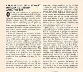
Lafayette KT-250-A

Hi!!!
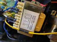
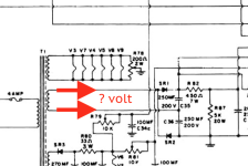
Tell me how much volt does this winding of the transformer have? How many volts is there? alternating current
I want to order a power transformer need data!
How many volts? How much ampere?

Attachments

  • lafayette_kt-250-a_kit_amplifier_sch 2.pdf
    lafayette_kt-250-a_kit_amplifier_sch 2.pdf
    463.7 KB · Views: 122
  • Снимок экрана 2023-05-28 в 14.10.30.png
    Снимок экрана 2023-05-28 в 14.10.30.png
    157.6 KB · Views: 126
  • Снимок экрана 2023-05-27 в 21.03.37.png
    Снимок экрана 2023-05-27 в 21.03.37.png
    1.5 MB · Views: 118
  • Снимок экрана 2023-05-27 в 21.05.44.png
    Снимок экрана 2023-05-27 в 21.05.44.png
    753.5 KB · Views: 123

PA System with Two-way radio

I am running a Soap Box Derby race and I saw an announcement system at another race I wanted to duplicate. They used horn speakers connected to a walkie talkie. This allowed a separate walkie talkie to be used as a "microphone". This is an outdoor event and the system is used to announce which racers are on the hill and also times of each heat. We have a small portable speaker with a microphone and it can only be heard by those within 50 ft or so. Any idea how something like that would work and what equipment I need? Or how I might hook additional speakers to the current sound system and run them via wire to other parts of the venue.
Thanks in advance

Yamaha RX-V365 questions

Hi there,

I just bought a used Yamaha RX-V365, now I'm waiting for it to arrive, I mean it might arrive all broken and it would be all pointless but I'm already going to ask ahead...

1- I would like to know if it's possible to add 7.1 to it like using the front B channel as the extra channel needed for surround and like hack the FW so that the 5.1 analog inputs work and show as 7.1 and add the extra 2 needed coaxial inputs?

2- Also want to know if it's easy to add 5.1/7.1 preout ports to the rear?

3- I would like to know if it would be bad to replace the most likely dried thermal crap including the mica protection or whatever it's used on this receiver and use PC high performance thermal pads directly in the transistors to the cooler and like 1mm thick (I'm talking about those more expensive thermal pads with actually good thermal transference of like between 10 to 14 W/MK and they are non electrically conductive and there's also soft versions...).

4- I'm also considering to add a PC fan of 12V, what would be the best place to solder one so that it goes ON when power is ON and OFF when OFF but need around 12V.

Thank You,
guily

Sonus Faber Extrema Drivers & Xover

I love my Extrema speakers so much I bought a full set of replacement drivers and cross-overs from Sumiko in 2012 in case anything ever went wrong... it didn't and now I'm selling the Extremas, so it's time for these parts to go. They are all in boxes originally shipped to me, opened only to inspect but never taken out or used. Full set includes Dynaudio’s Esotar 330T/SF: a 28mm soft dome that was rightly regarded as one of the best around at the time; the mid/bass drivers are 19cm Audio Technology Flex Units; the passive radiators are (I assume) TDL 3020GT03 (since the B139 was no longer made by that time). Also included are SF crossovers for the Extremas. The full set cost $4,880 from Sumiko at the time - asking $2,900. Would prefer local pickup (Westchester County, NY) - will include UPS Ground Shipping in the US only. Paypal F to F or pickup yourself with cash only. Email with questions.
  • Like
Reactions: matsurus

The art of upgrading Vintage front speakers

Hi, I'm a newbie to this site. Am the happy owner of a vintage (2005) pair of B&W 802Ds. I like the sound driven through highly upgraded HOLFI PRE 1,5,1 and NB250 (By Peter Holstein) battery-driven amps. However, the speaker set needs new life - and even though I like the analytic part of the music stage the Midrange and tweeter do not quite work for me these days. It's too much 'in your face' sound. Am in the process of upgrading the core crossover components to much better quality (Jantzen Caps etc) that and a possible rewiring internally and adding impedance checking components will def. be an improvement. Also soldering the wire to the driver connections will add to the quality, changing the binding posts to WBT and Tube connectors (using the Bi-wiring double set) will work. However, I do believe that redesigning the whole crossover would be the ultimate challenge. Believe there was one post on this forum where that was done taking hours of work - if anyone has any experience with a new design of the crossover I would be interested to learn from that - By default, I'll go the changing to better components (Caps and coils in particular)..

If anyone is interested, there's a random drawing for a Marantz CD 60 ($999)

https://futureaudiophile.com/audiophile-sweepstakes/

I have nothing to do with this, and I think that Stereophile has been doing equipment give-aways too.

I don't think my posting this just for everyone's information offends the rules; but if a Moderator thinks otherwise, that will be that.

"Future Audiophile" wants people to answer survey questions (such as how many CDs do you own), and of course they want FB friends and newsletter subs.

They will randomly draw a winner from those who complete the survey.

My view is, the odds are probably a little better than Powerball!!!

The entry period ends May 31, with the random drawing in early June.

Best of luck,

john

(FA published my article on a retrospective look back at the Ralston Listening Room at the University of the South in Sewanee, TN, so I will not be entering.)

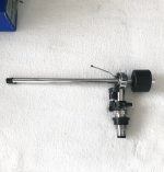
Can someone identify this tonearm ?

Per tittle can someone help identifying this tonearm please ?
This one in the picture came from an Leak Truspeed turntable (for sale on ebay) but asking because I bought a Sugden Connoisseur BD2 and it as the same one and I know that the vintage Sugden BD1 and 2 normally were fitted with a Sau 2 or 4 tonearm.
Anyone ?

PS: I tried a google picture search and no luck.

Attachments

  • braco305.png
    braco305.png
    192.9 KB · Views: 143

Expanding Stage Monitors

I have a Peavey 400 SC - 6 channel power mixer with two power amp outputs: one for MAIN and one for MONITOR. Each supplies two 1/4” jacks to go to speakers. According to the manual, if I have 8 ohm impedance monitors the max I can use would be two, resulting in a net of 4 ohms. I really need 4 monitor speakers on stage. Is there a way I can expand and still use the power mixer?

JBL 2235 in Onken

Help in fitting JBL 2235 spec into Onken Calculator NL. At first attempt with spec. sheet in hand and Onken Calculator waiting for input my first try was a success. The Bv. was 300-ltrs and F3 a respectable 40Hz. I may have made an error inputting data back when I first got these 2235 speakers/woofers cause now still with spec. sheet in hand from JBL Heritage download Box Volume is 3324-ltrs. What happened? I managed to get the calculator to remain steady at 300-ltrs but either the port is too long, or too short or port too small or too slots are not realistic size to the front dimension! Can this design be over-ridden to still have a good response?

Suggestions for cap replacement on my MiniDSP 2x8

Hi:

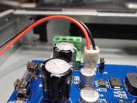
Audio newbie here, and little to no understanding of electronics. I can solder. I do know that one of the large eletrolytic caps in my MiniDSP 2x8 is bulging. It's one of a pair, so obviously I might as well replace both.

Can someone tell me what purpose these caps serve and whether they are in the audio path or not? They're 3300uF and the brand name appears to be ChangX. If I'm correct about that, aren't those renowned for being of poor quality/reliability?

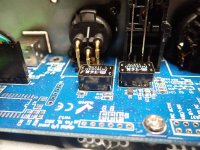
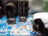
Also, what are the black flat-ish rectangular components in the next pics labelled "m-tek d4101dag"? Google searches seem to suggest they're voltage regulators? If so, is there ever any tiny variation on how flat the tops should be? Because two of them seem to almost completely flat on top, but not as flat as the other two. If I'm replacing components, I only want to do it once if something might be flaky. Does anyone know if those rectangular things are through-hole or surface mount? I'm pretty decent at soldering, but couldn't do SMT if my life depended on it.

Thanks

Attachments

  • Image00311.jpg
    Image00311.jpg
    326.6 KB · Views: 214
  • Image00111.jpg
    Image00111.jpg
    349.6 KB · Views: 209
  • Image00511.jpg
    Image00511.jpg
    482.4 KB · Views: 217
  • Image00611.jpg
    Image00611.jpg
    450.9 KB · Views: 231

MA Audio HK-4000D

Working on this monster which is not making enough rail voltage (+/-11vDC). Pulse drive on the PS fets is very weak. The amp only draws 0.3A from the bench, but most of that is likely from the FAN, display board, and a few LEDs.

TL494
1. 0.002
2. 3.113
3. 3.740
4. 0.058
5. 1.483
6. 3.405
7. 0
8. 14.22
9. 0.014
10. 0
11. 14.2
12. 13.04
13. 4.96
14. 4.96
15. 1.991
16. -0.453 (YES, Negative)

R76 and R77 are missing. Do you know the value of these two resistors?

INA1650 : What happens if I do NOT connect signal ground to chassis ground?

Hi all.

I'm making line receiver circuit using INA1650 and signal relay, which can receive both differential and single-ended line inputs.
This circuit's main goal is converting differential/single-ended line input to single-ended line output, suppressing common mode noise and forms suitable signal to use amplifier input.

Using relays gives ability to the circuit to selecting input source by using 1 INA1650 chip, whatever it's differential or SE(SE signal also treated as differential using 4 signal path).
Making this circuit can be possible to me thanks to Ti's INA165x datasheets, which kindly suggests both differential and SE input scenario at Typical Application(Figure 58, 59, 61).


1.PNG

2.PNG

3.PNG


But I got a problem.

Seeing the Figure 58 and 59, those application input source should only be connected to the chassis ground, which shares same ground plane between every input sources whatever it is selected to use or not.
The Ti's datasheets also describes the Figure 59 as 'Floating Single-Ended Input', that means the chassis ground and signal ground must be isolated. Am I right?
Seems nothing problem here.


But... The main problem is Figure 61.

3.PNG


In Figure 61, in TRS audio interfaces, the input source's sleeve should be connected to chassis ground and also SIGNAL ground. Wait... what?

At first I mentioned, I will gonna mix those above three circuits in one.
Figure 58 and 59 is okay. Those inputs should be connected to only chassis ground and can be isolated from the signal ground.
But if I also following Figure 61 and connecting both chassis ground and signal ground, Isolated chassis and signal ground at Fig. 58 and 59 gonna be useless!

I'm really concerned about sharing chassis ground and signal ground can cause any potential danger, just like electrical shocking or audible noise or harm to any other chip, etc.

So I'm considering about NO connecting signal ground at Figure 61's TRS input source.

If I do not connect signal ground at TRS input, what will happen?
No sound will play when selecting TRS channel? or more huge problem can be happens?

Thanks for reading, and I will hope for any suggestion.

EqulizerAPO Crossover filter BU1/LR4 Does anyone know abut this?

1674139587.png


I found this value from REW website.
I understand about LR4 filter. If i want LR4 Lowpass, If applied double, it was LR4.
LowPass 90hz Q 0.707

However, there is no information about BU1. Does anyone have any information about this? I was able to make a Bu1 filter with a fir filter in the Release, but I want to make the most of the functions in the Equalizer APO.
(Btw, The reason why I do this is that I have to make it manually because EQ APO does not apply even if I apply crossover LR, BU, etc. from REW and export it to Txt.)

TubeLab SSE Available

EDIT: this has been claimed!

I have a Tubelab SSE that I built a couple years ago I’d be willing to send it to anyone looking for a project just for the shipping cost.

Works and sounds great. Volume pot is bypassed and the three switches on top are not connected so it only operates in one mode as a power amp but it has potential. The transformers alone would likely be worth the shipping. It weighs about 40 lbs and I’d probably ship the board and tubes separate from the chassis.

Any questions just ask I can provide a parts list of need be. PM me if interested.

IMG_6278.jpeg

How to make a DIY subwoofer project that includes both the speaker and the electronics for it

I need to build an active subwoofer, that can be connected to a Sony 5.1 receiver, using an 8" in a closed box. I want a small box, that's why I'm not using a 10" or 12" woofer.

As the bass reach down of the speaker I'm considering using (Dayton Audio RS225-8 8" Reference Woofer) is -15dB @ 30Hz, I am investigating using DSP to correct that to -3dB if it's possible.

https://www.parts-express.com/pedocs/specs/295-356--rs225-8-spec-sheet.pdf

I plan to use the subwoofer RCA output to link the DSP. This the one I'm planning to use.

https://www.parts-express.com/Dayto...utm_medium=Impact&utm_campaign=Impact&irgwc=1

So anyone that did something similar or used this DSP, please do jump in and comment.

help! -- newly built Elekit TU-8500 preamp not powering on

Hi -- I just finished building an Elekit TU-8500 preamp and it won't power on. I've built two ACA's which both worked on the first try but am otherwise a noob to DIY electronics. I'm not sure how to check to make sure if I've hooked up the power supply correctly or if it's working and if the problem lies elsewhere. Can anyone help me debug what's going on? I have a multimeter but not much else in the way of tools beside the usual mechanical ones. Thanks!

100 - 600 Hz midbass horn design questions

is it possible to cleanly cover 100 - 600 hz with an FLH that has approx a 26"w x 24"h mouth and less than 30" depth?

I'm running this in conjunction with Yuichi A290 clones and B&C DCX50 coax drivers, so its being designed for higher end home audio use.

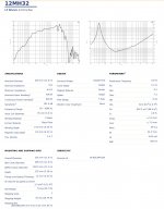
Midbass driver is the B&C12MH32, which should be a good choice for this purpose based on TS data and specs. I already have this driver on hand.

Looking on the web, I see some designs by Edgar with his System 100 horn using a 15" JBL. Also some other designs which are far too big to fit where I need this to go, specifically being able to physically time align the whole thing. The Inlow designs are nice, but again too deep. I understand there will be tradeoffs with truncated flares. Hopefully there is an existing design out there which is close to what I'm looking for.

I'm not that experienced with midbass horn design from scratch. Other than repurposing existing designs by modifying the throat or rear chamber, its not something I'd tackle. I've used Hornresp to explore some other bass horn designs, but currently don't have access to it due to ongoing PC issues. If someone experienced in this area could maybe plug in a few numbers and point me in the right direction, I'd greatly appreciate it.

Attachments

  • 20221102_050533.jpg
    20221102_050533.jpg
    247.9 KB · Views: 305

Swapping out JRC 4558DDs

To start I am very new to this, as in no experience whatsoever. The gist is: I want to swap out the jrc 4558dd on the over drive channel of my Marshall mg100dfx for the lm308. My thinking is it will make it sound like the pro co rat. Thanks. Please tell me if this is stupid, or if there’s a way to execute on the idea.

Attachments

  • IMG_6956.jpeg
    IMG_6956.jpeg
    251.3 KB · Views: 118

Recommend DIY build learning resources?

Hello!

Can anyone point me to some reading material that will assist me in learning about how to DIY audio electronics?

Some background:
I've decided I'd like to build a tube preamp. Specifically this: https://www.cascadetubes.com/the-12au7-cathode-follower-color-preamp/
This will be my first attempt at a project like this. I'm an electrician, so I know my ohms law and electrical safety, and I can solder and read the circuit diagrams just fine. I could no doubt fumble through this and be A-OK.
But..
I'd like a deeper understanding.
The language used online to describe these circuits is foreign to me. Presumably because the majority of you are American/European, and I'm from Australia, or maybe it's just because it's a different field, but B+ voltage for example is a term I'd not heard before looking into this. Does that just refer to the active (positive) side of the circuit or is there more to it?
Also, I look at that circuit linked above and ask myself 'OK but WHY does that capacitor connect to earth (ground), at that point in the circuit? What is the intended effect on the audio?'

I could continue detailing my ignorance, but essentially, I just want to know more on the subject.
Any resources you can point me to?

Thanks so much!

SimAudio Amp 100nF caps and Load Resistors?

Hey Gents, looking at a SimAudio amp, I noticed a few things - 1, what I gather are two load reisitors between the binding posts - are there any benefits to getting rid of those or is it best to leave them, maintain impedence? I heard of instances where removing these open up the sound considerably.

Also, on the amp boards there are 100nF caps across the terminals on the underside of the board on 2 of the larger 1200uF caps - what exactly are the purpose of these, filter? If I remove them while replacing the aged caps would I gain any change in tone?

For Sale NOS Tung-sol 5881 Made in USA

SOLD
These are original NOS Made in USA Tung-sol 5881. All have the same manufacturing lot code 322DZ3. All tested good on Hickok 539B. I have these for a long time and is now clearing out my tube collection. $250 for all 5 tubes including Paypal fees and shipping to contiguous US states.
Below are measurement done on a Hickok 539B. They all are fairly close and I would say that they are within 10% of each other. Do note that ideally, tube should be matched at their operating point specific to your application. However, this gives you an idea that they are within the same range.
tube#Vpg (V)Ip (mA)umhos
1140344400
2140354600
3140354500
4140354800
5140344400

Vpg is grid to plate voltage. All measurement was done after 10 minutes of warm up on the tester.
TungSol5881-1.jpeg
Tungsol5881-2.jpeg

Xs6600 Emitter resistors

I'm going through the resistors in my Xs6600 and noticed the emitter resistors on my right sub channel are different than all other emitter resistors in the amp.

The left sub channel matches the rest of the channel's (4, .22-Ohm resistors)

Left sub channel
20230518_114621.jpg


However the right sub channel has different value resistors (4, 2.0 resistors)

20230518_114640.jpg


I am wondering if this is normal?

Can't figure out subwoofer tuning

Hi all!

I have 2 B&C 18PZB46 and 2 B&C 18PS46 woofers.
They're all in identical 185L sub boxes. (185L without the woofer, is that the correct figure to use?)
Right now all these boxes are tuned to about 50Hz,
However they don't sound as great and get as loud as I'd hope

Is there anything I can do to the tuning frequency to help with some of my problems? Any other solutions are appreciated as well of course!
I'd rather sacrifice some sound quality and have them be a bit louder, than the other way around. Some distortion isn't THAT big of a deal.

I've also added the WinISD calculations I've done, but I'm not completely sure if they are correct, since I'm not too experienced

Thanks in advance!
-Daan

Datasheets
18PZB46: https://www.bcspeakers.com/media/W1siZiIsIjIwMTMvMDMvMTEvMTUvNTIvMzAvNTQyL2ZpbGUiXV0
18PS46: https://www.bcspeakers.com/media/W1siZiIsIjIwMTMvMDMvMTEvMTUvNTIvMjYvMTE2L2ZpbGUiXV0

Attachments

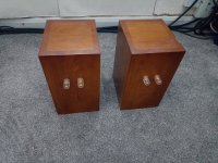
Mark Audio CHR-70 V2 in wooden boxes (UK)

Now sold.

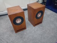
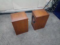
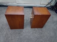
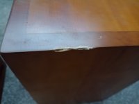
Full range drivers in wooden bass reflex boxes. Some damage to the top of one box (picture). Drivers undamaged and working fine. £40 will post for an additional £10 or collect from Warrington WA4.

Sold

Attachments

  • IMG_20230529_150850151.jpg
    IMG_20230529_150850151.jpg
    533.3 KB · Views: 93
  • IMG_20230529_150859289.jpg
    IMG_20230529_150859289.jpg
    390.2 KB · Views: 98
  • IMG_20230529_150907262.jpg
    IMG_20230529_150907262.jpg
    604.3 KB · Views: 92
  • IMG_20230529_150915908.jpg
    IMG_20230529_150915908.jpg
    612.1 KB · Views: 96
  • IMG_20230529_150920574.jpg
    IMG_20230529_150920574.jpg
    187.5 KB · Views: 96

Woofer for a 3 ways...

Hello,

I have a two-way bass reflex with 6"+1" Peerless drivers and I'm wondering to add a woofer or a sub and cross it about on 200/300hz. Also, I'm looking for some new project, starting with a 2 ways KIT. I can measure and use ARTA (if I remember how to do...) but I'm not so skilled in electronic so I prefer to start with a two-way KIT and add a woofer on my own.

So, the woofer I'm looking for, will first play with my Peerles mid/tw and then maybe... with new Satori or Scan mid-woofer.
What I am looking for is a good 10" woofer for sealed enclosure of max 40/50 litres (1,7cu ft), it would be active with 250W amp and DSP, it has to go up, say, to 500hz. I don't need deeeeep bass and high SPL, just 40hz with good transients and the ability to blend well with a 5" or 6" mid. As I use an active amp ... sensibility is not the main problem, I think.
I'm trying to simulate some Wavecor, WF275BD01 seems to be good but F3 is about 50Hz, if I find something that goes deeper is better. There is also Wavecor SW223BD02s (and SW270WA01)but I don't know if they reproduce well mid-bass frequencies, an what about CSS SDX10 ?

Any advices?

Thanks!

For Sale huge tubes and related parts estate sale JUN 17-18 Irving TX

The gentleman was a prolific experimenter and builder. This is his 'stash' and occupied over 500 sq ft in the home. There is also two sheds to explore. It'll be worth it to go. There are hundreds of transmitting, receving, and power tubes, plus all the other parts needed to build a wide variety of tube gear, and also some solid state items. Please see flyer, which is also online at https://www.bunkerofdoom.com/brady_estate.pdf

This is not mine. Please do not ask me about specific items etc. I am merely helping our DIY group by posting this for the benefit of local members. Note one thing please; their flyer says it all has to go and will be priced to please.

I do not consider this a commercial post at all. Their concern is that all these tubes and parts etc. will be pitched out in this age of smartphones and instant gratification.

Attachments

Projects by fanatics, for fanatics
Get answers and advice for everyone wanting to learn the art of audio.
Join the Community
507,708
Members
7,885,237
Messages

Filter

Forum Statistics

Threads
406,084
Messages
7,885,237
Members
507,708
Latest member
ahmadmusowwir