Hello everyone!
It's been a while since I've been lurking on diyAudio, observing what's going on. I'm glad I finally have a good reason to post!
I moved from France to Canada and had to leave my pair of Atlantis Lab behind. Immediately, the idea of getting a new pair while waiting for the other one to arrive from overseas sparked my desire to build one myself for the first time.
Objective
My goal is to build a pair of studio monitors for
sound editing and mixing. It's obvious to this knowledgeable community that it's an ambitious project, especially considering my first constraint. Nonetheless, it remains the guiding principle and the purpose for which I will ultimately use them.
Before we continue, I want to emphasize that
I am fully aware that what I am about to present is merely a projection. None of what is established here will definitively tell me how these speakers will actually sound. However, one has to start somewhere, and it's best to start off in the right direction.
Constraints
As mentioned in the introduction, this is my first DIY design project. I've learned a lot during these initial design phases that led me to post this thread, and I know I'll learn even more once I get my hands dirty. The first constraint is the
price. I don't want to break the bank by making mistakes (especially correcting them) on my first project.
The second constraint is the
size. I want to be able to place these monitors on a desk or on stands, in a near-field setup.
The last constraint, closely related to the objective, is the
linearity in the speakers' response.
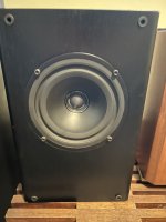
Used Transducers
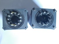
I came across the
Visaton WS17E and
Visaton SC10N on
Solen.ca while browsing the site in search of the ideal combination for a beginner. The price constraint made me consider Dayton Audio for a long time. However, the Visaton speakers caught my curiosity, and it took me longer than I care to admit to ask the relevant question: Is there already a documented project using them?
Without further suspense, Visaton themselves propose the
CLOU design.
You'll see that this project only shares the transducers and part of the enclosure with the original CLOU design. I'm not sure yet if that's a good thing.
Crossover
From the start, I know that the linearity constraint will be difficult to meet. But we’ll do what we can.
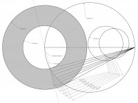
I'm using VituixCAD. The amplitude and impedance response curves were obtained using FDGraphTracer from the speaker specsheets provided by Visaton. I started by recreating the network presented for CLOU, but the resulting crossover was far from satisfactory.
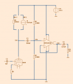
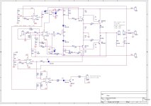
CLOU original cross-over network
CLOU resulting SPL response
I went back and forth with FDGraphTracer multiple times, double-checking the value and placement of the components to ensure it wasn't an error. So, I made the decision to design it from scratch.
I began by adding a source-side resistor to compensate for the sensitivity difference between the two transducers.
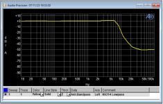
It quickly became evident that a first-order filter would not be sufficient for either of the transducers.
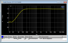
To my surprise, a second-order high-pass and low-pass filter was enough to achieve what appears to be an acceptable response. You'll notice that I had to reverse the polarity of the tweeter to achieve this result.
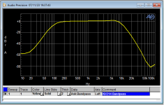
The Total SPL graph shows a curve of ±3dB between 60 Hz and 17000 Hz (78.2dB ~ 81.7dB).
Project cross-over network
Project Total SPL, separate SPL and Normal Phase
Project transfer functions
Project group delay and separate phase
Project load impedance
Project null reverse with tweeter polarity switched
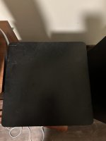
Box
The original CLOU design is a tower speaker with two woofers. One woofer is placed in a sealed box near the tweeter, while the other is separated in a larger box that serves as the base of the speaker. This larger box, below the sealed one, has a hole near the base. I'm unsure if it's a simple hole, a port location, or a cutout for the terminal.
My design eliminates the lower portion, including one of the woofers, and only retains the sealed box. Using 16mm panels, the same as CLOU, the external dimensions are 220mm W x 331mm H x 320mm D, with an approximate volume of 16100cm³, excluding the space occupied by the speakers, shelf bracing, and other components.
An absorbing material will also be added. I will determine the quantity during actual measurements.
VituixCAD's enclosure design tool calculates, for a box of this volume and this woofer, a curve with a resonance of +2.5dB at 80 Hz.
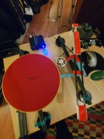
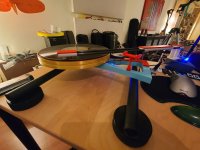
SketchUp preview of the box
Box projected response
Conclusion
We've reached the end of the project presentation. I'm genuinely eager to receive your feedback. Please feel free to ask questions and share any remarks or comments.
While I enjoyed the process to get here after many explorations with other speakers and box types, I'm still uncertain about the robustness of these plans.
Some questions I currently have are:
- I have a network in stock that includes a baffle step corrector. Is it wise to consider integrating it at this stage of the design?
- I'm concerned about the load impedance curve. Should I incorporate an impedance corrector into the network?
- I haven't considered any Z-axis offset. Is it worth it to add a ladder delay network?
- Should I be worried about the box resonance anticipated by the software? If so, what should I consider doing? Install a Variovent to virtualy add volume to the box?