Hello everyone!
It's been a while since I've been lurking on diyAudio, observing what's going on. I'm glad I finally have a good reason to post!
I moved from France to Canada and had to leave my pair of Atlantis Lab behind. Immediately, the idea of getting a new pair while waiting for the other one to arrive from overseas sparked my desire to build one myself for the first time.
My goal is to build a pair of studio monitors for sound editing and mixing. It's obvious to this knowledgeable community that it's an ambitious project, especially considering my first constraint. Nonetheless, it remains the guiding principle and the purpose for which I will ultimately use them.
Before we continue, I want to emphasize that I am fully aware that what I am about to present is merely a projection. None of what is established here will definitively tell me how these speakers will actually sound. However, one has to start somewhere, and it's best to start off in the right direction.
As mentioned in the introduction, this is my first DIY design project. I've learned a lot during these initial design phases that led me to post this thread, and I know I'll learn even more once I get my hands dirty. The first constraint is the price. I don't want to break the bank by making mistakes (especially correcting them) on my first project.
The second constraint is the size. I want to be able to place these monitors on a desk or on stands, in a near-field setup.
The last constraint, closely related to the objective, is the linearity in the speakers' response.
I came across the Visaton WS17E and Visaton SC10N on Solen.ca while browsing the site in search of the ideal combination for a beginner. The price constraint made me consider Dayton Audio for a long time. However, the Visaton speakers caught my curiosity, and it took me longer than I care to admit to ask the relevant question: Is there already a documented project using them?
Without further suspense, Visaton themselves propose the CLOU design.
You'll see that this project only shares the transducers and part of the enclosure with the original CLOU design. I'm not sure yet if that's a good thing.
From the start, I know that the linearity constraint will be difficult to meet. But we’ll do what we can.
I'm using VituixCAD. The amplitude and impedance response curves were obtained using FDGraphTracer from the speaker specsheets provided by Visaton. I started by recreating the network presented for CLOU, but the resulting crossover was far from satisfactory.
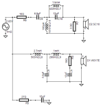
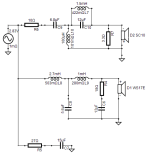
CLOU original cross-over network

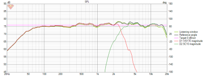
CLOU resulting SPL response

I went back and forth with FDGraphTracer multiple times, double-checking the value and placement of the components to ensure it wasn't an error. So, I made the decision to design it from scratch.
I began by adding a source-side resistor to compensate for the sensitivity difference between the two transducers.
It quickly became evident that a first-order filter would not be sufficient for either of the transducers.
To my surprise, a second-order high-pass and low-pass filter was enough to achieve what appears to be an acceptable response. You'll notice that I had to reverse the polarity of the tweeter to achieve this result.
The Total SPL graph shows a curve of ±3dB between 60 Hz and 17000 Hz (78.2dB ~ 81.7dB).
Project cross-over network

Project Total SPL, separate SPL and Normal Phase

Project transfer functions

Project group delay and separate phase

Project load impedance

Project null reverse with tweeter polarity switched

The original CLOU design is a tower speaker with two woofers. One woofer is placed in a sealed box near the tweeter, while the other is separated in a larger box that serves as the base of the speaker. This larger box, below the sealed one, has a hole near the base. I'm unsure if it's a simple hole, a port location, or a cutout for the terminal.
My design eliminates the lower portion, including one of the woofers, and only retains the sealed box. Using 16mm panels, the same as CLOU, the external dimensions are 220mm W x 331mm H x 320mm D, with an approximate volume of 16100cm³, excluding the space occupied by the speakers, shelf bracing, and other components.
An absorbing material will also be added. I will determine the quantity during actual measurements.
VituixCAD's enclosure design tool calculates, for a box of this volume and this woofer, a curve with a resonance of +2.5dB at 80 Hz.
SketchUp preview of the box

Box projected response

We've reached the end of the project presentation. I'm genuinely eager to receive your feedback. Please feel free to ask questions and share any remarks or comments.
While I enjoyed the process to get here after many explorations with other speakers and box types, I'm still uncertain about the robustness of these plans.
Some questions I currently have are:
It's been a while since I've been lurking on diyAudio, observing what's going on. I'm glad I finally have a good reason to post!
I moved from France to Canada and had to leave my pair of Atlantis Lab behind. Immediately, the idea of getting a new pair while waiting for the other one to arrive from overseas sparked my desire to build one myself for the first time.
Objective
My goal is to build a pair of studio monitors for sound editing and mixing. It's obvious to this knowledgeable community that it's an ambitious project, especially considering my first constraint. Nonetheless, it remains the guiding principle and the purpose for which I will ultimately use them.
Before we continue, I want to emphasize that I am fully aware that what I am about to present is merely a projection. None of what is established here will definitively tell me how these speakers will actually sound. However, one has to start somewhere, and it's best to start off in the right direction.
Constraints
As mentioned in the introduction, this is my first DIY design project. I've learned a lot during these initial design phases that led me to post this thread, and I know I'll learn even more once I get my hands dirty. The first constraint is the price. I don't want to break the bank by making mistakes (especially correcting them) on my first project.
The second constraint is the size. I want to be able to place these monitors on a desk or on stands, in a near-field setup.
The last constraint, closely related to the objective, is the linearity in the speakers' response.
Used Transducers
I came across the Visaton WS17E and Visaton SC10N on Solen.ca while browsing the site in search of the ideal combination for a beginner. The price constraint made me consider Dayton Audio for a long time. However, the Visaton speakers caught my curiosity, and it took me longer than I care to admit to ask the relevant question: Is there already a documented project using them?
Without further suspense, Visaton themselves propose the CLOU design.
You'll see that this project only shares the transducers and part of the enclosure with the original CLOU design. I'm not sure yet if that's a good thing.
Crossover
From the start, I know that the linearity constraint will be difficult to meet. But we’ll do what we can.
I'm using VituixCAD. The amplitude and impedance response curves were obtained using FDGraphTracer from the speaker specsheets provided by Visaton. I started by recreating the network presented for CLOU, but the resulting crossover was far from satisfactory.
CLOU original cross-over network
CLOU resulting SPL response
I went back and forth with FDGraphTracer multiple times, double-checking the value and placement of the components to ensure it wasn't an error. So, I made the decision to design it from scratch.
I began by adding a source-side resistor to compensate for the sensitivity difference between the two transducers.
It quickly became evident that a first-order filter would not be sufficient for either of the transducers.
To my surprise, a second-order high-pass and low-pass filter was enough to achieve what appears to be an acceptable response. You'll notice that I had to reverse the polarity of the tweeter to achieve this result.
The Total SPL graph shows a curve of ±3dB between 60 Hz and 17000 Hz (78.2dB ~ 81.7dB).
Project cross-over network
Project Total SPL, separate SPL and Normal Phase
Project transfer functions
Project group delay and separate phase
Project load impedance
Project null reverse with tweeter polarity switched
Box
The original CLOU design is a tower speaker with two woofers. One woofer is placed in a sealed box near the tweeter, while the other is separated in a larger box that serves as the base of the speaker. This larger box, below the sealed one, has a hole near the base. I'm unsure if it's a simple hole, a port location, or a cutout for the terminal.
My design eliminates the lower portion, including one of the woofers, and only retains the sealed box. Using 16mm panels, the same as CLOU, the external dimensions are 220mm W x 331mm H x 320mm D, with an approximate volume of 16100cm³, excluding the space occupied by the speakers, shelf bracing, and other components.
An absorbing material will also be added. I will determine the quantity during actual measurements.
VituixCAD's enclosure design tool calculates, for a box of this volume and this woofer, a curve with a resonance of +2.5dB at 80 Hz.
SketchUp preview of the box
Box projected response
Conclusion
We've reached the end of the project presentation. I'm genuinely eager to receive your feedback. Please feel free to ask questions and share any remarks or comments.
While I enjoyed the process to get here after many explorations with other speakers and box types, I'm still uncertain about the robustness of these plans.
Some questions I currently have are:
- I have a network in stock that includes a baffle step corrector. Is it wise to consider integrating it at this stage of the design?
- I'm concerned about the load impedance curve. Should I incorporate an impedance corrector into the network?
- I haven't considered any Z-axis offset. Is it worth it to add a ladder delay network?
- Should I be worried about the box resonance anticipated by the software? If so, what should I consider doing? Install a Variovent to virtualy add volume to the box?
Good studying! Did you know complete measurements of every Visaton driver, made in Visaton's reflection free measuring room (a quite impressive one) are available in the app Boxsim? As I don't see you incorporated the phase response and the baffle step remains a question mark, your VCad sims probably are a bit to way off.
In short: if using Visaton drivers, simulate in Boxsim. It isn't very hard to learn, very accurate (not as fully fledged as VCad) and gives reliable results with normal box shapes (incorporating baffle step).
In short: if using Visaton drivers, simulate in Boxsim. It isn't very hard to learn, very accurate (not as fully fledged as VCad) and gives reliable results with normal box shapes (incorporating baffle step).
Have to agree you have some nice looking data, and your bulleted points are good questions. If Visaton has already done the hard work and provided anechoic data it would be vey sensible to use it. If you have done this in VituixCad, you will be able to use Boxsim quickly. I do not know if you could transfer the data from Boxsim to Vituixcad as text files or other file type?
Using Boxsim will probably help answer your questions. Although 2.7mH may have already done a lot to aid your baffle step. You would need to check the wording related to the measurement source you use i.e. mounted in a box or on an i.e.c. baffles.
Accounting for offset between the two drivers and reflections from box edges will change the response and phase. it would be sensible to include those aspects technically and from a learning perspective.
Yes, see what impedance correction does. But the current shape may not be typical but probably wouldn't worry a well designed amp, i guess it could subtlety modify the frequency response from a a transformer coupled device or mean less power could be delivered from a 4 ohm optimised device.
Woofer works well in sealed enclosure.
And what Visaton does as well.
The rear hole shown is for terminal cup.
It is fun learning experience.
And should be good nearfield monitor.
For Higher SPL in a room as a tower like original design
You can see they use notch in tweeter highpass
Which creates a sharper filter cutoff closer to 4th order.
Steep filter being good practice for tweeter.
Lower SPL simple second order can work and sum.
For higher power and to reduce tweeter distortion.
3rd or even 4th order can be used.
Enclosure remains same, center to center remains same.
So your box build is fine.
You can update crossover and sim further if the box already built.
As mentioned for crossover design.
The baffle diffraction and response is simulated in full space.
So the network design can compensate for baffle step.
You will also be able to sim dispersion and directivity to
however many degrees you sim too. According
to Sd of the drivers. Rather easy to collect data
up to full 90 degrees. And have accurate
power response even in simulation
First of all, I want to thank you for your initial feedback. I had no expectations when I posted this project outline, and even though I've witnessed the quality of the members on this forum during two years of reading, I was pleasantly surprised by the positivity of your reactions and the relevance of your suggestions.
So, I carefully took your comments into account and dived back into the rabbit hole.
Initially, I tried to export the data from WS17E and SC10N using Visaton Boxsim and then re-import them into VituixCAD. However, the results were inconsistent. I didn't take the time to verify the raw data thoroughly. Testing the majority of export options that Boxsim offers and checking the coherence of the curves and their responses to the network between the two software took a lot of time. Therefore, I decided to stick with Boxsim and trust it directly rather than relying on approximate exports and data.
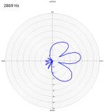
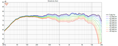
As most of you pointed out, the main difference between Boxsim and VCAD is the ability to integrate the speaker enclosure into the simulation and obtain the baffle step, phase, and polar plots. Regarding the polar plot, the dispersion is relatively uniform except in the vertical axis between 2600 and 3600 Hz, where a phase cancellation occurs at +15° and -15°.
Boxsim common outerhousing

Single driver Frequency response WS 17 E with baffle step

Vertical polar plot at ~2850 Hz
As before, I started by recreating the network presented for CLOU, and this time the resulting crossover makes more sense. I removed one of the woofers, adjusted the box dimensions to keep only the sealed enclosure (as shown above), and tweaked the network until I obtained a satisfactory result.
I retained the original architecture of the network. The adjustments mainly involved a stronger tweeter attenuation and a higher crossover frequency than originally. Additionally, I added a capacitor in parallel to smooth the tweeter response and flatten the +4dB bump at 13500 Hz.
The Total SPL graph shows a ±4dB curve between 46 Hz and 15100 Hz. (77.4dB ~ 81.4dB)
[Image: Network, Total SPL, and phase projection]
Project crossover network in Boxsim

Project Total SPL, individual SPL and Load impedance

Before and after adding 4,7mfd parralel capacitor in the tweeter network


Project phase responses

That concludes the transfer of the design to Boxsim.
I'll address a few points from my first post:
I have some new, albeit more general, questions:
So, I carefully took your comments into account and dived back into the rabbit hole.
Initially, I tried to export the data from WS17E and SC10N using Visaton Boxsim and then re-import them into VituixCAD. However, the results were inconsistent. I didn't take the time to verify the raw data thoroughly. Testing the majority of export options that Boxsim offers and checking the coherence of the curves and their responses to the network between the two software took a lot of time. Therefore, I decided to stick with Boxsim and trust it directly rather than relying on approximate exports and data.
The Boxsim Speaker Enclosure
As most of you pointed out, the main difference between Boxsim and VCAD is the ability to integrate the speaker enclosure into the simulation and obtain the baffle step, phase, and polar plots. Regarding the polar plot, the dispersion is relatively uniform except in the vertical axis between 2600 and 3600 Hz, where a phase cancellation occurs at +15° and -15°.
Boxsim common outerhousing
Single driver Frequency response WS 17 E with baffle step
Vertical polar plot at ~2850 Hz
Crossover
As before, I started by recreating the network presented for CLOU, and this time the resulting crossover makes more sense. I removed one of the woofers, adjusted the box dimensions to keep only the sealed enclosure (as shown above), and tweaked the network until I obtained a satisfactory result.
I retained the original architecture of the network. The adjustments mainly involved a stronger tweeter attenuation and a higher crossover frequency than originally. Additionally, I added a capacitor in parallel to smooth the tweeter response and flatten the +4dB bump at 13500 Hz.
The Total SPL graph shows a ±4dB curve between 46 Hz and 15100 Hz. (77.4dB ~ 81.4dB)
[Image: Network, Total SPL, and phase projection]
Project crossover network in Boxsim
Project Total SPL, individual SPL and Load impedance
Before and after adding 4,7mfd parralel capacitor in the tweeter network
Project phase responses
That concludes the transfer of the design to Boxsim.
I'll address a few points from my first post:
- The impedance seems less problematic.
- The ladder delay network seems costly and complex to implement for my limited experience.
- I will trust the Visaton plans and be concerned about potential box resonance during actual measurements.
I have some new, albeit more general, questions:
- Does everything seem coherent to you, or did I miss something?
- What components do you think I should have on hand and order in advance for the voicing stage?
Attachments
Hmm, already down to +/- 2 dB, so on average below our threshold, though if wanting a dip seems better to be at ~ 4 kHz where our hearing is most keen, hence can make music sound harsh.
Yes, consider GM's observation about the 4KHz peak.
I am not sure why the tweeter response takes the dip at 2Khz, but imagine its related to the parallel branches in the tweeter circuit. Save this configuration as a reference, if you haven't already done so.
What happens if you ditch the 33uF the 1.0, 0.82 and 10 parallel notch and change the 4.7 to 2.2uF with 2 ohms or thereabouts.
Maybe the phase has come more closely aligned, At the same time look at the bass Land C values by changing the Bass inductor plus/minus one E12 value and then re adjusting the Bass C value, trying to balance the overall response shape, a better phase match, and lessening the 4KHz bump at the same time.
If this doesn't play out well try adding another 6.8uF to the tweeter circuit on the tweeter side of the 0.22mH and re do the above optimisation. Dont forget to flip the tweeter phase from time to time to see you have a reasonably symmetrical notch.
Even after doing another iteration and maybe gaining some more ground, you will still change a few components when you start the final voicing and listening in your room.
Alternatively as its Saturday, chill and relax.
I think the tweeter network could be more simple. Did you try padding the tweeter after the highpass? Furthermore a designated LCR parallel to the woofer works better for baffle step correction than a single big coil, that often takes too much away at frequencies below the baffle step.
Its a fun one.
Baffle step is always fun with small baffles
And various trys you get 30 ohm peak at crossover.
I add further comp. but usually people scuffle about it
Baffle step is always fun with small baffles
And various trys you get 30 ohm peak at crossover.
I add further comp. but usually people scuffle about it
To answer GM, raymondj and markbakk :
The 33mfd in series of the 0.22mF causes the dip at 2000 Hz and greatly reduces an irregularity. The LCR parallel notch corrects the response at 5000 to 6000 Hz. Both of those applications in the network and the component’s values are from the original design.
I will definitely tinkle around with your suggestions in mind when I have more time to spare.
Here, I’m not sure if you’re pointing out the lack of screenshots for the off axis response graphs or not.
What is, in my opinion, significant enough to be mentioned in my previous post is the cancelation at ± 15° in the vertical axis between 2600 and 3600 Hz.
What is certain is that I will provide the complete off-axis graph rather than a single polar plot screen shot from now on.
How did you get the data for those transducers ? I went back and forth with FDGraphTracer multiple times myself, and after my original post, raymondj and markbakk agreed that I should use Boxsim to be sure that the data I use is correct.
The 33mfd in series of the 0.22mF causes the dip at 2000 Hz and greatly reduces an irregularity. The LCR parallel notch corrects the response at 5000 to 6000 Hz. Both of those applications in the network and the component’s values are from the original design.
CLOU original cross-over network

I will definitely tinkle around with your suggestions in mind when I have more time to spare.
I tried to stay thorough but concise in my posts, but if you need anything to provide your insight, feel free to ask and I will certainly do what I can to provide what I omited.Sim is not showing off axis response
which could expose issues.
Here, I’m not sure if you’re pointing out the lack of screenshots for the off axis response graphs or not.
What is, in my opinion, significant enough to be mentioned in my previous post is the cancelation at ± 15° in the vertical axis between 2600 and 3600 Hz.
What is certain is that I will provide the complete off-axis graph rather than a single polar plot screen shot from now on.
I think I understand it is your crossover version for this project. Is it possible to have a brief explanation of what your doing in this network ?
How did you get the data for those transducers ? I went back and forth with FDGraphTracer multiple times myself, and after my original post, raymondj and markbakk agreed that I should use Boxsim to be sure that the data I use is correct.
- Home
- Loudspeakers
- Multi-Way
- DIY Small CLOU design variation
