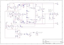
My first 150W amplifier using TIP2955/3055 transistors with overload protection using op-amp.
This amplifier is motivated by the need to protect the whole system against inrush current when the input signal is high. In fact, these protected amplifiers are specifically required to do some modal analysis tests in vibration labs to drive shakers. We have come across high failure rate of amplifiers due to sudden application of input signals while the shaker is connected. Therefore, I designed this circuit to limit the current of the output stage using op-amps and few other components.
I also tested it with audio signals and speakers and it worked like a charm.
THD: 0.003%
Frequency response: 1 Hz to 37 kHz
Supply voltage: +/-24 to +/-30
Lifesaver components that eliminate HF oscillation even with no load/light load condition:
1. Feedforward resistor R24 (1k)
2. Bootstrap resistors R14 and R15 (1.5k)
3. Zobel RC on the output
4. Feedback capacitor C8 (100pF)
5. Also C5 and C2 have helped a bit more.
Note: You will need a good power supply and a big heat sink for the power transistors.
Rx is wire jumper or very small resistor say 1.2R
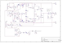
Attachments
150 watt is where current limit is at = 5 amp?
R14/15 at 1.5k puts CFP gain close to insanity.
30 volt rail be about 80 watts to 4 ohms.
Maybe 75 watt since single pair outputs would sag heavily
under load.
If using VI limited need flyback diodes on output.
R14/15 at 1.5k puts CFP gain close to insanity.
30 volt rail be about 80 watts to 4 ohms.
Maybe 75 watt since single pair outputs would sag heavily
under load.
If using VI limited need flyback diodes on output.
With +/-30V your max Vout is about 20Vrms which, with a 6 ohms load, gives you about 65W out, on a good day.
I think you have to review the numbers.
Also, curious to see a gain of 20 just in the output stage.
How did you measure that 0.003% THD, which frequency, what power level?
R3 and R2 give very low drive to the output stage (there are two R2's, and the 2nd one looks incorrect, but I guess you know which I mean).
Are you sure this amp has been build and is actually working??
Jan
Last edited:
I nearly missed this: do you realize C4 is a problem - it breaks the feedback loop at DC, meaning the quiescent output voltage of the amp is undefined. Pretty sure that's causing issues for a shake table actuator as the actuators may max out against the endstops (that's what happens with speakers in the same situation). I presume R22 is there to trim out the output offset, but I doubt that's very stable as the devices warm up. Configuring a DC coupled amplifier removes the need for such an offset trim circuit - your feedback network already is designed with this in mind (C7 is there to reduce DC gain to unity, so that the output offset is no larger than the input offset).
Also, given you AC-couple like this, C7 is actually unnecessary, and in fact means that U1A could see +/-25V on its inverting input if the output section lets go and latches up to a 30V supply rail...
I'd suggest losing C4, and improving the output section with modern output transistors which have decent gain at high current 3281/1302's for instance, and think about how to protect the inverting input of U1A in fault states.
Its recommended to limit the gain of a CFP output stage to x2 or so for good linearity - if you the want +/-30V swing a CFP gain of just 3 means the opamp swing is +/-10V, which works if the opamps are powered from the standard +/-15V.
Why did you chose exactly the TL064 chip? It is optimized for low current demands in battery powered wequipment, but otherwise compromized. Better use the TL074.
Best regards!
Best regards!
Thank you @WhiteDragon and @jan.didden for your review, there was a small mistake in calculating the power.
I used 4 ohm resistive load at 5A RMS, so the power was 25 * 4 = 100W and the applied voltage was +/-30V.
With the 6 ohm load, I will need 30v rms and that's mean +/-42V supply to obtain 5A rms which puts tip2955/3055 under high stress.
So, the amplifier will output 100W on 4 ohm load.
R2 and R3 are both 100 ohm, sorry for the copy and paste mistake during the schematic drawing. @jan.didden yes the amplifier was built and it is working, the THD was measured using 24-bit FFT analyzer at 4 ohm load and 5V rms, sine wave at 200Hz, the sum of 10 harmonics power is 0.003 of the main component.
Attachments
Thanks @Mark Tillotson for this detailed review. In fact, i used C4 to overcome some hf oscillation at the early stages of the design. I noticed that U1A output is drifting during few seconds until saturation, so I inserted R27 to compensate the drift. R22 is used to balance the arms and obtain 0 volt at output when the input signal is 0. I have noticed that the output remain balanced after components heating due to operation.I nearly missed this: do you realize C4 is a problem - it breaks the feedback loop at DC, meaning the quiescent output voltage of the amp is undefined. Pretty sure that's causing issues for a shake table actuator as the actuators may max out against the endstops (that's what happens with speakers in the same situation). I presume R22 is there to trim out the output offset, but I doubt that's very stable as the devices warm up. Configuring a DC coupled amplifier removes the need for such an offset trim circuit - your feedback network already is designed with this in mind (C7 is there to reduce DC gain to unity, so that the output offset is no larger than the input offset).
Also, given you AC-couple like this, C7 is actually unnecessary, and in fact means that U1A could see +/-25V on its inverting input if the output section lets go and latches up to a 30V supply rail...
I'd suggest losing C4, and improving the output section with modern output transistors which have decent gain at high current 3281/1302's for instance, and think about how to protect the inverting input of U1A in fault states.
Its recommended to limit the gain of a CFP output stage to x2 or so for good linearity - if you the want +/-30V swing a CFP gain of just 3 means the opamp swing is +/-10V, which works if the opamps are powered from the standard +/-15V.
To protect the inverting input of U1A , we can add a couple of diodes.
I will remove C4 and check the performance. Could you please advise why should we limit the gain of the CFP to 2 or 3 ?
@Kay Pirinha it was available in my components jars, I will buy 084 or 074 in the next designs. Thanks for your suggestion. I have noticed that 064 also perform well.Why did you chose exactly the TL064 chip? It is optimized for low current demands in battery powered wequipment, but otherwise compromized. Better use the TL074.
Because you soon lose the inherent good linearity of a CFP section that way - driver current variations (which are not linear) appear across the divider resistors and pollute it. A plain CFP can manage 0.05% or so THD, your version might be more like 3%, and load-dependent gain too.Could you please advise why should we limit the gain of the CFP to 2 or 3 ?
The 064 has a much lower slew rate. It’s plenty fast enough for when the feedback is in control of the amp, but not when it’s not. Clipping recovery will be far better with a faster op amp. Noticeably better with the 074, and still that won’t get you into “audiophile” territory. Fast enough where clipping still sounds clean on big PA amps, so it gets “good enough”.
And if you do drop the CFP gain, you need even more speed in the op amp. If you went down to a gain of 2 or 3 you’d need the 074 for sure.
And if you do drop the CFP gain, you need even more speed in the op amp. If you went down to a gain of 2 or 3 you’d need the 074 for sure.
Thanks @wg_ski for the advise, I 've ordered tl074 and will place it instead since I am using round socket and can easily replace the ic.The 064 has a much lower slew rate. It’s plenty fast enough for when the feedback is in control of the amp, but not when it’s not. Clipping recovery will be far better with a faster op amp. Noticeably better with the 074, and still that won’t get you into “audiophile” territory. Fast enough where clipping still sounds clean on big PA amps, so it gets “good enough”.
And if you do drop the CFP gain, you need even more speed in the op amp. If you went down to a gain of 2 or 3 you’d need the 074 for sure
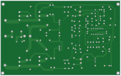
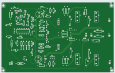
external heat sink and use wires to connect power transistor. This is development board, when everything is fine, I will make larger pcb with onboard heatsinkHow were you planning to heat sink those outputs?
- Home
- Amplifiers
- Solid State
- 150W overload protected amplifier