Quick question about F6 vs F5

Apologies if I have missed a previously posted answer. However...

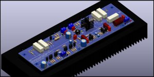
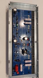
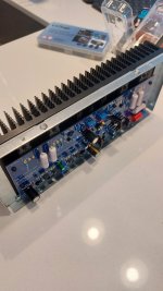
When extending amplifier performance to higher power the F5 is typically chosen as the starting point; F5, F5 Turbo V1, V2, V3...

Assuming that one will need to use multiple matched devices to spread thermal loading and that one wants near identical performance from all devices to provide best cancellation of `errors', wouldn't it be a lot easier to find near identical performance using a single device type rather than try to match complementary pairs?
Wouldn't the F6 be a better starting place?

Is the answer as simple as the problems introduced by trying to get well matched complementary pairs are outweighed by the errors introduced by adding a transformer?
Hoping for illumination,

Renkforce E-SA9 noisy on one channel

I'm trying to fix a Renkforce E-SA9 that is noisy on one channel. I know the amp is crap and worthless but I'm determined to fix it.

The right channel works fine but the left channel is noisy. The source signal can be heard but is drowned in hissing white noise (no popping or crackling). This is the only schematic I can find for the amp (attached below): Renkforce E-SA9 Stereo amplifier 2 x 12 W Silver (metallic), Dark brown | Conrad.com It's not quite accurate since some of the caps are electrolytics on the schematic but on the actual board are surface mounted non-electrolytics. Some other electrolytic values are different.

I'm using a signal generator app on a tablet to send tones. Probing around with an earpiece I can hear the noisy signal on the output cap of IC2a pin 1 (red arrow below). There is no noise on the same cap on the right channel (green arrow) which uses the other opamp in the dual package.

I've replaced both JRC4458 dual opamps and the red arrowed 10uF SMT cap. I've lifted the supply pins 3 and 5 of the output LM1875 in case the noise was coming from the output amps. The noise is still there.

Any ideas what might be causing it, what might be worth changing?

many thanks

Attachments

Speaker question

About 15 years ago the church I go to was doing a clean out and they were gonna toss a pair of Argos column speakers in the dumpster so I asked if I could toss them in my car instead.

Maybe a year or two later I gutted the drivers and used the following drivers.

Four Dayton Audio DC-200-8 8" woofers wired in series/parallel for an 8 ohm load.

https://www.daytonaudio.com/product/25/dc200-8-8-classic-woofer-8-ohm

One Pyle Pro sealed back 8" midrange.

One Eminence APT-80 tweeter mounted to an adapter made out of a piece of wood so that it could mount to the 8" hole properly.

I used an Eminence three way crossover, a zobel network on the woofer and midrange and the proper resistors for the l-pads.

I proceeded to seal the cabinet up as best I could.

Until recently the speaker worked fine and I even built another one last year.

I recently found I had done the l-pads wrong so in the process of removing the back off one, the cabinet had to practically be destroyed.

The cabinets were made out of some type of chipboard or something not really meant for being hauled around like I use them as they were intended to be mounted to a wall for a few decades.

I used a third cabinet I have as the replacement.

I then realized only the original two (got two more for free for fixing an old Peavey powered mixer) are the exact same size and the other two are slightly different sizes.

So I came to the conclusion that it would be best to get two proper cabinets built for two reasons.

1. Much better durability and the ability to add handles and casters.
2. Can go with a larger cabinet for better bass response.

As is the speaker produces decent bass to about 35Hz and gradually rolls off below there.

Also the current cabinets when powered on about 200 watts sitting on concrete will walk backwards when lower bass is being played.

I can post measurements of the cabinet when I get home from work.

The cabinets just do fit in my car lengthwise. Given I'm using a small tweeter I could reduce the height of the speaker by maybe 3-4"

The speakers are arranged vertically and the cabinets are not much wider than the 8" drivers.

What should the width of the cabinet be?

I'd also like to make these powered speakers and install a decent quality full range plate amp that can put out at least 240 watts (higher wattage if used with a limiter) if there is such a thing. I'd recess the amp in the back panel so that the controls will not extend past the back panel of the speaker.

I know the depth of the cabinet will have to be increased for the plate amp to be able to fit inside.

For the drivers I may mount them from the front using t-nuts and will use grills that fit each speaker.

I may also use t-nuts for the rear panel so that I can easily open the cabinets if need be.

Also what should the thickness of the wood be?

My old 1993 tube amplifier and 2023 SPICE

So, I'm retired now, supposed to have plenty of time for all my left-over projects. Not.

However one of my projects in 1993 was a tube amplifier, which I designed my self using manufacturer data sheets for the tubes.
Once completed I found that it had a perfect electrical characteristics, I used only audiofile components, connected the amp to good speakers. And I did not like the sound at all. And the wife did not like the size (2 monoblocks @ about 10kg each). Now 30 years later, I would like to try to complete the project.
Since I have totally forgotten how I calculated the amp (I found tube graphs with lines drawn across them, some resistor and gain calculations, harmonic distortion calculations) but now I'm clueless how I did that 30 years ago. I still have a lot of spec sheets.


Each monoblock is composed of three stages, a floating paraphase input stage which delivers two 180 degree out of phase signals. It uses a 12AX7-WA milspec double triode. The second stage is a double triode (6SN7GTA) which just amplifies the 2 signals for the endstage, a pair of 6550A's in ultralinear mode. The output transformer is tailored for the 6550's in UL mode. I recall the amp working stable (no oscillations)without feedback circuit, and covering 20Hz-20kHz. But since i recall experimenting with FB I'm not sure how linear the amp really is.

It appears that since 1993 there have been a few technology changes, such as the invention of the internet and the development of something called SPICE.

After this introduction I'd like to pose my real question. Since I cannot recall all calculations, would SPICE help to simulate the circuit?
Doe SPICE work well on a Mac? And most importantly, where do I start?

I would have to do some reverse engineering on my own design to get all the componentvalues and the final diagram though 🙂

TIA,

Johan

Need linear power supply for WIIM Pro Plus advice, please:)

Deep into a multiyear complete rebuild of our to be very high end(but very reasonable cost) full time RV and just no time or brain power for DIY right now(maybe ever🙂 I just need a decent streamer, plug and play, and have seen reviews of the WIIM Pro Plus with the supplied wall wart, IFI SP and more costly linear supplies but no budget for an expensive one at this time due to the money pit we live in and love.

Looking for a good assembled PS board, I can make up a case easily enough, or in a case, best for the money I can get but want to keep it under $100 so please help me out with your recommendations, it will be much appreciated🙂

------
I have quite a bit of great audio gear, DIY and factory including horns, tubes, D class, OB, etc.....and always roll my own cables for decades now. I be testing many speaker designs to see what I can make work the best when I get much more of the remodel done as well as playing with DIY amps, maybe DACs, streamers, etc but that is at least two years away.

------

NOTE: I am highly shielding the RV and only plan to use wired internet, blue tooth on certain occasions and no wifi so the WIIM might not work with our Tablet or phone but have not found that out yet, I would consider BT if possible or go wired so please let me know of any advice you can offer.

Thanks!
Rick

How much windowpane brace is too much?

At what point does a windowpane brace become too restrictive, cause resonant cavities, etc... The best I can reason is that is the brace is looked at as a port to the cavities it separates, as long as the "tuned" frequency of those windows (ports) and cavities are well outside the design Fs all would be well.

This question came to mind as i was looking through some pictures and came across my sealed UM-18 box. I will be opening up soon to add some stuffing so I could cut out some voids while I'm in there. Necessary?

1671052760231.png

1671052778662.png

Options for port shape & location - 15" Tannoy DC Build

Hello all.

I was hoping some of you more knowledgeable people will be able to help me with the various options and best practices for my build.

I have almost finished building cabinets for my Tannoy MG 15's, I have built ~160L cabs in order to bring the driver up to ear height. Constructed from 19mm veneered MDF, pretty well braced and initially lined internally with dynamat and open cell acoustic foam.

I have left them as a sealed cabinet for a little testing during setup but am looking to port them and have been advised to tune the port to around 30hz.

Aesthetically, I would prefer a slot or rectangular port either low down on the front baffle or around the mid-point but wanted to make sure this will not detrimental to the performance of the finished speaker.

Thanks in advance.
IMG_4565.jpeg

IMG_4558.jpeg

IMG_4562.jpeg

Recapping KEF 104

I've got a set of KEF 104 (not the ab version) which I'd like to recap as the caps are buldging and lots of things sound wrong with the output.

The crossovers currently have Elcaps in the following properties.

1x4.2uF 50V
2x5uF 50V

I'd like to replace them with something of a similar quality (or better if not too expensive). Could someone please recommend a capacitor type and reasonable brand?

Falcon Acoustics have Solen "Alcap" caps which are rated to 400V. Would these be a good replacement? I'd get a 2 + 2.2 to replace 4.2 which they don't seem to have.
Or is there something more suitable?

Thanks

Denon PMA 900V Power Capacitors

I have a Denon PMA 900v that sat for awhile unused. I opened the unit up and inspected it before trying to power it up. It immediately blew the main fuse (appears to be original) and the was a spark around main capacitors. I pulled the power supply capacitors to check them. 4 of the 6 capacitors read within spec ( I am going to replace them anyways) and 2 read dead short. The capacitors are 8200uf 72v (35mm x 70mm) electrolytics. I considered replacing them with 10000uf 100v capacitors but read somewhere about there being a concern that these amps do not have in rush control. Any advice, recommendations on suitable replacements. I plan to recap the entire amp as well while in the process; which brings me to my second question. I am considering replacing the ceramic capacitors in the signal path. What would be best in their place? Thanks.

FM tuner finished

Here we go all working - results are very good sensitive and selective. I can post the kicad stuff and code and alignment if interested.

Attachments

  • 20231119_104832.jpg
    20231119_104832.jpg
    248.4 KB · Views: 194
  • 20231119_104819.jpg
    20231119_104819.jpg
    418.5 KB · Views: 206
  • pcb.pdf
    pcb.pdf
    649.4 KB · Views: 131
  • tuner.pdf
    tuner.pdf
    1.7 MB · Views: 203

CBT with Crosstalk Cancellation?

I've been looking for an excuse to build a CBT for nearly a decade now. The thing that always stops me from "pulling the trigger" is that the high frequency performance of arrays is not great. It's a really difficult problem to solve that, because it's not as simple as adding a tweeter to an array, if you're going to add a tweeter, it will likely require dozens or even hundreds of tweeters to get the beamwidth of the midrange array to match the beamwidth of the high frequency array.

Another technology that I've had good results from is Crosstalk Cancellation. I've tried a bunch of different recipes to do that, everything from Polk SDA style arrays from the 80s, Crosstalk Cancellation via DSP using MiniAmbio and various Windows plugins. Opsodis is another oddball Crosstalk Cancellation scheme that never really went anywhere.

I was pondering these two topics, and it occurred to me that the two may be compatible. IE, CBT arrays have some issues, and Crosstalk Cancellation ALSO has a ton of issues. But the combination of the two may be synergistic.

HCA-2200 OP Amp Replacement AD825

I know this is an aging amplifier but any help would be appreciated.

I have acquired a used Parasound HCA-2200 Original Version. I am going to recap it soon. My question comes in regards to the OP Amp. I have read countless articles where John Curl and others say to either bypass the IC with a shielded RCA or to replace the OP Amp AD712 with AD825.

https://www.audioasylum.com/cgi/t.mpl?f=tweaks&m=56113
This is the best resource I could find on the LC Audio AD825 Type 1
https://www.octave-electronics.com/lcaudio/ad825.shtml
The website of course is overseas and I don't believe I can order from them.

I found this site for single to dual op amp adapter.
https://www.cimarrontechnology.com/product/browndog-020302-single-to-dual-op-amp-adapter

I have attached the original HCA-2200 schematic along with the Cimarron Adapters Schematic.

Can anyone verify that the Cimarron Adapter will replace the HCA-2200 AD712 op amp?

Anyone want to chime in on experience with these amps?

I plan on replacing all electrolytic caps. (Board and main)
I am going to change the resisters at R125 (R225) to Holco H4 https://www.diyaudio.com/community/threads/holco-h4-resistor-old-vs-new-how-to-identify.381120/
Per previous recommendations, I will remove the film caps on the main caps that are wired together.


Anyone recommend replacing rectifiers or resistors? Film caps?

Attachments

Hello from Petaluma, California

Hello all,

It's a pleasure to finally make an account here, having lurked for many years. I was a musician first, then an audio engineer, a luthier, a film photographer, a teacher, a builder. I started dabbling in electronics troubleshooting and repair, having been first bit by the bug by an electronics kit in grade school, then getting into amateur radio, then building my own 86 PC very early on, and began troubleshooting and repairing my own bass/guitar amplifiers and pedals with the guidance of an experienced local tech. I got into instrument repair and building after that. I was a touring musician for many years in Kansas City and New York City. I started attending Burning Amp not long after I landed in the Bay Area in 2015. The crown jewel in my current listening system is a Pass Labs INT-60.

I am very much looking forward to BAF coming here to Petaluma this year and to all the future events and connections to come!

Here I am on the left with NY percussionist Annette Aguilar and frevo/forro legend Spok from Recife, at this year's California Brazil Camp in Cazadero, CA.

IMG_6013.JPG

Retired and working more!!

Hi All, I've been a long time voyeur of diyaudio whenever I had a problem to solve so now that I've retired - as of May after 47 years in electronics - I thought I'd make it official and join the fun. We just moved cross country to North Carolina from California and I'm in the process of setting up my bench for repairing vintage stereo's - 1960-80's Marantz mostly as the first 3 years of my career was working for Superscope / Marantz in Chatsworth Cali. Never had the time while working but now.... And of course most of my test equipment is broken in some way or another along with being wayyyy out of calibration so that's first up - already had to fix a Tek 2465 scope for the fusable caps and exhaust fan. Looking forward to delving into the brain trust and hopefully I can add some knowledge to the effort...

Hi everybody!

Hi all! I'm in my third year bachelor's degree in Electrical Engineering, loving every second of it as it gives me ways to better understand my passion for everything audio-related. Been a big fan of quirky vintage electronics for a while now, especially old video games, and also toys (love you for that dad 🙂 ), but I've always had a thing for audio equipment. I tend to prefer messing with stuff diy-style (the cheaper the solution, the better!) even when things get hairy!
I'll be delighted to soak in all the info you guys might give a novice like me!

Turntable motor options (DIY)

Hey

I'm in the process of trying to piece together a DIY turntable (as in i buy all the assembled parts and just put it together). I've gotten most of it figured out, but I'm having trouble with the motor. I am sensitive to pitch change so speed drift is an absolute no go for me... To me my options are as follows:

  • Buy an origin live kit (bad reviews?) or a different motor kit, and hope for the best in terms of speed stability
  • Buy a project rpm 9 motor or similar and look into speed controllers
  • Buy the 24v rega kit with a neo psu
  • The Sota eclipse set with the tachometer (redicolously expensive because of import fees, and does it even work in the EU?)

Ideally i get something like the Sota with a tachometer but it seems like everything in europe is just DC motors with simple voltage regulators. Any ideas?

MXR headphone amp(i need help)

I tried to simulate the mxr circuit with the pspice, but the results don't seem to come out as I thought, so I'm going to ask a question. The closer the original volume resistance is to zero, the bigger the waveform should be
It's true that it gets bigger when it's actually simulated, but the output signal is too low compared to the input signal, so I don't know what the problem is

I thought I drew the circuit diagram wrong, so I redrew it, and the results were the same.

I think it's an opamp problem, so I changed the opamp, but the same result came out
What's the problem?

1700321956741.png


1700321942437.png


1700321991939.png

Adding a rear-firing tweeter to existing speakers

I have a pair of DIY Amiga MT speakers made from a parts-express kit that I am sure many of you are familar with.
If not they are a 2-way, ported, floor standing using a 7" woofer and the Peerless DX25TG59-04 tweeter.
This is their crossover:

1700082152304.png


Basically I would like to use them to play around with the concept of a rear-firing tweeter. See if it matches my room and my taste...
But I have a few questions before I go tearing my speakers apart. I am very much a beginner to all this so please correct me if I am making any bad assumptions.

Driver: Duplicate the existing tweeter?

Physically: where to mount the rear tweeter? On axis with the primary front tweeter? Top mount?

Electrically, what is the easiest way to integrate these into the existing crossover? Presumably an L-Pad and a switch to disable them would be a good idea?

Interested in your thoughts as well to this idea but keep in mind its just an experiment.

LJM L12-2 New build Need a guide

Since have an good quality 500w smps from failed Dclass project laying around for some time. Now I want to use it to built HQ amp with xlr inputs that would be used both for home-FI use and small parties like birthdays and so..

Supply is +-55v
Looking for stereo amp, but if it could be made so can be used in bridge mode too, it would be great.
Also would like to use all quality components.
Am going to buy those in a kit so please recommend supplies in EU if think I should replace any.

Here is a link of supply.
https://connexelectronic.com/product/smps500rxe/

Unbalancet to balanced xlr kit.
https://a.aliexpress.com/_mrhkBLI

Protection module.
https://a.aliexpress.com/_ms8PWj2

L12-2 kit.
https://a.aliexpress.com/_mLMe1uC

Enclosure and heat sink would weld out of aluminium.

AMC CD8 Restoration

Dear diyAudio

Greetings! Long time lurker, first time poster.

Background:
Previous owner said it cannot read disc, and said even the disk is not spinning. Upon receipt, I proceeded to clean the lens, lube the spindle motor and also the sled rails (sewing machine oil - I dabbed some onto a cotton bud, and then wiped it on the rails). Laser assembly is KSS-210. Plugged everything in and started it up with a CD (~41 mins, early 90s, John Lee Hooker). The CD spins, but it took a long time (~60s) to read the TOC. Once TOC is up, I played track 1. It plays, but with a fair bit of distortion (like dirty vinyl?). It also mistracks somewhat, and finally gave up (back to TOC) at the 2min mark.

2. I then pulled out all the ribbon connectors from transport to board, cleaned the contacts and reconnect. At this point, the lens did not hunt (and hence, no spinning of disk). Stumped, I tightened all the ribbon connections and now it does read the TOC and plays. [ribbon / connectors faulty, cold solder?]

I noticed the playing is smoother, albeit with 1-2s skips, and I can get it to select all the tracks in the CD (all 20). Interestingly, the longer I allow it to run, the distortion seems to get lesser. It did refuse to recognize longer CDs (>60 mins). Newer, louder CDs (post-2000) under 60 mins can be recognized, but the distortion was so harsh it was unlistenable. It sounds like it was clipping?

3. On close inspection of the board, C503 and C504 are bulging. C208 and C209 are suspect too.

At this point, what would be my next course of action?

1. Change out the suspect caps?
2. I have a scope, so attempt tracking / focus adjustment?

Attached is the service manual, and a couple of videos to demonstrate the sound quality in a downloadable link. https://fileport.io/9XpST5wy4bhp

Thank you!

Should I connect all power supply ground together?

As above. I'm just unsure if it's safe to connect the ground if the 2nd diagram to ground if the first diagram (which are basically the transformer secondaries).

So I got 2x of this supply. (2 separate transformers with dual secondaries each. The 2 wires from the 2 secondaries were connected to make center tap)

Screenshot_20231120_001037_Chrome.jpg


And 2x of this supply. (1 transformer with dual secondaries. 1 secondary for each bridged rectifier)
IMG_0056.jpeg

Thanks in advance.

Danley finally condescends to home market? TDH-3 & c

I've been away awhile. Pardon if this has already been posted. I did a quick search and saw nothing abou them. Seems DSL has added some new smaller speakers to its range. Website is broken right now, so all I have for reference is Sweetwater (where I saw them listed.) Although part of his studio line, these are, I believe, the closest to a "normal" home hi fi speaker DSL has produced to date, and only slightly into the four (rather than five) digit range. See, Tom? Not so hard. You've done well to branch out from marketing to pro audio, stadiums and the ch- ch- chur- 😱er, buildings with the funny shaped plus sign on the roof 😈

Now all you need to do is produce a six digit range, in rare woods, with exotic drivers and crossover components made with precious metals, with capacitors filled with the blood of unicorns and inductors hand-wound by virgins under the full moon in the enchanted forest. 😎

Specs look nice. I'm sure they're nice speakers, but I'm quite content with my pair of used SH-60 at the same price. Granted a bit overkill for a living room, but after six months, I've no complaint (unless you count not finding a buyer for the pair of SM80 collecting dust to one side. Oh very well, luxury problems I suppose. ) 😡

https://www.sweetwater.com/store/detail/TDH3--tom-danley-tdh-3-3-way-passive-loudspeaker

First Watt Clone/ACA/Akitika for a first time builder

I really want to try my hand at building an amp for myself. I can solder and I should be able to competently stuff a mildly complicated board. It just seems like a project I will want to do until I try it. I felt the same way about recapping and rebuilding a few older speakers. I just wanted to see what all the fuss was about.

I have done a lot of reading here and elsewhere to get to this point. I have a few decisions to make so I am here looking for advice and comments. I would be pairing the amp I build with a 1 year old pair of Zu Audio Omen Dirty Weekend mkII speakers. These speakers are pretty efficient and they feature a nearly full range driver with a super tweeter crossed at 12k. Right now they are being powered by an Adcom GFA-535 that my wife found in a thrift store a few years ago. I really like the way they sound, but I can't help thinking they would sounds much better paired with a better power amp.

I recently read through Paul McGowans book about stereo setup and after moving my DWs around I am convinced that I am still a long way from getting the best out of them. This amp will just be the next step along the way.

I listen to just about every type of music, but spend the majority of my time with mellow electronic, jazz or rock and roll playing. I would use a combination of input and would be able to choose between an Anthem TLP-1 or Yamaha WXC-50 as a preamp to start with. At the moment the Zu Audio DWs are in my office (13x11), but I may look to move them into another larger room as I think they need more room to breathe.

I was trained (many years ago) as an electronics technician (aviation) by the Navy so I remember enough to be dangerous. While I still work in the field, I have not worked on gear directly for a few decades. I have a decent soldering iron and all the basic tools and supplies that should be required.

The reason I am thinking about a build for my DWs is all my other speakers require a LOT more power. Both other sets are currently getting at least 200w. I could look for something to build that puts out that kind of power, but it seems more dangerous and potentially much more expensive. I may get there someday....

I am looking to the First Watt clones or Amp Camp Amp because both are well established, well liked and seem like they are potentially a great match.

I did run my DWs on a flea power AppJ tube amp and the sound was great. I have experienced what the DWs can do with just 3w. I imagine 25+/- watts from a carefully designed class A nelson pass design would be pretty good.

The ACA looks to be a pretty simple and was designed to be put together in an afternoon so I imagine it would be the easiest option. The kit comes with everything I would need and the cost is relatively low. My main concern is I will get it together and find that my apatite is only wetted and I immediately want more...

In the same price range is the Akitika GT-102. I am not a fan of how it looks, and it looks like a very different animal. Not necessarily better or worse just a different direction.

Looks to me like the aleph J or F6 would come in under $800 so I guess another question would be if there is something else out there for that cost that should be on my short list?

Questions and comments are welcome. Thanks for reading!

Calculate Total System Impedance

Hi all,

Sorry in advance if something similar has already been posted.

Long story short, I have a couple of new sub cabinets which I wanna set together with another two-way speaker in my living room (for the time being I will only set 1 sub and 1 two-way top). Anyways, I was doing some calculation to see if my amplifier is up to the task but I'm worrying the overall impedance comes out to be 2.66 Ω, while my amp can only support 4-8Ω.

What confuses me is the role the passive crossovers play in the calculations. I feel like this is all in parallel right? is there any way I can sort this out without aving to get a second amp?

The amp I'm using is a digital Kam KXDR 1600.

here is a simplified schematic of the connection (Mind I'm only using one output channel on the amp set in mono).

Thanks in advance.

Scheme-it-export-New-Project-2023-11-19-18-30.png

Hiraga Super 30 droning hum

Having an issue with my Hiraga Super 30 Class A amp.

Had a small hissing sound, so rewired the signal in wires, and the speaker out wires. Also removed the speaker protection boards as I was concerned the small/cheap 12v transformer was causing the hiss. Redid the ground wires as well.

Now, I have a loud droning hum when connected to my Cary preamp.

With nothing plugged into the Hiraga, it’s virtually silent. When I plug my MP3 player into it, no hum. But, when I plug the Cary in, it drones like crazy.

When I plug the Cary into the Sony VFet amp, no drone. When I plug the Cary into my Adcom GFA 545, no drone.

What the heck us going on?

Any thoughts would be greatly appreciated!

P

News from Feastrex Japan

I just received some new pictures for their new development!!
Anyone any idea??? 😀

An externally hosted image should be here but it was not working when we last tested it.


An externally hosted image should be here but it was not working when we last tested it.


An externally hosted image should be here but it was not working when we last tested it.


An externally hosted image should be here but it was not working when we last tested it.


An externally hosted image should be here but it was not working when we last tested it.

Digitize lp records problems

I have digitized hundreds of lps with audacity and Spin It Again, but now the feed from my turntable is intermittent. I thought it was an electronic issue in my audio Techniques turntable so I bought a new Ion turntable with on board speakers . Lps play fine but when coupled to my pc to digitize the sound is intermittent. I'm not an electronics brain so I'm in need of help. Any ideas would be appreciated.

Optimum membrane area for natural reproduction of vocals?

I have made a few 3-ways with nice, robust drivers, and with those type of drivers I prefer 2nd order acoustic filters. Regardless of the speaker's size and sound level, and regardless of how each driver is constructed and implemented, it appears to me that there is always a connection between the Sd/Hz and the speaker's ability to reproduce natural and recognizable vocals. It has often surprised me how the optimal crossover – for me – ends up ½ octave higher than I had expected, based on what is recommended crossover for the drivers on various forums, as if a larger Sd alone adds "something" critically important that makes vocals "more correct". Difficult to describe.

Anyone with similar experience? Pushing tweeters and midranges too far down in frequency, … a bad habit?

I can mention some examples of crossover for drivers that I know well; my choice, and typical forum-recommended crossover which is ½ octave lower:

OWI 5000Hz (3600Hz)
Millennium 2800Hz (2000Hz)
MDM-55 1400Hz (1000Hz)
Seas MCA11 800Hz (500Hz)
AT 15H 500Hz (350Hz)

How far down a driver should be pushed depends, of course, on how the driver below it performs in its upper working range. A light, quick and clean-playing woofer can push the crossover reasonably high. And a light and quick midrange can push the crossover higher than “expected”. In any case, my point is that the speaker often sounds better when the midrange and lower treble get a slightly larger Sd than was originally planned for.

Perhaps they knew what they were doing, the gurus in the 60s/70s who believed that vocals on radio and TV sounded best when the entire midrange was covered by a widerange 8". Perhaps it is not just out of consideration for the lower octaves that todays high-end fullrange drivers are 8"?

In my old days, I have gained increased respect for vintage speakers with a typical 8" woofer, 4" midrange and 1.5" paper cone tweeter, low order cross around 1000Hz and 5000Hz. They can't play loud, but they can reproduce vocals with terrifying realism and clarity.

Opinions?

GK 800RB Help request! (..yes, another one ; )

Greetings, I received a GK 800rb from a friend recently and although I've repaired a number of solid state bass amps, I've got questions about this one. When I received and opened it, and looked at the power supply board it was obvious something odd was going on. The PS board is the 206-0048-C version - and R3 (10 Ohm) was toast (see pic), also Q3 (MPSA56) had it's face blown off and Q2 (MPSA06) was inoperative.
I pulled and checked every component on the power supply board except the six 1000 uF/100V filter caps.
R1 & R2 (56K Ohm) tested spot on,
C1 & C4, C2 & C3 all tested fine.
I pulled and tested rectifiers KBPC603 & KBPC 2502 and they tested fine.
I pulled and tested the four C5 - C7 (470uF/63V) caps and all tested good.
I replaced the burnt R3 and it's pair R4 (10 Ohm)
I replaced the defective Q2 & Q3 pair (MPSA06/MPSA56)
I also replaced 16V Zener diodes D1 & D2 with new and also replaced Q1 & Q4 (TIP31c - [B.C.E.] installed) because of what I saw when I opened this amp.
In the pics submitted you can see where someone had attached the -15V (Red) supply wire directly to the emitter of Q4! And even more odd was that when I looked at the underside of the PS board, where the -15V wire is labeled on top of the board to go, it doesn't look like anything had ever been soldered there! After checking the schematic and looking at pics of other 800RBs I decided to put it where "it's supposed to go".
It's at this point where I could use some advice (at least)...
Having read possibly all of the GK800RB threads here on DIY I decided it was probably prudent to isolate the PS aboard before troubleshooting further. My question is this - as you can see in the pics I've disconnected all of the PS feeds to the amp board: Y/Or/P*/R/Bk (*the board says brown but it's purple on mine) and the Red -15V and the purple +15V supply wires with the molex plug is hanging off the side. Note: the black ground wire in the disconnected +/- 15V supply plug is still connected to one of the output jack sleeve/chassis connections (and I'm not sure if it should remain there during isolation tests)
Question: Is it correct that the Black wire on the board (the two secondary center taps) be disconnected also? Or should the Black wire be left in place to provide the ground when the amp while testing? And if this is the case, and it should be left in the PS board, does the entire rear of the amp actually need to be placed (screwed) back in the amp chassis during testing? Note: the other end of the black wire is connected to one of the output jack's sleeve/chassis connections also.
So, it's a "what's the correct way to isolate the PS for testing the PS board in the 800RB?" question. I've added the other info to illustrate my reasons for doing what I've done so far and the questions swirling around in my head currently.
Well, that's where I am right now. I'm awaiting further instruction in the troubleshooting of this amp from those that know more than I do.
All assistance and insight is appreciated. Thanks
Mark

Attachments

  • 1.jpg
    1.jpg
    94.9 KB · Views: 226
  • 20.jpg
    20.jpg
    196.3 KB · Views: 197
  • 21.jpg
    21.jpg
    216.6 KB · Views: 190
  • 11.jpg
    11.jpg
    249.4 KB · Views: 239

What are the differences in a buffer, line-stage, pre-amplifier and front-end

Reading posts and looking in the diyAudio store there are references to buffers, line stages, pre-amplifiers and front ends. While they seem to have things in common, I think the specific terminology indicate that there are differences, i.e., they aren't just different names for the exact same things.

So:
1) Could someone explain the differences between the devices listed above?
2) In what circumstances is one more applicable than another?
3) I know there are some headphone amps that are used as pre-amplifiers. What characteristics would make the use of a headphone amplifier acceptable as a preamplifier? (For example, maybe a certain gain of the headphone amp would make it unsuitable, or maybe some characteristic of an amplifier would make most headphone amps unsuitable).
  • Like
Reactions: Auld Gravy

Serial 16 ohms or Parallel 4 ohms?

I'm building a pair of ripole subwoofers with 2x 12" speakers and I'm getting to the point where I have to make a decision on whether to wire them in series or parallel. They are Peerless/Tymphany 830669 speakers rated for 8 ohms so the amp is going to see either 4 or 16.

The amp is an XTZ AP100 which is rated 2x110 W @ 8ohm, 2x180W @ 4ohm. I don't really care much about SPL, as the maximum level I'll be listening will be below 85dB and they'll be supplementing 2 Quad ESL57's running on a Quad 303 amp and I expect to cross at about 70 Hz.

Is there any advantage in wiring the speakers in series vs wiring them parallel?

Help with I2S input on an aliexpress PCM1794 DAC (Static)

Hello,

I purchased a PCM1794 DAC from Aliexpress, and when using their bundled LHY AUDIO Coax-to-i2s converter board, it sounds wonderful

However, I'd like to feed it i2s directly via hdmi cable from my DDC/Reclocker - but when I try feeding it i2s directly, I get mostly static. The static goes away when I grab and hold the i2s lines, so I know they are hooked up correctly.

I've been doing some reading of posts that have been posted over the years, it seems like some people say it's transmission line effect, and some people say it's due to reflections

I have two questions:
1. why does it work perfectly when I use the i2s output of the LHY AUDIO board? (the wires are the same length)
2. can I just solder in some 10 or 35 ohm resistors on the destination end (DAC side) of the wires? (I know that everyone says to put the resistors on the SOURCE side, but in my case the source is a DDC/Reclocker that sends out i2s over HDMI so I cannot do that)

Also I've read that people say you should alternate ground wires in-between your i2s lines, but how can I do that in this case, since the inputs are jumpers on the DAC board?

Thanks for any help you can provide,

-- Mike

i2s_1794.jpg

BOSE Model 360 Music System - actually Manufacturer of the Turntable wanted - maybe close to SANYO TP-92S/CEC BA-300 (BA300) ??

Attachments

  • BOSE Model 360 Music System OWNER's.pdf
    BOSE Model 360 Music System OWNER's.pdf
    4.7 MB · Views: 125
  • Bose 360 Turntable top-II.jpg
    Bose 360 Turntable top-II.jpg
    281.1 KB · Views: 161
  • BOSE 360 turntable  lid hinge-II.jpg
    BOSE 360 turntable lid hinge-II.jpg
    366.7 KB · Views: 107
  • BOSE 360 turntable platter.png
    BOSE 360 turntable platter.png
    241.2 KB · Views: 109
  • BOSE 360 turntable motor pulley.jpg
    BOSE 360 turntable motor pulley.jpg
    58.8 KB · Views: 102
  • BOSE 360 turntable tonarm weight.png
    BOSE 360 turntable tonarm weight.png
    181.7 KB · Views: 107
  • BOSE 360 turntable platter-III.png
    BOSE 360 turntable platter-III.png
    228.1 KB · Views: 98
  • BOSE 360 turntable lift+start.png
    BOSE 360 turntable lift+start.png
    186.4 KB · Views: 109
  • BOSE-360-turntable-lid-hinge-III.jpg
    BOSE-360-turntable-lid-hinge-III.jpg
    268.2 KB · Views: 109
  • BOSE 360 turntable  lid hinge.jpg
    BOSE 360 turntable lid hinge.jpg
    216.1 KB · Views: 107
  • Bose 360 Turntable 33-45 switch.jpg
    Bose 360 Turntable 33-45 switch.jpg
    13.6 KB · Views: 100
  • BOSE 360 turntable rear sticker-II.jpg
    BOSE 360 turntable rear sticker-II.jpg
    7.1 KB · Views: 100
  • BOSE 360 offer.jpg
    BOSE 360 offer.jpg
    669.1 KB · Views: 92
  • BOSE 360 turntable unp.-***'y instr..jpg
    BOSE 360 turntable unp.-***'y instr..jpg
    99.1 KB · Views: 104
  • BOSE 360 turntable owner's Cover.jpg
    BOSE 360 turntable owner's Cover.jpg
    70.8 KB · Views: 100
  • BOSE 360 turntable rear Owner's m.jpg
    BOSE 360 turntable rear Owner's m.jpg
    130.2 KB · Views: 93
  • BOSE 360 turntable rear sticker.jpg
    BOSE 360 turntable rear sticker.jpg
    87.1 KB · Views: 92
  • BOSE 360 turntable rear hinges.jpg
    BOSE 360 turntable rear hinges.jpg
    133.8 KB · Views: 98
  • BOSE 360 turntable rear-II.jpg
    BOSE 360 turntable rear-II.jpg
    69.6 KB · Views: 96
  • BOSE 360 turntable rear.jpg
    BOSE 360 turntable rear.jpg
    86.3 KB · Views: 93

Mission Cyrus one (Tog) Op Amp rolling

I am using a Cyrus one (tog) which has developed a crackle/popping noise. It is only audible when using phono input. I have replaced all the capacitors thinking that it may be a bad capacitor, but the noise is still there. It gets louder as the volume is increased.
I am going to replace the op amps on the board next, but wonder if OPA2604 and perhaps the LM4562 can be considered as a drop-in replacement in this particular case?
The picture included is before the recap. I have replaced 1uf and 2.2uf bipolar electrolytic capacitors with wima mks2.
Any advice would be greatly appreciated.

Attachments

  • 2.JPG
    2.JPG
    66.7 KB · Views: 207

Use of mini xlr connectors on unbalanced input / output

Hi,
I want to connect a preamplifier to an amplifier. The two devices (made by myself) are unbalanced and equiped with "ground loop breakers". To avoid problems with noise, humm and buzz I think it will be a good practice to use "mini xlr" elements to connect these devices. The shield will be connected to the chassis of each device but not to the reference wire. One wire for the signal and another for the reference source (connected to the ground's output / Input modules) will connect the two devices. The ground's modules are all connected by a star wiring to the "ground loop breakers" (2 in the amplifier and 1 in the preamplifier). Can you tell me if you have experienced this type of connection (with mini XLR or standard XLR).
Thank you

DIY portable audio recorder

I want to build a portable, robust SD audio recorder with two channels, 24 bit sample width, 96 kHz sampling frequency, phantom power and sturdy XLR connectors and pots. And high audio quality, of course.

As I am not an experienced programmer I thought of using an embedded linux board like the BeagleBoard, a 24/96 codec and a (touch)screen or the circuit of a portable sound recorder like the ZOOM H1 as a basis.

Any suggestions, ideas, comments?


Peter

Cathode Follower Voltage Rails/Headroom in Class B Output Stages

I've never thought too hard about CFs but I'm playing with the idea of DC coupling power tube grids for bias stability on peaks. Since there's now a negative rail the Ak voltage can get big pretty quick so it looks valid to set up a sort of bipolar supply for follower stage. So, I'm trying to work out how big of a positive/negative rail is needed and not excessive. From articles like this is seems that the load line is drawn normally but I'm still a bit perplexed.

Can a follower typically swing all the way to the positive rail as suggested by the load line? Like, If I need to pass a 75Vp signal is a 75V anode voltage (in theory) sufficient? Putting aside for second that the grid signal will be shifted down by the bias voltage. If one was unconcerned with supplying grid current to the power stage could the positive rail be, effectively, 0v since the power tube grid would clamp here as well?

It seems easy enough to determine how close to the negative rail the follower can go but is there a way to determine how low one needs to go into cutoff in a class B output stage? Does it make sense to have a follower capable of reproducing the the entire negative swing when the power tube will be in cutoff at some point? Let's say a -75v waveform peak plus a -50v DC bias, and then another 50 volts of clearance for where the follower's load line crosses 0vgk? -175v?

So, how close can you cut it?

Power supply for Purifi Eval board...

Hi all,

Just wondering about the requirement for the purifi Eval 1 PDR gate drive rail (15v) to be grounded to the main negative rail (nominally -65v). I have a large transformer with multiple secondaries, can I safely connect any nominally chosen wire to act as ground for this 15v line? More specifically I would have the linear stage, so the negative of the linear 15v would be connected to the -65v as ground.... Is that a safe thing to do?

Equally if I have two transformers and two separate supplies, so that one gives me +65/0/-65 and one 15v/0, is is save to connect the ground of the 15v to the -65v, and do I need to be aware of any risks?

In all cases I will be working with linear supplies and transformers, no smps intended.

Replacing IRS with Gate Driver + External Op-amp

Hello everyone,

I am following a reference design from Infineon based on their new IRS2461S IC (attached below). The IC contains an OTA + MOSFET Gate Driver, and I have chosen to replace it with an Op-amp + external MOSFET Gate Driver IC.

My question is whether I should do further changes to the modulation scheme to make it work, or if the modulation scheme will operate as is with the op-amp.

I have also noticed that the capacitor labeled DNP in the attachment is always taken out when switching from (IRS2092) to (IRS20957 + op-amp). Am I correct in choosing to not populate that capacitor for my final schematic design?

Thank you,

Attachments

  • image_2023-09-13_214453885.png
    image_2023-09-13_214453885.png
    29.2 KB · Views: 554

Desoldering compactron sockets

After exactingly populating Pete Millett's Mighty Midget board, I have made a fundamental error and soldered the compactron 6T10 sockets upside down.

We are talking about 12 pin sockets here so the process to correct this error does not seem simple.

I am planning to:

(1) snip the pins on the socket side
(2) order new sockets
(3) desolder the stumps of the pins using a pump and braid
(4) solder in the new sockets with the correct orientation

All with the hope the pads don't lift and I can get enough solder out of the pads to make the room for the new pins.

Does anyone have tips or a smarter approach?
IMG20230818142217.jpg
IMG20230818143342.jpg

QB3/200, any experience with these?

QB3/200 seems to be more or less the same as a 4-65A:

https://tubedata.altanatubes.com.br/sheets/030/q/QB3-200.pdf

I can't see anywhere in the datasheet a recommendation running theses tubes at cherry red plate, but I can't see the usual flash getter on the tubes.
From the Philips DS, there is an example of LF amplification at only 600V / 30mA per tube: 18W plate dissipation at idle.

When looking at Eimac DS:

4-65A.png


But there are operating points like 1000V / 60mA (for 2 tubes) so 30W at idle.

I suppose there won't be any red glow at the plate, from 18W to 30W, right ?

Do you know if it is mandatory to run these tubes at cherry red plate glow? if so, why did they provide these operating examples?

Thank you

Has anyone tried this approach to a "safer" Loftin White?

I found this on the Tube Cad website - https://www.tubecad.com/2015/12/blog0335.htm. It looks interesting and curious to know if anyone has tried this or something similar. I'm still a little unclear as to how the part values (type of NPN, resistor, etc.) would be specified but the approach makes sense.

Might not be in the less is more spirit of a Loftin White circuit but seems to address some potential concerns.

Thanks!

Screen Shot 2023-11-18 at 10.46.11 PM.png

amplifier Leak/Heco 2000 quiescent current help

hi
i own an nice receiver heco 2000(german version of leak 2000).it worked fine but had a loud hum noise(around 120hz).so i've replaced the 2 power supply capacitors.2 decent samwha 10000uf 63v(the original 6800uf 40v).the hum noise there is still but now is very slight.more audible whit low impedence headphones and through speakers(more hum noise from right speaker.
the dc offset is:right: 55mV , left: 75 mV.a little high?
I've set the bias on other amps(whit very clear istructions on service manual), but the process for this heco/leak 2000 is not clear to me as my electronic skills are a bit basic. Can anyone spell out exactly where i should be placing my digital multimeter black-red probes?i've seen where is it the potentiometer vr1(on main amplifier pcb.2 vr1..i presume one for left channel and one for right channel). I've attached the instructions from the service manual.photo of part of service which explains how to adjust quiescent current and 2 photos of electrical diagram.i hope the pages are clear
FireShot Capture 081 - Leak-2000-Service-Manual.pdf - .jpg
1FireShot Capture 082 - Leak-2000-Service-Manual.pdf - .jpg
2FireShot Capture 083 - Leak-2000-Service-Manual.pdf - .jpg

Semiconductor Variance

In my audio journey, I've have come upon the output stage. I have two questions:

1) Is there a discrete semiconductor that doesn't have a lot of variance in production? (I'm assuming there's no 1% tolerant transistor or the like)

2) When it comes to output stage, while chip amps do simplify design, does the cost proposition of them outweigh the performance of a high specced discrete amplifier?
  • Like
Reactions: rsavas

Need helps! Weird signal results on my DIY High-performance Hyrid MOSFET Audio Power Amplifier

Hi everyone,
I may have started my project with to much self confidence. I read the entire book "High-Power Audio Amplifier Construction Manual" from G. Randy Slone. I choose to build the High-performance Hybrid MOSFET Audio Power Amplifier from Figure 11.14. (See first image).
I redraw the entire drawing into the KiCad software (Linux) and created the PCB in the same suite software and have had it manufactured by PCBWay in China. It is my first experience as designing an audio PCB but I have a lot of experience with creating PCBs. I'll attach a picture of my drawing and a PCB capture, as well as some 3D views from KiCad PCB and some pictures of my final PCB. I share those for you to have as much as information to help me.

Now, my first mistake was with the orientation of the two upper MOSFETs. The original figure 11.14 doesn't specify the Drain and Source pin. The only note is the line going to the Gate. The upper MOSFETs have their lines over the center of the part while the lower ones have their lines under the center of the part. Unfortunately, in my software the library have the Source line in the center of the part. So I didn't notice this and even if I rechecked everything two and three times; shame on me, I didn't realized that mistake. It is my first experience with MOSFET, gee... I guess we learn from ours mistakes. Anyway, I was able to use my PCBs by crossing both Source and Drain pins of the upper MOSFETs.

After having fix this, I got the right +VCC and -VCC voltages. I use two Rigol DP712 Power Supply so I can start applying voltages from +/- 5 VDC and going up. But I cannot go more than +/- 8 VDC before the positive section of the Sine wave start to reach a limit as if the +rail limit was reached. Here I don't understand why this is happening when I actually do raise the Power Supply! And the more I raise it, the more the sin wave distord until the output signal goes off. I bet the MOSFET turn off from their internal protection.

I captured some screenshots from my Rigol DHO914S scope. It is a four traces scope. The trace 1 (yellow) is the input signal from my Rigol Generator, a 60 mV,1 kHz sin wave. The trace 4 (Blue) is the output of the Amplifier. The trace 3 (Rose) is the BIAS and finally I used the trace 2 (Cyan) as the testing probe in the circuit. This latest is what concerned me. I trace the signal starting from the Input and as I soon as I reach collector of Q101, I get this really weird signal, an envelop synced with the output signal. So I start to ask myself if this could be due to a very bad PCB design or if it is a result of a faulty part. This is where I ask your help. Maybe some of you are already familiar with this kind of weird signal. I took a zoom of the weird envelop and used the Cursors to measure the frequency and the level. That is the latest capture image; I read -401.5mV as delta Y and a frequency of 4.409MHz !

Any idea what could cause this? Could it be generated by my Drain and Source crossing?
My very best regards,
Yves

Attachments

  • Capture d’écran du 2023-09-21 08-44-06.png
    Capture d’écran du 2023-09-21 08-44-06.png
    58.8 KB · Views: 1,136
  • Figure 11.14 Rev1.0.png
    Figure 11.14 Rev1.0.png
    111.5 KB · Views: 884
  • 01-Figure 11.14.Rev1.0.jpg
    01-Figure 11.14.Rev1.0.jpg
    182.8 KB · Views: 507
  • 02-Figure 11.14.Rev1.0.jpg
    02-Figure 11.14.Rev1.0.jpg
    138.4 KB · Views: 431
  • 06-Figure 11.14.Rev1.0.jpg
    06-Figure 11.14.Rev1.0.jpg
    189.4 KB · Views: 430
  • 20231017_140037.jpg
    20231017_140037.jpg
    385 KB · Views: 454
  • 20231017_140047.jpg
    20231017_140047.jpg
    299.4 KB · Views: 486
  • RigolDS1.png
    RigolDS1.png
    57.5 KB · Views: 482
  • RigolDS0.png
    RigolDS0.png
    50.2 KB · Views: 806

Sourcing old Hiquphon tweeters for Bud Fried's Signature A/6

With reference to these threads:
1.
https://www.diyaudio.com/community/...ver-and-m-a-r-s-system-mystery-repair.405114/

2.
https://www.diyaudio.com/community/...uld-i-change-it-to-parallel-crossover.405233/

I felt that one tweeter was SOFTER than the OTHER - so I used a multimeter but still Measured 4.5 Ohms on EACH Tweeter when each was individually disconnected from the Loudspeaker and connected across a MultiMeter.
So I was under the impression that the Tweeter that was ostensibly faulty is actually NOT faulty. [Since it read 4.5 Ohms in a multimeter instead of INFINITE Ohms or Open Circuit..]

But then I EXCHANGED Faulty tweeter into the non faulty Loudspeaker chassis, and vice versa.
Immediately, I could feel that the faulty tweeter, even though it read 4.5 Ohms, it is playing MUCH SOFTER in the new Chassis.
Thus, the error seems to be in the SOFTER playing TWEETER and not in the crossover.
In the meantime, since David Ellis had mentioned to me on call that the Series Crossover in Bud Frieds designs tends to cook the Tweeter, I went ahead and sourced these :

https://www.ebay.com/itm/374834504920

Feedback on these Hiquphons? They seem identical to what I got inside my speakers, just that the eBay Tweeter listing read circa 1991 and mine in the Loudspeakers I possess, read circa 1996. guessing year of manufacture.

Next steps would be to replace the tweeter
&
Should I replace these 27 year old 10 mFarad Capacitors in the Crossover ADDITIONALLY?

EDIT: Made the Left Speaker the Right and vice versa. The erstwhile soft-faulty tweeter is playing better now, much louder and clearer.

In an interesting twist, almost as if some celestial key has been unlocked, the non-faulty tweeter in the the supposedly faulty chassis (and crossover) is ALSO PLAYING okay.

Need help building speakers for home audio

I have an old kenwood kac-5202 car amp lying around(got it from my father's old car) and was wondering if I could hook some 2 way speakers to its stereo outputs. Saw some people doing this ,I don't have any high hopes for it to be honest but it'll be fun project. Being complete beginner in audio systems , I have only figured out

1)need power supply(at least 12v 15amp)

2)need woofers and tweeters of 4ohm or 2ohm (according to that old manual at 4ohm get 40W x 2, and at 2ohm get 60W x 2, I'm hoping to get to 2ohm so I can squeez 60watt per channel )
manual link : manual

3)need to build a enclosure for 2 way speakers

I tested amp with 12v battery and old 20w woofer lying around and didn't got any noise from amp, things I need to know/understand are

1) speaker(woofer and tweeter) power rating (found speaker power rating in program power while amp manual doesn't mentions any power rating , may be in rms ) ,do I need to match woofer and tweeter power rating ?? or can I use tweeter of power rating much lower than woofer like 4ohm 80watt pp woofer and 4ohm 30watt pp tweeter and use that(amp provide 60w x 2 at 2ohm) OR 4ohm 80watt pp woofer and 15watt rms tweeter (miss match power ratings cause of different brand speakers)

2) woofer sizes matters ? is 6inch 4ohm 40watt pp woofer better than 4inch 80watt pp (much cheaper than 6inch), same with tweeter , I personally don't think I need those big tweeters

3)crossover's. do I need high quality crossover or cheap ones will do(cheap one has crossover somewhere at 4.5khz) , do crossovers changes impedance? and do crossover have power rating?

Converting plate amp to 240 VAC

Hi all,

This speaker plate amp is currently only wired for 120vac operation, I have no instructions on what the primary wires are (on RHS, blue, orange, red and black).

MCM Audio Select, 50-6263 200 Watt Subwoofer Amplifier Module.

Manual for this plate amp is available here: https://www.hometheatershack.com/attachments/200w-mcm-sub-amp-owner-manual-pdf.34129/

Any ideas, or do I need to measure it?

IMG_4053.jpg

NAD 3020 RC Snubber Query

Good morning folks,

I'm looking for reassurance that I've done the right thing or advice if I haven't!

I live in the UK with a 240v 50z electrical supply and own a NAD 3020 which I think sounds fantastic.

A common issue with the NAD 3020 is a power switch with degraded contacts and mine was no exception with the power LED often flickering for the first few minutes of operation.

To rectify this I managed to find an identical replacement. The original switch used to switch both live and neutral, but I have wired the replacement so that both sets of contacts switch the live side only to basically increase the amount of metal making contact for a more reliable connection. The neutral of the mains cable coming into the amplifier is now wired straight to one side of the transformer primary.

The original switch had two blue capacitors in parallel (one in parallel with the neutral switch throw and one in parallel with the live throw).

I read that an RC Snubber (capacitor and resistor in one package) would be a suitable replacement to better protect the switch from
arching, so I bought a Roxburgh RE1201 for this purpose and soldered it in parallel with my new switch.

My concern is having done further reading the encapsulated resistor in the RE1201 appears only to have 1/4 watt power rating according to the datasheet. Is this cause for alarm? I am confused why an item that appears to be specifically designed for this purpose might be unsuitable due to insufficient power rating.

The datasheet is available on the following product page:

https://uk.farnell.com/roxburgh/re1...=AFC-CJ-UK-8989328&gross_price=true&source=CJ

The RE1201 does not seem to get hot and has significantly improved the power on thumps.

In addition to comments on whether the resistor is up to the job, is the 0.1uf 120ohm combination okay? This seems a common value for snubbers available on the market.

Thoughts gratefully received. There are a lot of different opinions it seems around this sort of subject and the mathematical calculations seem to get quite complex, at least for me.

With thanks
Stephen

There are no references on the web, so what's wrong with this simple setup?

Hi, Please help me understand why people use SRPP, CCDA, cathode follower etc., while not using the attached configuration with two triodes in series and GNF.

This is also the one that when simulated gives me the lowest THD among all the previous ones that I have simulated, the one that has the most linear frequency response and also the highest input sensitivity.

(Let us use ECC83 only, pls)

Attachments

  • ECC83-series.jpg
    ECC83-series.jpg
    47.5 KB · Views: 240

Is it possible to convert this amp to have balanced inputs? (Audio Research VS55, schematic attached)

I will soon take position of a fully-balanced Audio Research LS5 preamp. I know I can use adapters to run single-ended gear, but I was wondering if it was possible to modify my amp to accept a true balanced connection? The schematic is attached. I don't know enough about reading schematics to know if it's doable not.

Attachments

Box design program not working? Advice for Design program for Mark Audios Alpair 7MS drivers?

Good afternoon. So the Program am using this Bass box pro. So I usually never have an issue with designing a box for any driver . Well this Mark Audio driver the Alapir 7 MS looks the worst I’ve seen for a ported box design in years. Is there another program I can use to get the right ported box design? If size wasn’t a problem or concern I would be making a Big is Better box. This is for my Dad. He is going through some heart issues right now. So the speakers I built him years ago are to tall not wide or deep. So I have the wood and all the parts. Could someone please point me in the right direction? I’m looking for a certain size box and that I can play around with the box size to the one I want to build? Thanks Jeff

Easy Slow Start with Directly Heated Rectifier?

I read this yesterday on diyAudio:

For those who do [not] like [a particular directly heated rectifier tube - in this case a 5Y3], only because it does not have delayed B+ . . .
Then add an additional 6.3V filament winding (a rectifier dedicated winding, not for the other tube filaments), and . . .
Then connect a 0.65 Ohm 5 Watt resistor in series from one end of the 6.3V to the [tube's] filament, and the other end of the 6.3V to the other end of [its] filament.

That makes a Slow Start B+.

Is this true and as straightforward as it seems?

I have a 5U4G (actually a Svetlana 5C3S / 5Ц3С) that I am proposing to use (I like the coke bottle shape and its voltage drop suits, and I have a few) in an RH84 amplifier, using 6P14P-EVs. I may have a spare 6.3V secondary that I could use this way. Is it advantageous for me to do so?

Simon
Projects by fanatics, for fanatics
Get answers and advice for everyone wanting to learn the art of audio.
Join the Community
508,468
Members
7,920,968
Messages

Filter

Forum Statistics

Threads
407,835
Messages
7,920,968
Members
508,468
Latest member
Wheelman