So, I'm retired now, supposed to have plenty of time for all my left-over projects. Not.
However one of my projects in 1993 was a tube amplifier, which I designed my self using manufacturer data sheets for the tubes.
Once completed I found that it had a perfect electrical characteristics, I used only audiofile components, connected the amp to good speakers. And I did not like the sound at all. And the wife did not like the size (2 monoblocks @ about 10kg each). Now 30 years later, I would like to try to complete the project.
Since I have totally forgotten how I calculated the amp (I found tube graphs with lines drawn across them, some resistor and gain calculations, harmonic distortion calculations) but now I'm clueless how I did that 30 years ago. I still have a lot of spec sheets.
Each monoblock is composed of three stages, a floating paraphase input stage which delivers two 180 degree out of phase signals. It uses a 12AX7-WA milspec double triode. The second stage is a double triode (6SN7GTA) which just amplifies the 2 signals for the endstage, a pair of 6550A's in ultralinear mode. The output transformer is tailored for the 6550's in UL mode. I recall the amp working stable (no oscillations)without feedback circuit, and covering 20Hz-20kHz. But since i recall experimenting with FB I'm not sure how linear the amp really is.
It appears that since 1993 there have been a few technology changes, such as the invention of the internet and the development of something called SPICE.
After this introduction I'd like to pose my real question. Since I cannot recall all calculations, would SPICE help to simulate the circuit?
Doe SPICE work well on a Mac? And most importantly, where do I start?
I would have to do some reverse engineering on my own design to get all the componentvalues and the final diagram though 🙂
TIA,
Johan
Thanks!
I did all the calculations at the time using Eureka. All I have left are some dot-matrix print-outs.
Fired up the amps yesterday, worked fine. Sound same as years ago. All artists seem to have a cold and sing through their nose. Time for a new sweep and learning Spice. Will take some time.
I did all the calculations at the time using Eureka. All I have left are some dot-matrix print-outs.
Fired up the amps yesterday, worked fine. Sound same as years ago. All artists seem to have a cold and sing through their nose. Time for a new sweep and learning Spice. Will take some time.
Your time might be better spent doing some learning regards things like elementary electrical & electronics first.Time for a new sweep and learning Spice. Will take some time.
What is your background aside from experience with every day computers? And an early circuit simulator.
Audiophile components are a sure way to spend money that may be no improvement at all.
Advice from a guy who did design with a slide rule & brute force, just after the Earth cooled, 🙂

Johan,
You can do a lot of basic measurements with a PC/laptop plus a decent soundcard and a free FFT software. You also need a dummy load (8 ohms resistor made of many smaller resistors series/parallel || 1uF capacitor).
Measure the amplifier without negative feedback @10 mW and @10 W output power at 1 KHz. Check the harmonic spectrum on the FFT analyzer. Do the same with negative feedback.
The most influencing component is the output transformer: is it a commercial unit or custom made? Who designed it and for what amplifier topology/tubes?
The second most influencing is the PSU.
A complete circuit diagram would be good to see.
jhsteward, I know my electronics, but it's a bit rusty. I did design the amp myself using rulers, drawing lines on a chart and a calculator. My education (45 years ago though) was in electronics, but I specialised in telecommunications (satcom). Slide rulers, yes I worked with them, even should have one somewhere. Audiophile components yes, but limited to metalfilm resistors and Jensen signal path caps. So not over the top.
Icsaszar,
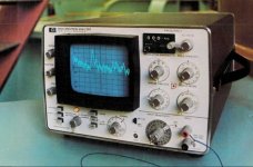
sweeping was done 30 yrs ago with a 141T Spectrum analyser with a LF tracking generator. Lacking the opportunity to borrow such equipment from work I plan to perform a scan using a modern oscilloscope I own (a Siglent 2104x) which supposedly can do bode plots. (not seen that yet), but it will provide a gain and phase diagram, and it has FFT software buit in. Hopefully that gets down to 10Hz. The output transformer was designed and bought for the end-tubes I am using (balanced 6550A) running in ultralinear mode. Optional I can switch it to triode mode. The PSU is traditional, with a tube rectifier, a 10H coil and lots of caps of different types. There is no hum in the output and it should have plenty power for the amplifier. The power transformer was specced by me and custom made (350V/350VA). As soon as I have reverse engineered my own design I will know more 🙂. Thanks for the tip using a cap in parallel with the resistor as dummy load. I was using a fat 4 Ohm resistor.
sweeping was done 30 yrs ago with a 141T Spectrum analyser with a LF tracking generator. Lacking the opportunity to borrow such equipment from work I plan to perform a scan using a modern oscilloscope I own (a Siglent 2104x) which supposedly can do bode plots. (not seen that yet), but it will provide a gain and phase diagram, and it has FFT software buit in. Hopefully that gets down to 10Hz. The output transformer was designed and bought for the end-tubes I am using (balanced 6550A) running in ultralinear mode. Optional I can switch it to triode mode. The PSU is traditional, with a tube rectifier, a 10H coil and lots of caps of different types. There is no hum in the output and it should have plenty power for the amplifier. The power transformer was specced by me and custom made (350V/350VA). As soon as I have reverse engineered my own design I will know more 🙂. Thanks for the tip using a cap in parallel with the resistor as dummy load. I was using a fat 4 Ohm resistor.
Yes, a schematic is the first step. Seems like you built a Williamson design with long-loop feedback (from the output terminals back to first stage cathode), so you might use that as a place to begin drawing the schematic. The second step will be to measure DC voltages throughout. This will point to potential "static" issues, which need to be addressed before tackling any "dynamic" (feedback stability, etc.) issues.
All good fortune,
Chris
All good fortune,
Chris
A side note: Spice is only as useful as the data it's given, so be prepared to measure some parameters of the output transformers that are not generally available (from anybody), and without which results are meaningless. These measurements absolutely can be done, but are often more effort than DIYers are willing to expend. GIGO.
All good fortune,
Chris
All good fortune,
Chris
HP at one point in time did have an audio Spec 'A. But it was stand alone, not a plug-in. I'll pull up the model number tomorrow.sweeping was done 30 yrs ago with a 141T Spectrum analyser with a LF tracking generato
It had very slick circuitry for an analogue Spec 'A, It fixed some of the problems related to 'Q' of the filter in the IF section of the analyzer circuit.
Nelson-Ross, a small company offered a very nice audio spec 'A that was in a plug-in that fit into the 141T mainframe,
We sold several 141T mainframes that way, I often went on demoes with the Canadian Nelson-Ross rep.
The sale of a 141T mainframe without RF & microwave plug-ins wasn't a lot of money but sometimes led to other opportunities.
HP had a special division that manufactured chassis & plugs-ins as complete but bare units & sold these to some outside of HP.
The Nelson-Ross audio Spec'A was an example of this. There was another group that built all the transformers, chokes & so on, See Paeco. 👍
@jhstewart9
https://www.hpmemoryproject.org/an/pdf/an_134.pdf. This is how I did it back then.
Did a sweep yesterday with the o'scope. Looked much worse than I could recall from '93. But it matches what I hear. Will have to redraw the schematic and start troubleshooting. Apparently the floating paraphase is gone, and I used a more standard phase (cathode/anode) splitter with the first triode as an amp. I think paraphase has unity gain and the second stage also did not amplify a lot. Maybe that's why it's gone.
JohanBE,
It will be fun to look at your schematic when you get it posted.
I remember when many RF spectrum analyzer and tracking generators combinations did not measure below 10kHz.
Start spur amplitude, phase noise, resolution bandwidths, etc., limited practical measurements below 10kHz.
HP had much lower frequency equipment to do tracking measurements.
And Tektronix had the 7L5 plug-in with tracking generator that also went to lower frequency too.
I have found that spot frequency checks from 20Hz to 22kHz from a test CD, and square waves can find most frequency response problems.
My test CD has a single sample time impulse, and a scope with an FFT can do a quick check from about 100Hz to 22kHz.
Most amplifiers are flat all the way from midband to the -1dB low frequency point, and from midband to the -1dB high frequency point (any design that has an actual resonance with a measure-able Q between those two frequency limits needs to be fixed (if it is not oscillating already).
Frequency response specifications of some Hi Fi amplifiers gave some marketeers a way to make their amp 'appear' better than other amplifiers that actually had the same frequency response:
A given amplifier could be specified one of two ways:
+/- 1 dB from 20 to 20kHz
+ 0 dB to - 2 dB from 20 to 20kHz (with the midband frequencies at 0 dB).
Both have frequency response limits that are 2dB apart, no matter which of those two ways you state the specification.
Last edited:
From your description it sounds like your original build was a Williamson circuit with a different front end.Each monoblock is composed of three stages, a floating paraphase input stage which delivers two 180 degree out of phase signals. It uses a 12AX7-WA milspec double triode. The second stage is a double triode (6SN7GTA) which just amplifies the 2 signals for the endstage, a pair of 6550A's in ultralinear mode. The output transformer is tailored for the 6550's in UL mode. I recall the amp working stable (no oscillations)without feedback circuit, and covering 20Hz-20kHz. But since i recall experimenting with FB I'm not sure how linear the amp really is.
Then the front end was modified to the Williamson circuit later.
A post by someone else already references the Williamson circuit. The Williamson is known to be only conditionally stable when NFB is used.
Many building this cct tried to follow Williamson's original design which used 20 db NFB. But the OPTs used sometimes did not meet Williamson's Spec.
And along the way more gain was added by using an Ultra Linear OPT as suggested by David Hafler & Walter Keroes in an Audio Magazine article.
Another problem in the early builds was the power supply bypassing. 100 micro F electrolytics were not common on the market as now.
The result in some amplifiers the power stage disturbing the B+ to the earlier stages to an extent that stability was compromised.
This was sometimes called 'motor boating'.
The result was many amplifiers built that were somewhat unstable. The problem were often difficult to resolve with limited test equipment.
PP triode output guarantees a good low frequency result. But the high frequency end of the audio spectrum needs an outstanding OPT,
no matter how it is driven. Leakage Reactance always gets in the way. Imagine trying to push a rope up a hill, next to impossible.
Still interested to see the schematic of your amplifier tho. 👍
JohanBE, thankyou for your reference to the HP 8556A. Besides the Test & Measurement Product Groups,
HP had several other Product Groups. Some of us got moved to cover these, in my case it was a move to Semiconductors & related devices.
I also got into something called Digital Signal Analysis (sometimes referred to as Paralysis). That would be Auto & Cross Correlation,
PRBS Generators, Signal Averaging & on & on. I completely missed the Audio spec A capabilities of the 8556A. That happened after the move.
The Audio Spec'A that did come to mind is the HP 3580A. It is a self contained unit, not a plug-in.
And technically a much simpler solution than the 8556A.
Still looking forward to your schematic. 🙂
Attachments
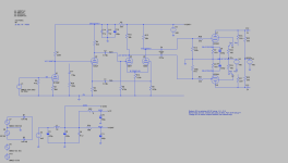
I think I have every wire traced back now. The amp uses a JAN6189W as the pre-amp/cathodyne phaseshifter. The next stage is a JAN-6SN7WGTA in common cathode mode followed by the endstage: 2 JAN-6550A in push-pull. And not in ultralinear as I first thought. It has a switch to toggle between tetrode and triode mode. The triode mode does not match up with the LTspice simulation. Seemed like a good idea at the time as they say. But need to look into that later.
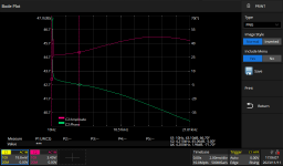
1Wrms output (8Vpp over an 8.2 Ohm resistor) is reached with about 50mVpp input. This represents a voltage gain of 44dB. The measured charts are close.
I have attached the schematic and two sweeps. I also have CSV files of those sweeps (upload not permitted).
So the sweeps don’t look very bad and (to me) don’t explain why there is virtually no bass to be heard. I think I’ll have to do another sweep and measure across a real speaker.
All of this has been measured without feedback circuits. Unfortunately I do not have enough data on the output transformer (6k6, 115mA is all I know) to start a simulation with FB from the output terminal.
So what is the best way to proceed here? I could probably start playing with a feedback circuit (not simulated). But how much feedback can I/should I afford?
Attachments

The problem I find with spice is it doesn´t handle 6-12W pentodes strapped into triode models. (Unless someone can direct me on this). Previously, I drew fresh graphical charts with them in that configuration then roughly assumed the nearest listed tube equivalent in the library, all rather laborious. That was nearly 15 yrs ago. My eyes have aged but I´d do anything for ease...This is a great primer for easing into LTSpice ... Angelfire: Learning LT Spice - Lesson 1
BB
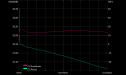
Even though the triode sim is not really working (using the 6550AT model), in reality things seem to work. Sweep attached.
Attachments
Last edited:
You can't just sub in 2 x 3.3k resistors instead of the output transformer. There is plenty of information on DIYaudio about modelling transformers using linked inductors, or if you post the .asc file I'm sure someone could add one in for you. It won't match what you have exactly but will at least get the output stage working in the correct manner.
I'm aware. A resistor by no means equals a coil. But with the info I have (only primary and secundary impedances and an operating current) I doubt that anyone can create a reliable OPT model. So the resistors serve no purpose other than closing some DC circuit. What I'm after is optimisation of an existing amp, so lacking a working simulator I might also work the old-fashioned way. (A bit of calculation, trial and error and just using test-equipment to measure the results). That is how I built the amp. But the simulation was nice for the first two stages, and showed there are improvements possible. I just started using LTSpice a couple of days ago, my first simulator ever 🙂 .
- Home
- Amplifiers
- Tubes / Valves
- My old 1993 tube amplifier and 2023 SPICE