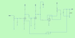
Hi, Please help me understand why people use SRPP, CCDA, cathode follower etc., while not using the attached configuration with two triodes in series and GNF.
This is also the one that when simulated gives me the lowest THD among all the previous ones that I have simulated, the one that has the most linear frequency response and also the highest input sensitivity.
(Let us use ECC83 only, pls)
This is also the one that when simulated gives me the lowest THD among all the previous ones that I have simulated, the one that has the most linear frequency response and also the highest input sensitivity.
(Let us use ECC83 only, pls)
Attachments
You have lots of loop gain inside the FB loop, which explains the "good" properties, whilst a follower on its own has just the internal gain of the active device.
However, I suspect that your transformer has minimal parasitics in the sim. The reality would probably be less shiny, and stability issues could surface
However, I suspect that your transformer has minimal parasitics in the sim. The reality would probably be less shiny, and stability issues could surface
Simplicity & a lot of us are not seeking ultra high specs. If you want all that use an opamp.Hi, Please help me understand why people use SRPP, CCDA, cathode follower etc
I have seen plenty of schematics using a similar architecture for UL single ended pentodes, tetrodes etc. amps. It is not rare at all. But many tend to use very linear output triodes and no negative feedback. Some of those triodes are driven to A2 to get more power, requiring a more powerful driver.
And, imagine how boring would it be if everybody uses the same tried and tested circuit 🙂
And, imagine how boring would it be if everybody uses the same tried and tested circuit 🙂
About (Let us use ECC83 only, pls), I just noticed it. No, I have never seen an SE with two ECC83s.
This is the only reason I could see. Maybe that so large GNF (3 tubes + OT) gives too much phase rotations, thus risk of oscillation? But still searching, maybe old books. Strange nobody has never tested this, which appears the simplest and easiest....stability issues could surface
The circuit is not good for what we want from tubes , especially from a single ended ... Huge gain open loop and a lot of negative feedback . Big possibility of oscillation or instability . Not good for hi-fi or guitar amplifiers either .
Strange is that you could think that such a simple circuit wasn't tested before ... of course can work but is not very desirable .
Strange is that you could think that such a simple circuit wasn't tested before ... of course can work but is not very desirable .
Last edited:
Thank you, but still looking for someone who anyway tested it. The fact that there is no reference, means it doesn't work (because oscillating) or work bad (bad sound). That's my only conclusion. The only reference I found was this, but the loop is on second tube and he uses a much lower gain triode. And simulating it gives much more higher THD than mine. But it doesn't explain why was not tested on the first stage and why not with the original 12AX7 (6N2P).Strange is that you could think that such a simple circuit wasn't tested before ... of course can work but is not very desirable .
https://www.audiovalvole.it/amplifi...ng-a10/reisong_a10_audiovalvole_stage2_01.png
https://www.audiovalvole.it/amplificatore-valvolare-cinese-reisong-a10.html
The purpose of this amplifier is somewhat different, it is for testing heat-management:
https://www.diyaudio.com/community/...rging-a-e-pcl82-amplifier.351667/post-6134055
But it bears some similarities, except it is two-stages only. Yet, stability issues were not that straightforward.
You have three differentiating poles (2 caps and the transformer); avoiding motor-boating is probably possible, but it is not going to be easy
It even (sim-)works. Nothing optimised, just put together the usual resistor/voltage values for a 12AX7 🙂

I'd worry that without compensation it could oscillate at RF. The acid test is building it for real.Hi, Please help me understand why people use SRPP, CCDA, cathode follower etc., while not using the attached configuration with two triodes in series and GNF.
This is also the one that when simulated gives me the lowest THD among all the previous ones that I have simulated, the one that has the most linear frequency response and also the highest input sensitivity.
(Let us use ECC83 only, pls)
Here below I found a reference. Same scheme of ours simulated BUT WITHOUT feedback..... It is for a guitar, so it means non-hifi. And infact without GNF the sensitivity drops to 15mV at the expense of a huge THD.It even (sim-)works. Nothing optimised, just put together the usual resistor/voltage values for a 12AX7 🙂
View attachment 1235921
https://miro.medium.com/v2/resize:fit:1100/format:webp/0*7O1yuvpRdPro_C4F.jpg
https://medium.com/audioxpress/you-can-diy-build-a-single-ended-guitar-tube-amplifier-40f23353dfb6
And, imagine how boring would it be if everybody uses the same tried and tested circuit 🙂
Off topic: That's the problem with solid-state class-(A)B amplifiers: many people designing the same old circuit over and over again.
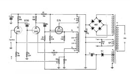
...and finally this is from 1958 : two ecc83 and one
It uses several loop of GNF and the OT is quite complicated (I cannot reporduce), but the overall concept should be directionally correct. The article says 0.3% THD at 9W!
😱
It seems that you discovered America again 🙂 , secondary used in the cathode feedback loop has nothing to do with your setup .
Last edited:
The schematic in Post # 1 can very loosely be considered as a single ended Williamson push pull amplifier.
That is because it has global negative feedback, and . . .
3 low frequency poles:
Two RC couplings from plate to grid
One output transformer with primary inductance.
Get your low frequency poles adjusted, or expect motorboating.
And, watch out for high frequency oscillations too, there does not seem to be a dominant high frequency pole (other perhaps than the output transformer).
Build it with real output transformer and real wiring.
Simulations are often 100% correct, other times you have to do some adjusting of real circuits.
- Home
- Amplifiers
- Tubes / Valves
- There are no references on the web, so what's wrong with this simple setup?

