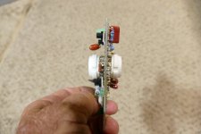
After exactingly populating Pete Millett's Mighty Midget board, I have made a fundamental error and soldered the compactron 6T10 sockets upside down.
We are talking about 12 pin sockets here so the process to correct this error does not seem simple.
I am planning to:
(1) snip the pins on the socket side
(2) order new sockets
(3) desolder the stumps of the pins using a pump and braid
(4) solder in the new sockets with the correct orientation
All with the hope the pads don't lift and I can get enough solder out of the pads to make the room for the new pins.
Does anyone have tips or a smarter approach?
Last edited:

I have done the same thing, and there is sufficient pliability between the pins in the socket and the board to apply a lever under each one and unsolder and move it a fraction of a millimeter at a time, working around the pins, and slowly ease the socket out. (That was only 9 pins though).
However there is a great trick I learned from youtube, shared from somewhere here at some time, where you embed some thick gauge wire around the circumference of all the pins, lay on the solder, then heat the thick wire so the heat is conducted around all the pins and the socket can be easily removed.
Remove a multi pin connector with soldering iron
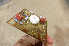
There can only be one reason that this exists. I didn't even bother to remove the wrongly placed socket, but this was only a test board. It served its purpose and has lived in the "box of dead circuits" ever since testing was completed. It was the test board that led to the development of UNSET technology.
Attachments
You can use a solder sucker tool and go pin by pin. Once you’ve gone around once put a thin screwdriver between the socket and the board to use as a lever heat the pins up several in a row and apply light pressure to the socket outward to slowly go around the pins and work it out. It takes practice and can end badly if you force things to hard or quickly. Putting a new socket on the proper side leaving the wrong one in place is a good enough fix if you can get all pins to connect well via solder. I would use a meter to check the connection between corresponding pins on both sockets to ensure good contact with the pcb.
Thanks everyone, it is good to have the various techniques in a single thread for future solder slingers.
Pete Millett kindly gave the following suggestion:
I find the best way to remove a socket is to carefully clip all the leads one by one with a diagonal cutter on the socket side of the PCB. Then using a soldering iron and needle nose pliers pull out the remaining lead stubs one by one. Then, a desoldering pump and/or solder wick can clean out the holes.
If you do it that way make sure to cut the pins as long as possible so you can get a grip on them and have room to heat them that is not right on the pc board so you don’t overheat or scorch it. Once the pins are out go around the circle with a solder sucker pin by pin. The secret to successfully cleaning out te holes is to add a little solder to the hole and then suck it out. They work better when they have something to grab on to. The extra solder flows the rest of the solder out!
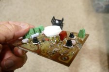
Yes, since that's where it should have been installed in the first place. The wrongly placed socket on the back side causes no issues as long as you don't put a tube into it.Clever! So you just soldered in the socket on the reverse side and that was it?
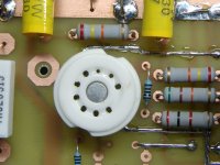
I have also used Pete's cut each pin, remove the socket, unsolder the remains of the cut pins from the board, then clean out the holes with a solder sucker method. In my case I am usually replacing sockets that are worn from too many insertions. I once found a socket that was poorly made, AFTER I had soldered it into the test board that became the first Tubelab SPP. I had to remove a few parts before I could cut this one out.
Attachments
I have been in a similar situation with stuff like this. I agree with trying to get as much solder out of the pin socket as possible, but here is a twist. I found a product called 'Chipquik'. It is essentially cadmium that is easier melted into the solder joint. Since the melting point of this product is only 200F, it will mix with the solder making the solder liquid for a longer time. Using solder braid it sucks into the wick like water. It is equally impressive with a solder sucking gun or other device. Best part is, it doesn't take so much heat to get the job done and you will not lift traces in the process. I am sure glad that I have it at my bench.
These little devices have been the backbone of electronics rework forever. Replacement tips are readily and cheaply available:
https://www.edsyn.com/product/DS017.html
All good fortune,
Chris
https://www.edsyn.com/product/DS017.html
All good fortune,
Chris
- Home
- Amplifiers
- Tubes / Valves
- Desoldering compactron sockets