Altec 1202a, different CDs?

Looking at buying a pair of 1202a speakers with 422 woofers (kinda like a 418B) and 807 CD’s on 811 horns. The two 807 drivers are different, one black an the other green. They are not quite the same, one is an 807-8A, the other 807Z and the witing terminals on the latter look ‘strange’. Makes me wonder what I’d be getting - Thoughts ?

Idea is to eventually re-use for mini Vott.

Attachments

  • IMG_7020.jpeg
    IMG_7020.jpeg
    42.3 KB · Views: 79
  • IMG_4980.jpeg
    IMG_4980.jpeg
    318.3 KB · Views: 88
  • IMG_7019.jpeg
    IMG_7019.jpeg
    59.2 KB · Views: 69

Can someone help identify what circuit was removed in the MkII version of the ARC SP10 preamp?

I recently acquired an Audio Research SP-10 preamp, specifically the well regarded Mk2 version. I immediately noticed a large bare area in the middle of the main circuit board, that clearly was populated in the prior revision. Attached are pictures of the Mk1 and Mk2 boards, as well as the schematics. I'm trying to work out the purpose of the removed circuit. I'm used to ripping out large seconds of code when optimizing software projects, but I've never seen it in a circuit design before!

Attachments

  • ARC_SP10_top-1.jpg
    ARC_SP10_top-1.jpg
    87.8 KB · Views: 142
  • ARC_SP10MKII_top-1.jpg
    ARC_SP10MKII_top-1.jpg
    79.3 KB · Views: 144
  • ARC_SP10_manual_schematic.pdf
    ARC_SP10_manual_schematic.pdf
    5.3 MB · Views: 170

Anyone had this problem?

Have you ever had a tube where the socket was low so the tube poked thru the lid of the amp with the metal top plate about a third of the way up the glass of the tube? Did it cause you grief? I believe it is ruining the day of a D3a on my 300B SET amp. I grew tired of looking at the mickey moused wiring and other "features" of my beloved amp so I made a new circuit board but the D3a sockets were not as tall as the previous board and I think it is causing some weird noise. Anyone else ever have this happen?

Jeff

Transistors stuck to heatsink

Hey,

Recently picked up two amps in a trade.

Neither are working 🙂

(I was aware of them not working when I got them)

One is an Adcom GFA-5500, and the other is a Krell KSA-200.

The Adcom was something the that he threw in as he was doing spring cleaning, which was very kind of him!

I’m starting with the Adcom, and I’ve pulled it apart, but can not get the transistors to release from the heatsink?

In order to start working my way through the amp boards, I need to get them off the heatsink.

Any thoughts on how to get them to safely release?

Thank you in advance for any thoughts!

Per

Peavey KB2 issue

i'm decent with most tube circuits, but a good bit out of my depth here, and hoping for some guidance from you kind folks. a friend brought this in and i figured this would be a good opportunity for me to learn more about chip circuits!

the initial complaint was large amounts of distortion especially in the low end, increasing with increased input volume, as well as distortion when she tapped on the top of the chassy. i checked all the solder joints, found none cold or broken but still reflowed and added a bit to any that seemed even a little suspect.

plugged it in to test, and hoo boy it's doing some strange stuff. any signal fed to any of the inputs results in a full-blast, extremely distorted output at the speaker. this is with the volumes set at 0! when the volume is turned up, it gets even more distorted!

note that all DC voltage measurements are measured with the black lead to the heatsink, which is connected to CGND.

the +/- 15V rails seem to be fine, measuring 14.92V and -15.09V throughout the amp. but the +/- 20V rails are more like +/- 37V! pulled the connector from the transformer, and it measures about 28.48VAC per side, so i'm a bit confused as to how that's supposed to drop to +/- 20V even with a heavy load.

i plugged a little patch cable into the inputs and got some weird readings there too. channels 1 and 2 both initially read at 14.47V on the sleeve connection! but then drop to around 7V after a few seconds. the tip connection slowly climbs up from 0 to about 7V after maybe 30 seconds, with an enormous buzzing even with the volume turned all the way down. channel 3's sleeve is fine at 0V, but the tip starts at about 13.6V and very slowly decreases from there.

checked on the 8 JRC4560D's on the preamp board, i'm still learning about op amps and am not entirely sure how these are supposed to measure, but besides the +/- 15V present on pins 4 and 8 as mentioned, they seem to measure similarly in two groups. U1-U6 all measure about 14.4V on pins 1, 2, 6 and 7, though pins 2 and 6 usually seem to start out at about -13.5V, then jump to the 14.4V after a second or two with a loud pop. pins 3 and 6 (ground connections) make an ungodly loud pop and buzz, and either slowly climb to around 7V, or fall from around 3.5V. but U7 and U8 measure 0V all around, with only a slight buzz when pins 2 and 6 are probed.

i'm thinking this issue has something to do with the ground connections, specifically GND1-3, as 4 and 5 are the ground for U7 and U8 and seem to sit fine at 0V. but i'm very unused to amps where different ground connections are isolated from each other to various extents, let alone where the ground for the entire amp is floating (CGND is actually not connected to the chassy as far as i can tell, as the green wire leading to the earth ground nut is only connected to the rest of the circuit through C55 which only connects to the primary), and i'm very unsure as to where to look next. thanks for reading, i'd be grateful for any guidance at all!

Attachments

Neutrik combojack connect to 3.5mm TRS jack

Hi,

Im having a hard time wrapping my head around the neutrik xlr/trs combo jacks and if they can be connected for my usecase .

In my rack I have a 3.5mm trs input jack that can be either line or mic level (it’s an ATEM extreme switcher) . My plan is to break this out into a patch panel where I have two combo jacks .
What I want to achieve the following

1. Plug in two balanced XLR then these should combine to LR on a 3.5mm trs plug
2. Plug in two balanaced TRS then combine as for 1.
3. Plug in two unbalanced TS , use L and R to 3.5 mm jack directly
4. One stereo TRS , just patch LR channel as for 3

Is this setup possible to achieve without using a mixer?

Unusual Omni directional Wharfedale Super 8

Hi everyone
not been here for some while so please excuse me if I use wrong posting etiquette. I bought a pair of Wharfedale Super 8 RS/DD drive units and the units shown in the attached pics . I have not seen these before, they look original with metal cone and what looks like original covers. Can anyone tell me what they are? I think they are used in some sort of omni directional cabinet but hopefully some one can tell me who made them (Wharfedale?) , originality and if still worth using?
Thanks
mouse

Attachments

  • IMG_20230927_140622266.jpg
    IMG_20230927_140622266.jpg
    518 KB · Views: 122
  • IMG_20230927_140638671.jpg
    IMG_20230927_140638671.jpg
    826.1 KB · Views: 112

Which DAC hat for Phono

So a friend wants to gift me a pie and dac hat.
My only issue is what ever I use Id like to have the ability to listen to my Hitach HT350.
So is there any dac hat out there which supports Phono in.
Or can I setup a custom EQ curve to simulate the RIAA standard.
I did find a Bluetooth dac which supports phono in for like 100$. But he seems convinced I need a pie setup.

For Sale Lundahl Audio transformers LL1584-3FX3MX and Signal choke LL1964

Lundahl LL1584-3FX3MX Audio transformer isolation unit​

https://www.lundahltransformers.com/wp-content/uploads/datasheets/1584_x.pdf
In-line XLR units with integrated high level audio isolation transformer.
For breaking up ground loops in audio systems and for balanced-to-unbalanced conversion
The XLR inline transformer unit LL1584 is designed for breaking up ground loops and for balanced-to-unbalanced conversion in mobile or stationary audio systems. The unit is magnetically shielded and contains a medium impedance isolation transformer LL1584, with LF saturation above +17 dBU @ 50 Hz.
The two ends of the units are galvanically isolated from each other.

2 units available. Retails for 180€ each. Asking 130€ for the pair + PP fees + Shipping

Lundahl LL1694 Signal Choke​

SOLD​

Compact choke for audio applications.


NAD 2400 - CAPACITOR MOD

Hi, I have a nad 2400 amplifier that I use with a tube preamp that I built. The preamp has output capacitors.
I enter the nad via the LAB input which bypasses the first operational amplifier. The first thing the signal encounters is the 33uf c401 electrolytic capacitor. Do you think I can delete it? I don't use other amplifier inputs.

If I remove the c401 do I have to leave the resistors r402 and r402?

Thank you

I attach the schematic

Attachments

  • 378556116_1719488051899676_3375539509208954118_n.jpg
    378556116_1719488051899676_3375539509208954118_n.jpg
    195.3 KB · Views: 102
  • nad_2400_power_amplifier_page-0007.jpg
    nad_2400_power_amplifier_page-0007.jpg
    346.2 KB · Views: 89

Subsonic/High Pass Sallen-Key Network with variable Cut-Off Frequency and Potentiometer instead Rotary Switch for Capacity Selecting

Low pass Sallen-Key filter with variable cut-off frequency there are often to find - go to first attachment.

In case of filters with high pass character and variable cut-off frequency in commercial active crossover network devices I find always switches (for variation the values of C1 and C2 in second attachment) but never a stereo potentiometer for R1 and R2.

The reason therefore is the fact, that the character of filter isn't constant over the entire angle of 270° rotation as long as the potentiometer is a linear version.

There was sometimes describe an approach (with schematic) in an Elektor (Elektuur) article (80s or 90s) that solved this problem by adding different resistors to the used stereo- resp. tandem-potentiometer for R1 and R2 (both serial resistors and parallel resistors - but in different kind for R1 and R2). These additional resistors made it possible to use a potentiometer for R1 and R2 in the second attachment without affecting the characteristics of the filter over the intended frequency variation range.

This is from my view much more better and more easy to realize than the variation of C1 and C2 (from second attachment) with stepper character switch.

Who can upload this article from elektor ?

Thank you very much.

P.S.: The attachments are from here:
http://www.stefanv.com/calculators/hp41c_sallen_key.html

Attachments

  • 15CMa.png
    15CMa.png
    6.4 KB · Views: 235
  • highpass.gif
    highpass.gif
    1.7 KB · Views: 139

Absolute newbie...please be simple and kind!

I have what I believe is a subwoofer crossover (?) and would like to know if I can convert a Sony subwoofer (made for computer use) to an all-purpose sub using the crossover unit (see pics). As I said, I'm a novice so my knowledge is quite limited as far as the technicalities are concerned. This is just a hobby project I thought I'd try my hand at.

Attachments

  • IMG_0014.jpg
    IMG_0014.jpg
    250.3 KB · Views: 139
  • IMG_0015.jpg
    IMG_0015.jpg
    206.7 KB · Views: 321
  • IMG_0764.jpg
    IMG_0764.jpg
    495.2 KB · Views: 129
  • IMG_0765.jpg
    IMG_0765.jpg
    680.4 KB · Views: 128

AlephJ diyAudio amp

SOLD

Thinning out the number of amps I have. I built each of the amps for sale for personal use and am selling for below cost of construction.

Basic details: Deluxe 4U chassis. Antek AN-3218 transformer, Toshiba JFETS. Multicap RTX capacitors, PRP metal film resistors, Silmic II electrolytics, Panasonic power resistors, CDE 380LX 47,000uF 50V PS capacitors, Cardas and Kimber wiring, EAR Isolation feet. Functions perfectly. Will be carefully packaged for shipping.

$775 incls shipping within Continental US. Payment via Paypal.

Attachments

  • ALEPH J_0611.jpeg
    ALEPH J_0611.jpeg
    585.5 KB · Views: 182
  • ALEPH J_0612.jpeg
    ALEPH J_0612.jpeg
    552.7 KB · Views: 156
  • ALEPH J_0613.jpeg
    ALEPH J_0613.jpeg
    474 KB · Views: 185
  • ALEPH J_0614.jpeg
    ALEPH J_0614.jpeg
    475.4 KB · Views: 174
  • ALEPH J_0615.jpeg
    ALEPH J_0615.jpeg
    485.1 KB · Views: 173
  • ALEPH J_0616.jpeg
    ALEPH J_0616.jpeg
    420.8 KB · Views: 162
  • ALEPH J_0618.jpeg
    ALEPH J_0618.jpeg
    390 KB · Views: 179
  • ALEPH J_0619.jpeg
    ALEPH J_0619.jpeg
    768.5 KB · Views: 185
  • Like
Reactions: 6L6

Are These All The Same RN55C Resistors? (Marking Codes & Colors)

Years ago I bought some surplus resistors and in one bag there are three different colors of 30.1k resistors. I assume the original users mixed different brands or perhaps different age (era/marking scheme)? But I am not 100% sure.

I have figured out some of the marking codes and I believe that these are all RN55 (with one possibly being a related similar type).


I interpret the markings to mean "C" = 50 ppm, "B" = 0.1%.

However since they are all marked differently and are even different colors I would like to double check with someone who recognizes the marking scheme.

The first type are DARK Blue and are marked:
Line 1: 91637 (From searching datasheets this might be DALE ERC55?)
Line 2: 904H (Perhaps a date code plus "H" = ???)
Line 3: 3012 (30.1k Ohm)
Line 4: BSCJ (I am guessing B = 0.1%, S = Solderable and CJ is a reel/packaging code. It looks like a Dale part number but does not seem to exactly follow current Dale datasheets and is not marked DALE on the body.)

Can you confirm that these are "C" = 50 ppm, "B" = 0.1%?
What is the vendor and series? I assume DALE but not RN55. Perhaps ERC55?


The second type are Light Brown and are marked:
Line 1: DALE
Line 2: 9651J (Date code plus JAN/Joint Army - Navy)
Line 3: RN55C (RN55, "C" = 50 ppm)
Line 4: 3012B (30.1k Ohm, B=0.1%)

So these look like RN55, "C" = 50 ppm, "B" = 0.1% unless I am wrong.


The third type are LIGHT Blue and are marked:
Line 1: P (Does this signify a different brand/vendor?)
Line 2: RN55C (RN55, "C" = 50 ppm)
Line 3: 3012B (30.1k Ohm)
Line 4: B (B=0.1%)

So these look like RN55, "C" = 50 ppm, "B" = 0.1% unless I am wrong.
What does the P signify (different brand)? Why light blue instead of light brown like the second type? (Brand?)


I also would like to figure out the bag of light blue 20k resistors which have four bands for 20k value (Red Black Black Red) and then gap with a "2" printed on the light blue lacquer and then a violet band. Anyone recognize what these might be especially with the little "2" printed between the four value color code bands and then the fifth violet band? I have never seen a little "2" printed on a resistor before like this. At first I thought it was a brand symbol but under the microscope it is a little 2. The fifth band is violet = 0.1%.

So it looks like 1/4W 20.0k 0.1% but what does the "2" mean?

8" full range in vented box, paired with a woofer/sub?

hello,
i want to pair a 8" full range vented enclosure (around 65 liters) with a woofer/subwoofer (can be any size). is this not a good idea? most of these WAW/FAST configurations i have seen have full range that are 5" or smaller, with a 6-12" woofer. why not use a larger full range ?
the full range is to be used inside a lively cafe, and then paired with the woofer/sub for outdoor events/partys (around 30-50 people). i really want the full range to be vented bc i like the look of it, and the woofer/sub would be in a separate cabinet.
for the 8" full range driver i was thinking of using jbl 328c (ojas fan), but i cant find the detailed TS parameters for it. otherwise maybe the dayton audio PS220-8 8" neo driver, or the SB Acoustics SB20FRPC30-8" (amazing reviews, but the price is so low its makes me doubt it). i have previously used lii audio fast 8", also vented enclosure in around 65L, but the highs were piercing in some frequencies. the bass was good though, but never fully tested for large outdoor parties.

for the woofer/sub i have no idea, i cant even figure out if this sort of a combination makes any sense or if it would be a woofer or a sub. does anyone have any advice on which it should be, and any driver recomendations? should this also be ported or is that up to me? at what frequency would i xo?
i cant find many configurations pairing a 8" full range with a woofer, except for lii audio which has a configuration of 8" full range and woofer, but it is on an open baffle. maybe this configurations (8" with sub/woofer) doesnt exist bc the full range already covers the lows? should is be a subwoofer? i thought for a outdoor event the lows would get drained out and hence would want to pair it with a woofer/sub.

Waveguide to suit Peerless HDS/Scan-Speak D2608/91300

New_Waveguide_Front_Tweeter.jpg

Click to enlarge...


BACK IN STOCK MARCH 3RD, 2021

To Suit Tweeter - Peerless HDS/Scan-Speak D2608/91300

AUD $190 per Pair including Air Postage anywhere.


Please click this link to Pay and Order: PayPal.Me

To suit Peerless HDS/Scan-Speak D2608/91300 - possibly could adapt to another similar size 1" Tweeters, but is a very precise fit to the specified tweeter.

You need a very precise fit in the 'throat' area and only a custom-made Waveguide will do that perfectly:

810921.jpg


This is a Special Tweeter and would be great even if Scan-Speak sold it at 3-4 times the price!


Click the image to open in full size.

Waveguide_3D.jpg


3D rendered image.

Payment via PayPal address joeras@customanalogue.com is OK. Also, in Australia, bank transfer is available.

The material is known as ACETAL HOMOPOLYMER and with a slightly roughed up surface, which means it could be sprayed any colour with a $10 can of enamel.

Diameter: 148mm, to suit 150mm cut-out.

My Industrial Designer's comments: Acetal combines lubricity and wear resistance with the stiffness and strength needed in parts designed to replace metal. It is a highly-crystalline polymer that has high stiffness and strength without the need for glass reinforcement, allowing for thinner and lighter part design. It offers outstanding low and high temperature performance, good colorability, and good mating with metal and other polymers. About the best 'plastic' there is.

Edit: I was later informed that this material is also known as Delrin.

A suggested starting point of Crossover:

Waveguide_Xover.gif


This gives a gradual 1st order electrical slope gradually going into 5-6th order slope. Excellent phase characterists.

Below: Elsinore Mk6 Loudspeakers using this Waveguide. Click the image to open in full size.

Below as used in Elsinore Mk6.

Oct-2015_405W.jpg


________________________________________________________________________________________________

Been asked to post some responses:

926997d1614483591-elsinore-project-thread-waveguide_responses-gif


Some notes: Red is online and the dip at 1900Hz can be largely ignored, same goes for the peak at 3KHz and it appears only when dead-on to the tweeter axis. The best response and the one that is recommended is the Green which is 15 degrees off axis and is also the best listening angle between 10-15 degrees. Blue is 30 degrees off axis.

The responses are typical with Waveguides and as 'gain' below 10KHz and peaks at 3KHz, the recommended crossover frequency. You can of course cross over lower than that, but you will be trading off distortion with bandwidth.


The crossover must EQ the response and looking at it, the flattest off axis response (15 degrees) is when 92dB/m-SPL (or lower) is chosen.

Waveguide_Responses-15-Corrected.gif


Cheers, Joe

PS: I often get asked, "why this tweeter?" While it was initially sold under the Peerless name, it was always a Scan-Speak tweeter and was always Made in Denmark like all Scan-Speak drivers. Because of a strange set of circumstances we have a tweeter that would be good value even if sold at 3-4 times the price. It is not perfect, but it has a set of attributes that translates into a sound quality that is rare, but only when attention to detail is made. It also has the near perfect attributes to be a Waveguide tweeter. This can be used to lower the crossover frequency (increased bandwidth) and that has certain attractions. But using a crossover of around 3KHz and the suggested high-pass filter above, the reduction in the kinds of distortions most disliked by the ear, but also measured, is remarkable. In the Elsinore Mk-6 loudspeaker, owned by Brian Gurr in Auckland New Zealand, who is somebody who builds electrostatic (and also does rebuilds), this Waveguided tweeter, according to Brian, competes with top class electrostatic speakers in the very upper midrange (the most critical part of the human perception) and treble. I can't think of higher praise than that.

Below is the response used as per above suggested high-pass as used in Elsinore Mk-6, a speaker where absolute low distortion and controlled phase is the object (there is a lot to learn in the EL-6, if I may say so):

Waveguide_Xover_Response_EL-6.gif

Using Many Small Signal Transistors Paralleled in place of one output Transistor

Hello everyone,
As you may have guested, I have some unusual ideas when it comes to electronics.
Well hear's another one.
A few months ago i decided to see if instead of using the usual power / driver transistors in my amplifier, I could Parallel small signal transistors (example BC546) together with low value resistors ( current sharing ) and see what the effect would be.
so i parallel 20 BC446's and 20 BC556's together to take the place of the normal output power transistors and 3 each paralleled in the same manner for the driver transistors to see how it would sound.
As i decided to run the amplifier at 16volts rails and only a single + and - supply with a output eletro capacitor mainly to see if it would work.
It did and the sound was ok. it sounded a bit tinny and i used it for a couple of days before going back to my old setup.

In the upcoming months i plan to build a set up with 100 signal transistors in place of one power transistor and run it with a split supply of 28v / 28v and see what the effect would be on the sound.
i am interested in seeing how hot each transistor gets and i may even try the idea with the JLH 10Watts CLass A Design and see how hot the transistors get in a Class A.

Has anyone else already tried this idea and if so how did it go?

Time to cut my losses on this project?

Hello everyone, I started a thread about this project several weeks ago, and the responses were very helpful, thanks. I'll try to be as concise as possible to present my dilemma.
This is my first scratch build. The goal was to create a pair of speakers with minimum 94db sensitivity using a coax driver, to pair with an Alan Eaton SET45 amp, which is the epitome of "flea watt" at <2 wpc.
I ended up choosing the Radian 5210, a 10" coax with a very good reputation. Even though it looked anemic below 100hz, even 150, I thought with proper port sizing and fill I could get it to work and be pretty solid from 50hz and up, and since I use a sub I wasn't worried about these being bass monsters.

I've worked very hard on this project, all the while thinking that the satisfactory response curve was there to be found, if only I could dial things in and measure them well. Yesterday I did another round of measurements, as I'm getting more competent with REW and wanted to start clean and really see what's happening with these speakers.

Below I've posted the latest results, showing impedance and T/S parameters, and also the results of my summed port (compensated -6.4db) and nearfield woofer. The overall speaker consists of the Radian 5210 coax in a 3ft/cu box, with a 4" port tuned to 42hz. The problem is the rolloff starting at 170hz, eventually losing about 7db from 60 hz down. I don't know of any way to compensate for this without a correction network that would attenuate the woofer response above 80 hz, which means I'd lose 6-8db in sensitivity (woofer is 96db sens), and a catastrophic loss of 16db +/- for the tweeter, which is 105db. I guess it's basically a baffle step correction, but I don't have the headroom to lose that much.

I realized yesterday that this probably just isn't going to work, because you can't get blood from a stone, and that driver just doesn't want to go low, and it was my rookie mistake to think that I could trick the system by tuning the box and port to prop up the response below 100hz.

So I'm asking the community, am I correct in my assessment, or is there something I'm missing? I'd rather start over and cut my losses than keep beating my head against the wall.

Thanks in advance,
Bryan
IMG_5477.jpeg
IMG_5475.jpeg
IMG_5476.jpeg
IMG_5453.jpeg

Natur Aura Purpleheart - 7-driver Open Baffle build (for BAF '23)

This thread is about my latest build, the Natur Aura.

I completed these just in time to demo them at Burning Amp ‘23. I am proud to say that these got many compliments including a couple “best in show” comments.

Details provided below for the ambitious DIYer.

DSCF6557-edit.jpg


Summary
A monument to sound.

Aura is an open baffle loudspeaker crafted from a solid slab of Purpleheart wood.

Each side features seven metal-cone wideband drivers from Esoteric Audio Devices in Sweden. We selected these drivers for their impressive detail and realistic presentation of vocals and acoustic instruments.

The narrow and frameless open baffle design yields excellent clarity along with a large, full-bodied sound. The dipole radiation pattern minimizes room reflections. This design acts as a dipole throughout the full frequency range. Dipole bass is especially clean with a natural-sounding rolloff.

The crossover is the result of much experimentation. Our goal was to retain as much detail and clarity as possible, while minimizing the harshness that can be a problem with metal cones.

Aura builds on our expertise designing passive open baffle loudspeakers. The final design is the result of hundreds of hours of prototyping, tweaking and critical listening.

Specs
  • Seven driver passive open baffle design.
  • Symmetric WWMTMWW driver arrangement.
  • Pair made from a single slab of solid purpleheart wood.
  • Point-to-point wired external crossover containing just inductors and resistors - no capacitors.
  • Four EAD E170 MKII aluminum cone woofers with selectable 70/57 Hz (nominal) first-order low-pass filter.*
  • * Additional bass wiring options available for tailoring bass response to room and listener preference.
  • Two EAD E100HD MKII aluminum cone wideband midrange with 375hz first-order high-pass and 5000 hz (nominal) first-order low-pass filters.
  • One EAD E60HD MKII aluminum cone wideband midtweet with 5000hz (nominal) first-order high-pass filter.
  • Low-efficiency wide bandwidth dipole design. Impressive FR down to 30hz on narrow baffle achieved with massive 19db attenuation of mid and tweeter.
  • Finished with Osmo UV Protection Oil to accentuate the wood’s natural beauty while protecting from fading.
  • Dimensions: 20.5” W x 17” D x 61” H - including legs excluding crossover. Baffle width tapers from 20.5” at base to 10” at top.
  • 4ohm (nominal) load
  • Weight: 70 lbs (each).

Motivation
At BAF ‘22 I demoed the Spirit Maple speakers. These have been my main speakers for a few years now. For my next project - Aura - I wanted to make something similar while also trying out some new ideas:
  1. I wanted a cleaner look. With the Aura, I chose straight-edge sides and a trapezoidal baffle shape. The Aura baffle is taller and narrower than Spirit’s.
  2. I wanted a less hodge-podgey driver selection. With Aura I went with all-metal cone drivers from the same manufacturer.
  3. I wanted to try an array of smaller 8-9” drivers for bass. I experimented with some line array designs but ended up with a WWMTMWW arrangement.

Measurements
Scott Hinton took measurements at BAF and I will post them as soon as I get my hands on them. Off-axis performance was great. Bass was very flat. Mids and high frequencies were also pretty flat but about 10db lower than the bass frequencies. This in part reflects my “basshead” taste. This is consistent with some listener feedback that they need more high-frequency energy.

I ended up tweaking the crossover to boost the highs by about 3db, and it does sound better. However, I still prefer the mids unchanged.

Crossover & wiring
DSCF6556-small.jpg

(If the USD loses its value, my plan is to sell some of this copper!)

(The original unmodified crossover is described here)
The crossover is very unique and “breaks some rules”:
  • No capacitors. I use “LR” low-pass and “RL” high-pass filters. Since I need to attenuate the mid and tweeter anyway, the series resistor serves double-duty. I find that “RL” high-pass filters are slightly more transparent-sounding than “CR” high-pass filters.
  • Large inductance on bass drivers. You can select between 9.1mh or 11.1mh of inductance on the bass drivers (or a mix, as shown below). This corresponds to a (nominal) low-pass filter with a cutoff of 70hz or 57hz. However, the mid has a high-pass filter at 375hz. So what's going on? The -6db slope of the low-pass filter cancels the +6db slope due to dipole rolloff, resulting in flat (albeit very quiet) bass performance.
  • Low-efficiency. I use massive 19db attenuation of the mid & tweeter to match the quiet dipole bass output. This provides a full-range sound down to 30hz despite the narrow baffle. While this insane amount of attenuation may sound like a challenge, one just needs to throw watts at the problem.
  • Dual mids in series. I run the two mids in series with 375hz-5khz band pass. This in theory has drawbacks such as interference (due to dual-point-sources at high frequencies) but I find it sounds good and don’t notice the drawbacks when listening.
  • DVC - The E170 is a dual-voice-coil driver with two 16ohm voice coils. When wiring the E170, I leave one voice coil open. I wire the other voice coils in parallel for a total 4ohm load. This gives a QTS of 0.78 which is perfect for open baffle.

xover.png


Driving inefficient open baffles.
This design trades away efficiency for wide bandwidth on a natural-sounding narrow baffle. So is it a problem to drive?
My $200 60watt pioneer stereo receiver drives these speakers to ear-piercing levels in my living room… I just need to turn the volume knob way up.
At BAF '23 I tried a Sony VFET amp and some tube amps. With a good preamp, 20W is enough to drive these to normal listening levels in a large room. The Zenductor amp I built is underpowered. I would recommend 50-100 Watts for these.

Ifi Zen Streamer… Software PITA

Anyone have the connection problems that mine suffers?? When working works and sounds great. But always persists with connection problems after working correctly for awhile. Both over excellent Wifi and direct connection. The latest is digital skipping after playing from 2-5 min correctly. Locks up and looking at connection status on Spotify and shows no connection. Also cant find on wifi connection list. So reboot and then it sees it again only to go through same scenario again. When using software to go through reset up on network it takes over an hour. just keep doing the same setup over and over and one time it will work. All I see are glowing reviews but nothing about software. have updated software to latest and connected with ethernet. Working so far but I don't trust it. It's worked for months before problems show up.

Kicad -> pcbmodelgen -> OpenEMS - electromagnetic field modelling

OpenEMS: https://www.opensourceimaging.org/project/open-ems-a-free-and-open-electromagnetic-field-solver/
Github pcbmodelgen - convert Kicad to OpenEMS: https://github.com/jcyrax/pcbmodelgen

So in theory it should be possible to take a Kicad model and then convert it into OpenEMS to run an electrical field model.

Has anyone tried this - DC or specific frequency analysis?

Code:
% Setup FDTD parameter & excitation function
% frequency range of interest
f_start = 1e9;
f_stop  = 4e9;
f0 = 0.5 * (f_start + f_stop);
fc = f_stop - f0;

It looks like you can set the start and end frequencies but I'm not sure if it will follow the line of least impedance but then start moving to direct path for DC.

+-15V 1A power supply with NOS SG1468 IC

Some years ago i came into a lot of components, and included in the collection where quite a lot of SG1468T dual polarity tracking regulators.

These are very nice looking metal can gold plated IC's from 1978. I thought it would be fun to build a DAC or preamp supply with them. They are not the best but could make an intereresting +-15V PSU for preamplifiers. Specs say that this IC is capable of lower than 100uV or .1mV RMS noise over 100-10Khz. Ripple rejection at 120Hz is specified as 75dB.

So i thought why not do a project with these IC's. So i will be designing a board for this IC+ External pass transistor and offer a board+IC for the price of a pack of cigarettes.

Design will be centered around +-15V output at currents up to 500mA continuous from a 15-0-15 30VA transformer. This will by no means be a super low noise supply, but it is something different from the many iterations of LM317/337 and 7815/7915 supplies that are commonplace.

Let me know what you think!

Attachments

  • photo_2023-07-06_12-55-19.jpg
    photo_2023-07-06_12-55-19.jpg
    219.9 KB · Views: 141
  • SG1568.PDF
    SG1568.PDF
    187.4 KB · Views: 123

HELP - Seeking Replacement Balance Pot

Hello. I've been trying to find a replacement balance potentiometer for my Carver CT-3 preamplifier. I pulled it from the board. It’s an Alps. Maybe 3 pin + ground with a detent. Not sure what the bigger pin in the back is. Maybe for mounting securely(?) Either way, I’ve tried the Deoxit spray & twist route, tried researching online, and it seems it’s from the Alps RK097 series, but that doesn’t get me close enough to make a purchase with any confidence. I've attached some photos which should help. Ideally I can lean on some of you folks to guide me towards an exact replacement, since I'm having no luck through typical channels (Mouser, Digikey). Thanks in advance for your expertise, time & consideration.
BalancePotWithShaft.jpg
PXL_20230129_204942789~2[1877].jpg
PXL_20230129_234447844[1880].jpg
PXL_20230129_234540094[1881].jpg
processed-d92cc9bd-4983-49a1-8b59-3f9a797ccf8d_9KocSN56.jpeg

Creek 4040s2 need resistor value

Hi folks!
I need some help.
I have this little neat amp and there is a resistor burnt.
I can't find it on the schamatics because this section is not on it.
The resistor is placed between the volume potentiometer and headphone socket.
It is connected to the groundwire which is soldered over all potentiometers.
Can anyone help me with the right value?
Many thanks in advance!

Troels Gravesen SEAS 3-Way Classic MkII for sale

For sale: SEAS 3-Way Classic Mk. II, designed by Troels Gravesen. Cherry finish, with black leather baffle and matching stands. Black fabric covers. Nice and sensitive, and easy to drive.

The original design, including measurements, can be found here: http://www.troelsgravesen.dk/SEAS-3-Way-Classic-mkII.htm

3-way speaker from 8" bass + 4" midrange + 1" dome.
Points of crossover: 700 and 2.7 kHz, 2nd order LR2 topology.
Impedance: 8 Ohms (4 Ohms minimum at 800 Hz)
System sensitivity: 90-91 dB/2.8V, 1 meter.
Power requirements: 10 watt minimum.
Power handling: 90 watts based on bass driver long term power handling. 250 watts peak. Read here about power handling.

My page describing the build and including photos, is here: http://soundmovements.co.uk/diyaudio/Troels_Classic3Way.html. I was very pleased with the 3WCs, but I moved on to my next project!

£600 including matching stands. Collection only (Southampton, UK). I can demonstrate the speakers, but I recommend you bring your own amplifier.

Alex

WTB Completed Linestage 9-16dB gain

Hi,looking to buy a completed and great sounding linestage like a Borberly ,Wayne's, Salas etc etcwired for EU( 230 Volts ) shipped from any European Country . I Don't feel comfortable to build anything else than step by step kits, and those are not.
Thanxs for sending proposals if you have availability to sell.

Its extremely important its a no hiss-no noise pre as i am very sensitive to that and use efficient Speakers as well.

Ideally i would like to stay below 800 Eur, but i Will stay flexible to match preamp sound ambition

DIY New Streamer by a first timer

Hi everyone
I am in the process of choosing the components for assembling a new streamer keeping open the possibility to add a DAC later on.
The list below illustrates where I stand at this point. As can be seen from the components chosen, primary power supply will be based on ultra capacitors. How to feed them remains still open for debate.
Once everything is finalized I plan to assemble the parts on a wooden board looking for the most efficient layout. At that point, if the sound is satisfactory I will think about adding a DAC and to purchase or otherwise source a nice enclosure.

Any suggestions on components, power supply or sourcing a high quality case?

Thanks in advance


Screenshot 2023-08-21 at 13.36.14.png

Has anyone used switching power supplies for a split rail supply?

I'm fairly new to audiophile amplifiers but I've been designing power electronics professionally for years hence the following question. Has anyone used switched power supplies to generate a split supply, e.g. +-48V. I'm considering using this as the supply for a linear AB amplifier.

Of course care would have to be taken to ensure noise does not propagate into the audio stage. However, the reason I like this idea is that you don't need an enormous capacitor bank to generate a stable rock solid supply with excellent transient characteristics. Having a supply with a good transient response all comes down to the closed loop bandwidth of the supply.
  • Like
Reactions: exlabs

For Sale Parts to build Mofo Monoblocks

Mofo stuff for sale.

Both boards stuffed with quality Nichicon caps and Vishay resistors. Irfp 250 mosfets included.

7 inch x 3.5 inch Heatsinks

19 volt Dell supplies and the 2.5x5.5mm barrels and connectors. You will have to cut the ends on the power supplies and replace with these for easy connection.

All you need to finish them is the 193T Hammond Chokes, rca inputs, speaker posts, and something to mount it all to. I built a Mofo using the Dell supplies and they worked well.

Asking $110 and I’ll ship anywhere in the continental US for free.

Attachments

  • IMG_3398.jpeg
    IMG_3398.jpeg
    504 KB · Views: 110
  • IMG_3394.jpeg
    IMG_3394.jpeg
    432.8 KB · Views: 116
  • IMG_3395.jpeg
    IMG_3395.jpeg
    318.2 KB · Views: 109
  • IMG_3396.jpeg
    IMG_3396.jpeg
    476 KB · Views: 103
  • IMG_3397.jpeg
    IMG_3397.jpeg
    508.8 KB · Views: 101
  • IMG_3399.jpeg
    IMG_3399.jpeg
    546.2 KB · Views: 104

Garbage or gold

Hey all, hope everyone is well. So I got a call from my local thrift store today, they asked me to come and test out some pa speakers for them as the manager is a friend and they didn’t have the wires and amps. I arrived and there was a turbosound set. 2 x impact 120’s and 2 x impact 180’s… I’ve never seen these before and was amazed how light the subs were even though they are 18’s (the cases are made of very thick plastic) …. I wired everything up and one top works fine, and one sub works fine, the other sub doesn’t work, and the tweeter on the other top isn’t original has been badly installed and doesn’t work. Aaaaanyway, the manager said to me “look we don’t know what to do with them, you can have them for 50 quid” … now, initially I was like, sure… as I wanted a couple of subs to work alongside my EV T252+ full range speakers and if I put a bit of money fixing the second one it would be worth it. However my concern is about the cases and wattage and whether they would actually add anything to my current setup (the 252’s I amped with 2 x 1000 watt amps and a crossover)

I’ve said yes to things like this before that ended up with me just storing stuff until I finally run out of space and have to give things away haha.

Any thoughts would be really appreciated ❤️

Attachments

  • IMG_8840.jpeg
    IMG_8840.jpeg
    954.8 KB · Views: 122
  • IMG_8839.jpeg
    IMG_8839.jpeg
    473.2 KB · Views: 127

LM1875 amp €2,250 and my version

I have an LM3886 amp; transformer, rectifier, the 3886 with 2,200 uf + 0.1 uf in parallel and two resistors.

Idle searching for the LMxx series brought up the LM1875 which will also work into the 4 Ohms CHP70s I use. And then I found this http://www.ptpaudio.com/blok20 €2,250!

Hmmmm I thought and wondered if the LM1875 made up using the minimum of components as per my 3886 would actually sound any different to it? Soon find out though I've ordered couple of LM1875's, a 12 volt transformer and some ultra fast 3 pin Schottky diodes. Once finished I will do a proper subjective switched test from a sitting position of the LM3886 versus the LM1875.

More soon
  • Like
Reactions: Vincent77

Five more book recommendations about the history of music recording and the record business, etc.

Hello, all.

Since I last posted about this 12-part series, another five books have gone up. To keep this post more compact, I am not including images of the covers. Those can be found at the links.

[Note, there was a slip or a skip in putting the books up in sequence on Tracking Angle, compared to the original list. No harm done.]

No. 6: Flowers in the Dustbin: The Rise of Rock and Roll, 1947-1977
by James Miller

Flowers in the Dustbin (the title comes from a Sex Pistols song) comprises about 45 short chapters, each dedicated to a particular event that was a step in the process by which, over the course of 30 years, rock music evolved from an outsider’s enthusiasm to a cultural norm.

No. 7: Temples of Sound: Inside the Great Recording Studios
by Jim Cogan and William Clark; Foreword by Quincy Jones

This book is organized into 15 principal chapters, each dedicated to a particular recording studio and the artists most closely identified with it. The authors’ approach is to blend business history, technical information, musical history and analysis, and social commentary. That approach works very well in avoiding the disconnected dryness that a single-minded focus on glorified equipment lists would bring. The authors are more concerned with how each studio as a whole—especially taking into account the human factor—contributed to the making of the records.

No. 8: Making Rumours: The Inside Story of the Classic Fleetwood Mac Album
by Ken Caillat with Steve Steifel

It should not be forgotten that the later, tremendously successful pop group Fleetwood Mac in a sense descended from (or devolved from) the original British Blues group Fleetwood Mac. The original Fleetwood Mac was inspired by young British musicians’ encounters with original US Blues artists, by means of LP reissue compilations of the original Blues 78rpms, as described in Do Not Sell at Any Price, (previously covered).

My favorite story from Making Rumours is, during the recording of Rumours, the two remaining original members from the older group adjourned to the parking lot… perhaps to get away from all the drama.

One original member fumed at the other, “You know, we used to be a Blues band.”

To which the other placidly replied, “Yeah. But now, we are rich.”

No. 9: Backstory in Blue: Ellington at Newport ‘56
by John Fass Morton; Foreword by Jonathan Yardley

Backstory in Blue challenges us with the idea that, after World War II, Duke Ellington’s career was in a death spiral. Nearly all the touring big bands had folded, eight in 1946 alone. Individual singers such as Frank Sinatra and Rosemary Clooney had almost entirely supplanted large, finely honed instrumental ensembles as the peoples’ musical choice. […]

The unlikely happenstance that saved Ellington’s career—and, not incidentally, brought jazz an entirely new audience—was that a rich married couple hit upon the idea of trying to pull Newport, R.I. out of its own post-WWII death spiral by organizing an outdoor public jazz festival. As they say, the rest is history—but it was never inevitable.

No. 10: Goodnight, L.A.: The Rise and Fall of Classic Rock-- The Untold Story from inside the Legendary Recording Studios

by Kent Hartman

This compelling book kicks off with a vignette from the time (in early 1969) when future mass murderer Charles Manson was trying to break into the music business, with support from the remarkably naïve Brian Wilson (of the Beach Boys). Wilson told Manson that he would pay for some demo recordings, but either there was some glitch, or Wilson changed his mind. Therefore, to encourage the studio to release the tapes to him, Manson pulled out his handgun and shot one of the studio’s metal cabinets.

Author Kent Hartman identifies 1969 as the point at which 45rpm singles and AM radio entered their irreversible declines, while “concept albums” and FM radio came into their ascendancies. Those major changes were fueled by the desire of recording artists to use their art to address social and personal issues in much more depth than songs like “Sugar, Sugar” and “I Think I Love You” would allow for.

Therefore, while Goodnight, L.A. does of necessity deal with both The Cowsills and Helen Reddy, the focus is on enduring Classic Rock legends such as Foreigner, Fleetwood Mac, Pat Benatar, Boston, the Eagles, the Grateful Dead, Chicago, Linda Ronstadt, Santana, Tom Petty and the Heartbreakers, Loggins and Messina, and REO Speedwagon.

# # #​

Full range combine with a subwoofer

Hi,

I am still new in speaker design. I want to build a full range driver with a subwoofer to be able to us the full range driver on every bases and be able to connect it on full range driver when I curate event outdoor to have better base.

My questions are :
  • what type of crossover would be the best for that ?
  • Also how would be the best way to organise them so when the full range is disconnected from the subwoofer it covers all frequency and only give lower frequency to subwoofer for the outdoor events ?
  • I was also wondering about to do ported and what to sealed ? If my full range is ported and my subwoofer is sealed would that create any trouble ? Or what would be the best to do ?

Thanks in advance

FOR SALE - Hairball Audio S500 studio preamp

Professional 500 Series High End Studio Mic preamp from Hairball Audio, Type LOLA, with quality transformers in input and output.

The pre amp can be sold without op-amps, or with one of two alternative types, and a single ´lunch box´ docking station - see later
in the description.

The output transformer is driven by two Pro op-amps in a Push/Pull configuration, probably with a lower distortion
than normal, but certainly with another sound. It is getting very good reviews on the net, and is said to be especially good for vocals
and acoustic instruments.

The price is $745 directly from Hairball Audio, with Jensen 990+ op-amps, excluding shipping tax and handling.
https://store.hairballaudio.com/lola-fully-assembled/?showHidden=true. The pre amp has just been for check and adjustment at Hairball
Audio, and came through the tests with top results on their Audio Precision measurement equipment.

The price for the pre amp without
op-amps is Euro 380. (It needs 2), and it is possible to get a set of new Sonic Imagery Labs enh op-amps for an add-on of Euro 140 for
the set, or a set Jensen 990+ for Euro 220 for the set. It can be sent inside the EU for Euro 30. Another option would be a Single Lunch
box for an ad-on of Euro 140. I will only sell the op-amps together with the pre amp. I am located in Denmark.

Lola preamp, without Op-amps Euro 300
2 Sonic Labs 990 Enh Op-amps Euro 140
Alternative: 2 Jensen 990+ Op-amps Euro 200
Sound Sculpture Single lunch box Euro 135
Transportation in EU Euro 30

Attachments

  • Lola0.jpg
    Lola0.jpg
    40.5 KB · Views: 63
  • Lola1.jpg
    Lola1.jpg
    173.1 KB · Views: 65
  • Lola2.jpg
    Lola2.jpg
    105 KB · Views: 63
  • Lola3.jpg
    Lola3.jpg
    451.7 KB · Views: 60
  • Lola4.jpg
    Lola4.jpg
    631.4 KB · Views: 65
  • Sound-sculptor1.jpg
    Sound-sculptor1.jpg
    101.1 KB · Views: 59
  • Sound-sculptor3.jpg
    Sound-sculptor3.jpg
    67.5 KB · Views: 60

Alesis RS300 playing digital device sounds bad.


I have an Alesis RS300 Reference Amplifier that I have use for several years at shows. Running several mics and acoustic guitars through it. It has worked fine for this. I can also play record player, Reel-to-reel and cassettes through it with out issues. But, when I try to run anything digital through it such and my phone or computer the audio has a lofi distorted sound. If there is a solution to this problem I would appreciate it very much. Thanks.

Diy plate amplifier

Hello everyone,

I would like to make an amplifier equipped with DSP to make the crossover based on the TPA3255. I would like to try inserting it directly onto my self-built speakers.
Reading on the forum I heard very good things about the 3eAudio modules. I need 3 channels per speaker.
Browsing through the catalog I would have thought you used a 260-2-29A TPA3255 2 channel - BTL module for mid and tweeter and a 480-1-29A TPA3255 1 channel - PBTL module for the low range.

At this point the questions arise:

1: Is it possible to power the two cards with a single power supply?

2: Is there a module capable of guaranteeing active DSP/crossover functionality and which has a digital input?

My dream is to have an external streamer connected directly via Spdif to the two speakers.
Basically, I would like to try to have fun by self-building a sort of low cost clone of the Hypex amplifiers from the FA series.

Thank you all
  • Like
Reactions: MrHifiTunes

new surrounds and atmos builds AU based - 6.5" coaxial two ways

Been around since 2011 when i researched for my LCR builds but largely a lurker since then so hello again and remember I'm in Australia.
Certainly this thread is a good reference now https://www.diyaudio.com/community/...-design-your-own-speaker-from-scratch.332688/

Just a little history to show that i'm not really a newb in this, built my first bass reflex cabinets for DJ use back in the mid 80's using Etone (for aussies that remember) 18" woofers. these were built from chip board of the era from basic guidance from the manufacturer on cab and port sizing, using a circular saw, jigsaw and lots of glue. this was before the internet 🙂 and software design tools. The port was tuned by playing bass heavy music in the driveway and changing the port length by hand till they sounded good! Went on to build W-Bins and other assorted cabinets mainly using the Etone 15" bass drivers and basic piezo tweeters noting this was all for mobile DJ use not hifi. Those 18" cabinets are still in use behind the tv unit as quasi subs 🙂
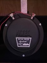
When a local picture theater was upgrading and as i knew the owner I got hold of a working pair of Altec voice of the theatre A7 horns and the matching 811b flared horns, these were set up in a small venue we had permanently at the time with the W-Bins above to fill in the bottom end. The A7's are long gone but i still have the 811b's in storage.
That was the early years and it tuned my ears to like high efficiency pro speakers and horn loaded compression drivers as the years rolled on.

This drove the LCR build in 2011 that uses Pro sound drivers with 100db(+)/1w for the LCR. When i added some basic surrounds they were poorly matched efficiency wise Audyssey in multiple pioneer apps has always set the LCR at -12 and everything else at +2 or there abouts 🙂.

So to today.......
These days the main use for the sound system is HT, it's rare that music is played. So the purchase of a new 85" tv a few months back opened up the pandora's box of dolby vision and dolby atmos which drove the upgrade of the 6yr old amp to a new Pioneer LX505 Elite so we could consider using/building some atmos speakers.
This then led into the rabbit warren and what components to use.
Taking the dot points from Step one of the design and build.
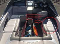
  • SAF - important, very, she puts up with a lot and surrounds/ceilings intrude very much into her space.
  • Space constraints - the SAF drove the need to minimise space used, bass extension was the main compromise ut consider i cross all speakers at 80hz at the amp this wasn't a huge deal.
  • How loud - now this was a biggy to match up to the front LCR and be capable past reference levels. We go close to reference levels watching movies.
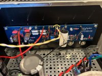
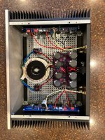
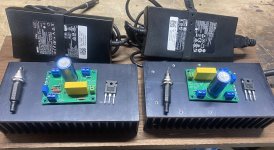
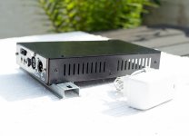
  • Amps - well nothings cheap in AU and i hate fan noise so the existing Pioneer amp does all the floor level channels, the atmos ceilings will be handled by 300w class D amps. The Tapped Horn and bass bins are already driven with 600w Class D.
  • What sort of box - Bass reflex, didn't need to think hard on this, mind you the Atmos speakers will sealed just to further reduce size.
  • build my own cabinets
  • budget - i'm a cheap man for this stuff and currently not working so budget was a factor. Some of you may argue this as/if you read more 🙂

So re-installed WinISD and off to parts express PE to do some research and modeling, all initial searches limited to 94db or better efficiency and aim of 2-way and speaker size around 10 to 12 litres maybe a bit more depending on the tweeter.
Believe it or not I did find suitable drivers that modeled well in WinISD, added them to cart along with some bits such as banana sockets.......... went to checkout....

Then some reality set in with freight cost, on an US$800 order freight was north of US$600 !!!!!! That was the cheapest option and no real change from AU $1900 to land it at my door in Australia.
Ouch, not happening, I envy the free freight options for the US members

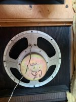
So back to the Rabbit burrow and WinISD ...... for info, there is no real options for PE range here in AU. A week of research finally lead me into car audio options but finding anything with even vague TS parameters was hard, not buying something i can't model..... till i stumbled on these 
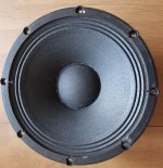
https://hertz-audio.com/product/car-audio-coaxials-mille-pro-mpx165-3/ with a full set of TS parameters.
Just a little low on the desired efficiency but it was a small compromise in the end. Now 8 drivers ended up costing AU $1200 so still not in the budget range 🙂
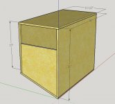
So decision made more time with WinISD to nail down port sizing. Ended up with a 60mm port close to 300mm long with the aim for a box tune of 60hz. I have always tuned below the sub cross over point, personal preference.
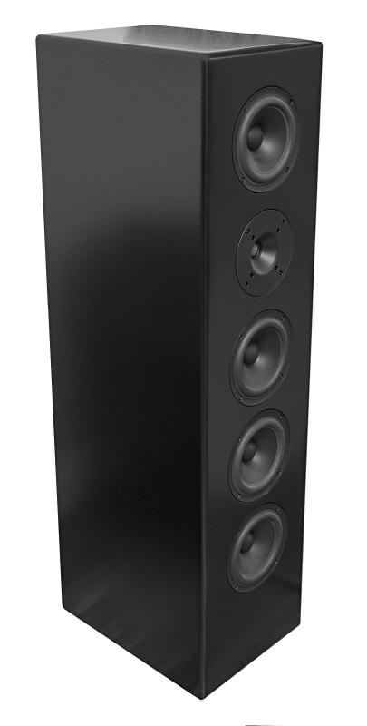
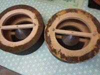
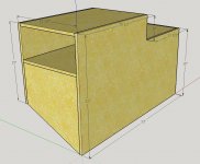
Now that port in a box 200mm wide 160mm deep and 330mm tall resulted in more compromises not to mention the desire to have angled sides.... In the end we got a 64Hz box tune, not bad considering sizing and volume used by the port (see photo's below)

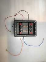
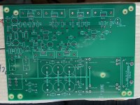
Onto build it.... Sorry nothing prior to glueing ports in, I had build one box and played with the port using DATSv3 to check variants.

OM5-100_M536716_02.jpg

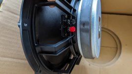
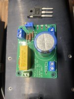
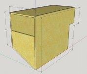
port is 65mm OD 60mm ID PVC with a 90 elbow hard against the rear wall bore going up to behind the speaker, the speaker mount cutout got sealed with the excess resin i had mixed up.

OM5-100_M536714_02.jpg

The banana plug mount is 3D printed and is at the top of the bax as it was the only place left, it is also for resin glued in place for an airtight seal.

Yes that is what we call MDF but is technically High Density MDF, crappy from a dust perspective but i do run some good dust collection as woodwork is a hobby.
The sides are 10 degree angled and round over i think was a 1/2 inch.

P9151806.jpg


Undercoated but haven't yet drilled the holes for the magnets for the front grills, yeah i know a bit backwards.
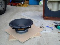
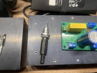
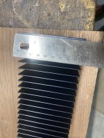
On the right is the Harvey 10" cabinet saw with a digital measured fenced to 0.1mm, going back to repeat a cut is not a problem.
As you can see the port tubing ate into the internal space and the angled cut on the entry was needed to clear the banana socket. Can't prove it but it seems the angled entry helps with the closeness to the internal walls. a slightly better view.
P9151812.jpg


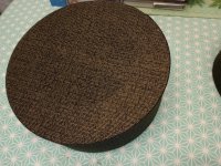
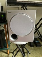
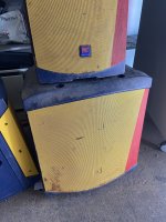
Finished surrounds at least....
I have measured them with DATS and REW but have no graphs to post, sorry
OM5-100_M556864.jpg


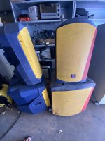
The sides are on stands at the ends of the 4 seat MLP that we sit in the middle of. The rears for the 7.x are a compromise on height due to the near full width glass doors 4.5M behind the MLP but they are angled down and in at the MLP, Mounts are standard VESA wall mounts using 5mm threaded inserts in the speakers
OM5-100_M556859.jpg

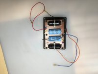
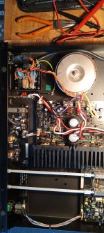
Here is the rear of the speaker
OM5-100_M556862.jpg

I may 3D print some cable management. the right angle plugs have a 3D printed spacer holder to stop them shorting.

The grills use a 3D printed from with magnetic attachment, they are 220x200mm. Grill cloth is held in with fly screen

OM5-100_M556869.jpg


This makes them easy to put on and remove.

OM5-100_M556871.jpg


So foot notes.
These were fully designed in Fusion 360 including drill templates for all screw and magnet holes. Clamped and glued only. have used a few brads in the overheads in progress to stop glue movement.
Besides small bits we ended up buying two small cordless palm sanders just to not change paper. a HVLP spray gun as all the others are buried in storage. On top of that the existing compressor developed a leak so a new 15cfm 150l Tank silent compressor made it's way into the garage 🙂 Hey any excuse for new tools.

Questions and comments welcome
  • Like
  • Thank You
Reactions: Wright and GM

Please check me on this Xover refresh

Hi all. I am in learning mode so I want to make sure that I am on the right track with this crossover refresh.
The picture below is of the back the front and then a mirror of the back for a clear view of where everything is.

Am I correct in thinking the the only Electrolytic in the signal path is the 22uf ? The others appear to be parallel. Would I be correct in thinking that I would do well to use high quality NP Electrolytics for the 47uf's and the 100uf and the replace the 22 (T), the 6.8(M) and the 4.7 (T) with something like ClarityCaps or the like? The two plastic film caps are just outside 10% on one speaker so I thought I might as well replace them. Thanks for your guidance and teaching on this.

1696457814777.png

For Sale Assembled LM1875 amplifier boards + Extra PCBs + extra ICs

Hello everyone,
up for sale stereo LM1875 amplifier boards + extra PCBs + LM1875 ICs. This is sound quality wise well regarded probably because of second harmonics. (Third party measurement link HERE)

  • Location India.
  • Tested and working
  • Genuine LM1875 ICs bought from DiyAudio member.
  • Boards are red gold plated from chipamp.com
  • Genuine Keltron, Wima, Nichicon capacitors brought from Project Point and The Audio Crafts (India)
  • There is extra 2 channel PCB + PS PCB + 2 LM1875 ICs. Which you can diy yourself.
  • More pictures available. Any query please message me.

The sale includes following :
1) Two fully assembled LM1875 boards.
2) One fully assembled power supply board.
3) Two pcb bare board for 2 channel lm1875 amplifier
4) One power supply bare board for lm1875 amplifier
5) Two genuine LM1875 ICs.
kindly see attached pictures.

Selling for Rs. 3500/- (42 $) Shipping extra.

Note :
  • No return, exchange. But would gladly help for any query or guidance or troubleshooting if any required in my capacity.
  • DIY envolves working with high voltages.
  • Build guide available online.

Thanks and regards
Hiten
Photo1.jpg

--
Photo5.jpg

--
Photo3.jpg

--
Photo2.jpg


The sign and date are for Indian Audio forum which is a requirement there to post. So didn't bother to take extra pictures.

Regards.

QUAD CDP-2 problem

I have one of these really quite wonderful little machines. However it is suffering from this problem…
When the machine is switched on at the rear, then taken out of standby, drawer opened, CD loaded, drawer closed - it will read the CD index and all functions can be accessed successfully.
However, if the drawer is then opened and closed again the player displays OPEN when the drawer is closed and will not read the CD. If the player is then turned off at the rear and turned on again, it will function perfectly.
I have stripped the drive down, cleaned away old silicone lubricant, used tiny amounts of SPG on moving cogs and racks, replaced the door opening belt, contact cleaned the micro switch, and cleaned both sides of the laser lens. I have not, and see every reason not to, moved the potentiometer setting on the laser. Electronics have been left alone.
I’m guessing that on player power up, the laser head is positioned correctly to read the CD index, but fails to do so once the drawer open and close sequence happens, perhaps because the player doesn’t think the drawer is closed…

Measuring DSP implemented (JRiver) crossover

Greetings all,

I have implemented a simple two-way (for learning purposes) crossover in DSP of JRiver. It clearly works as verified by turning it on and off and listening to the different drivers, but I cannot find in JRiver documentation how to input the measurement signal from REW to JRIver, so I can measure the speaker. Both JRiver and REW are installed on the same computer.

Any help or reference to JRiver documentation would be appreciated.

Kindest regards,

M

New member from Worcestershire

Hi, I'm joining because a lot of the posts look interesting and there are threads ones I could contribute to, now I am retired and have a bit of spare time.

I have been fiddling about with hifi for over 45 years, starting with a Sinclair Project 5000 amp that was pre-assembled but needed a degree of adjustment to keep the 5 pin DIN input plugs working, not to mention the plastic slider potentiometers. As I am a mechanical engineer, I have some appreciation of analogue electronic components as in my youth they were used in control systems and instrumentation – for example, I could calculate the LaPlace time domain transfer function of a simple circuit which really helped understand loudspeaker crossovers and what capacitors and inductors did to frequency response.

After the Sinclair, the next diy item was a Crimson Electrik kit amp, two CE1704 power amps driven by a CPS 6 power supply with a hefty toroidal transformer. This was complemented by a CE CPR 1 pre-amplifier kit. Over time the pre-amp was replaced by a NAD3070 with remote control, until that had protection circuit issues which were beyond my abilities. I now have an Audiolab 6000 pre/power amp, still with the Crimson Elecktrik CE1704 providing power for the bass inputs of a pair of Mission 773 speakers. The Audio lab 6000A not only provides power, but also the DAC for a NAD C541i CD player, now only a transport as the internal DAC shows its age in comparison to the Audiolab.


I have also inherited and refurbished various bits of kit such as a pair of 1990’s TDL Near Field Monitors – new Peerless bass/mid drivers and tweeters (the original rectangular faceplate ones are no longer available) and revised crossovers because the new drive units are 6- and 4-ohm nominal impedance, not the original 8 ohm.

At the moment I’m wrestling with a Cambridge A1-1 Integrated amp, I use it for audio with my computer. This is the original Mike Creek design with “Copyright MRC 1995” on the circuit boards. the main switch board fuse has gone and the power light won’t come on. Looks like the transformer secondaries have short circuited to earth, but I’ve put up a separate post to see if anyone has experience of this amp including what the secondary voltages should be.
  • Like
Reactions: chrisng

For Sale Dayton RS1202A Subwoofer

Hello! This is a discontinued subwoofer. I believe it sold for $1200 when it was sold. This unit is new in box. It's dual 12's in a sealed cabinet. The components used are still sold on PE:

Dayton RSS315FHA-8 (2)
Dayton SPA-1000

On Parts Express that would run you $1000 just for those 3 components, so I am thinking $650 for the sub (local)

I'm in Dayton Ohio.

https://www.parts-express.com/Dayto...al-12-Subwoofer-System-***-300-767?quantity=1

Attachments

  • 300-767_HR_0.default.jpg
    300-767_HR_0.default.jpg
    43.6 KB · Views: 104
  • 20230927_182818.jpg
    20230927_182818.jpg
    362.5 KB · Views: 110
  • 20230927_182715.jpg
    20230927_182715.jpg
    442.6 KB · Views: 112
  • Like
Reactions: mordikai

High SPL bass section for Wakeboard boat

Hi I have been lurking here for months doing hours of homework and now it is time to ask for some help from the experts. I have attempted to teach myself Sketchup and Hornresp and have read any related thread I could find. Here is what I am trying to do:

Goal:
A high SPL base section for a wakeboard boat. SPL is the goal but I don’t want something that sounds terrible. No one-note-wonders.

Mids and highs are extremely loud on the boat. It has been impossible in the past for the base section to keep up. More SPL is better

Amplification:
1000W RMS via Alpine PDX 1.000 Class D mono 12V amp. This amp will put 1000W RMS into either a 4ohm or 2ohm load (same watts for both). Includes a built-in LP filter adjustable from 50Hz – 200Hz and a built-in HP filter selectable at 15Hz or 30Hz

Frequency Response
My homework has suggested that it is futile to try to go too low, but I am not sure how low is too low. I want the base to be strong and impressive. The mids and highs are extremely loud am guessing that the most energy I can put into the 50-200Hz band the better. Advice here is appreciated.

Is this considered a sub? I don’t really care what we call it. I want an impressive base section that can keep up with the rest of the system.

Music
On the boat the music selection is often dominated by top 40, country, Hip-hop, rap and some dub-step(ish) music.

Driver Selection
Open season! I will be purchasing new drivers for this project so I am open to suggestions here. My initial thought is to use as many of the biggest pro-audio subs with as much efficiency as possible. I want to keep the total impedance of the box at either 4 ohms or 2 ohms to get the most out of my amp. My budget is pretty flexible. I don’t want to throw money away but I am willing to pay for quality.

Space
Here is the catch and the part I need the most help with. I have very limited space. I have attached some sketchup drawings of the space I have available. There are 3 shapes that I will be able to fit into the boat with minimal modifications of the boat. I would like to start here. If I can’t achieve my goals I could go with bigger options but I would have to get out a saw and start hacking fiberglass pieces apart so I would really prefer not to. The options below are about 90 – 110 liters internal volume (3.2 – 3.9 ft3).

Alignment
Sealed and base reflex are out. I need the driver(s) to be housed inside the box with only a port firing into the boat cabin. So any alignment that achieves this is fair game. I have been playing with 4th order and 6th order bandpass as well as tapped horns. The box will live underneath a fiberglass bench seat that is vented into the cabin with a port that can’t exceed the maximum size of 10 inches high by 12.5 inches wide. Hopefully smaller.

Request
Can someone help me squeeze the most base possible out of the boxes I have shown below given the above requirements?

Attachments

  • X-15 inside3.jpg
    X-15 inside3.jpg
    205.4 KB · Views: 493
  • STBD short box.JPG
    STBD short box.JPG
    55.9 KB · Views: 465
  • STBB long with stepdown.JPG
    STBB long with stepdown.JPG
    93.5 KB · Views: 456
  • STBB long with stepup.JPG
    STBB long with stepup.JPG
    98.5 KB · Views: 459

W6-2144 - Design time!!

Just bought a pair of these on sale:
Tang Band W6-2144 6-1/2" Paper Cone Full Range Driver 8 Ohm

They look amazing, weight 8lbs 3oz ! The last FR speaker I built (or my dad built?) I was probably 14, and it was just a closed box with spare speakers.

I'd like to build a TL or MLTL, maybe TWQT ?

I've built / designed ported boxes mainly, using win-ISD. Never used Hornresp or designed any horns / TLs. I actually monitor in the studio with some TL studio monitors, so I do like the clean deep bass I get, though it's not earth shaking.

These will be used for music mainly, but maybe the odd movie (especially for the kids). In the basement den. Not a huge room, so these will probably be kind of near a wall. I have some ceiling treatment in the room from when I used it for recording. I'll probably use my old Yamaha receiver for now, and maybe get a little class D in the future.

At this point, I'm looking for help, tips, design ideas, etc.

Main goals:
-Natural, extended low end
-great imaging
-music mainly, but i know I could always add a couple capacitors (HPF 80hz) and a sub if I wanted to turn it loud on movies.
-Narrow tower with these at listening height.

I listen to everything from techno to Bach. Or maybe it's just techno AND Bach? Just help me make sure the 808's and pianos will all play nicely 😀

It seems like there are SO many designs out there for FR TL's, etc. Any recommendations for this driver? MLTL? TWQT? etc? Offset the driver?

Do I need some kind of baffle step circuit, since I prefer this to be a narrow (but maybe deep) cab?

thanks in advance...

Wavecor WF152/182 BD/CU for midrange, any experience?

From time to time I get back to looking at these drivers, I still recall bass and its quality of WF182BD09, measurements were also good, and I basically see no issue using WF drivers for midrange duty. Their datasheets are great, contain distortion measurements, and suggest that midrange band 300-2000Hz is well behaved, and symptoms of cone edge resonances are well mitigated.

WF182BD03 was measured by Hificompass, and based on that I would not hesitate to use this driver for midrange.

Do you have any experience, either measurements or listening?

Unity gain non-inverting buffer options?

I have an analog circuit that includes three amplifiers. Two of these will be op-amps. The third one is just a unit gain buffer, non-inverting. I could design the circuit using another op-amplifier, but then there are three and there is no IC package wtih three. I could use a four-amp package and not use one amplifier. But that seems like a waste. So is there a single amplifier unity gain stable buffer for audio applications, or should I use something else altogether (FET buffer, etc.)? This is for DIY, so likely thru-hole components but SMD is not out of the question for active devices.

What are some options for the unity gain buffer?

Cross-over for -- VIFA XT25BG60-04 and SB Acoustics SB15MFC30-8

Any one have a cross-over for this?

I actually had an SB26 fabric dome tweeter I could have used with is cross-over:
https://www.diyaudio.com/community/threads/2-way-sb15mfc-08-sb26stc-04.315253/page-2
Is the cross-over in the link a good starting point?

Or Zaph has a good x-over for the Scan Speak 15W8530K00 and the Vifa XT25TG30-04:
http://zaphaudio.com/ZD5.html
Is it a better starting point?

Attachments

  • 20230920_173628.jpg
    20230920_173628.jpg
    545.3 KB · Views: 458

For Sale Tortuga LDR Attenuator ePot.V3 Max plus OLED display

SOLD.
This is a new, unused V3 Max, Rev C LDR attenuator board – current production. It also comes with the OLED display module and a spare LDR Attenuator module (one of the LDRs has a solder iron burn mark). The OLED display and spare LDR module were briefly used in another preamp, but the ePot.V3 Max board is brand new from Tortuga.
You'll need a power supply, I/O connectors, a case, etc. to build this into a preamp. Complete documentation on the Tortuga website. I can’t control what you do with these, so sold as-is. These parts would cost $500 new, for sale for $200 plus shipping.
Mike
IMG_7480.jpeg
IMG_7482.jpeg
IMG_7483.jpeg
IMG_7484.jpeg
IMG_7487.jpeg

Faulty electronic selector switch?

I have purchased a "faulty" Kenwood A-47 amp from E-Bay. The amp is now functional, I have put larger heatsinks on the dreaded main amp driver chips. My only problem now is that the electronic selector switch doesn't work. I input a signal to the Aux input, move the selector switch (the indicator lights change) but the input continues across all the inputs selected by the switch. Anyone any ideas?
Stuart Preston.

Kirksaeter Monitor 120

Hi everyone.

Last time I bought quite decent vintage speakers produced in 1979. They are Kirksaeter Monitor 120. Incredibly good condition looking on their age. Nearly no marks of wear on boxes, all working. Really good, balanced sound and not bad bass taking into consideration boxes are small - as usual for monitors. People from AudioKarma say they are remarkably good speakers. But... they are old, that means recapping is a must, recabling also. And the problem begins - I have searched through internet for any info about technical matters and found nothing but technical data. Maybe some of members took such Kirksaeters on workshop and recapped them? Any other forum has no info about that. Any advice highly appreciated. Here are pics of speakers and their crossover.

IMG20230708112211.jpgIMG20230708111706.jpg

Alpair 11ms, 10.3, Pluvia 11, or other?

Hi all.

I've recently assembled a pair of 7ms CGRs, and I'm quite happy with the result. I haven't had a chance to test them in a good room yet so can't give full evaluation for anyone curious. These are the only full range drivers I have heard, and I don't feel like I'm lacking anything over a two way in my current use case - apart from outright headroom.

I am curious to build a new standmount with either the 11ms, 10.3, or Pluvia 11. Possibly even the CHN110, but I understand that is designed for use in a bigger box.

I'd be happy to stick with the 7ms for my duties, however these will one day go into a WAW with some Alpair 12pw which are sitting in boxes, waiting for when I have space to have a large speaker.

The new speakers I make will most likely only be used nearfield. I am looking for something that can go a little lower than the 7ms, and also have more headroom - hence the size upgrade. I'd ideally be looking for extension into low 50s/high 40s - or low as possible realistically from a small box fullranger. In my room at the moment the 7ms are reaching low into the 50s.

From what I've read, I'm not sure if any of these drivers will reach lower in a small box, apart from possibly the 10.3. I'd appreciate some advice off of more knowledgable members.

I am most curious to hear the 11ms as that's the latest and greatest from MA, but I'm a bit concerned looking at the dip in the freq response, and then the peak in the treble. I'd be happy to just eq that down if it sounds okay but I'm worried it's distortion which can't really be fixed.

I'm curious to hear any thoughts from anyone who's heard the above drivers. Also, I know there's been some similar threads, but I wasn't able to see much information from them, I was wondering if there are any more opinions now.

Thanks

Intel Celeron N5105 processor @ 2GHz enough for audio?

I bought fanless mini PC (W11 Pro) with an Intel Celeron N5105 processor running at 2+GHz,
to use as a low noise source running JRiver to feed my 8-channel Topping DM7.
I just ran it a bit yesterday and I thought I heard a few minuscule hiccups or dropout.
Anybody has an insight into what sort of processor/speeds would be required (48kHz, 6 channel FLAC with JRiver convolver).

Jan

https://www.amazon.com/MeLE-Quieter2Q-Processor-Quad-Core-Computer/dp/B0BYZ91RFL/ref=sr_1_3

RSPlayer - Diy-friendly Music Player for Raspberry PI (or any other ARM64 Linux computer).

Hello fellow DIYers,

I would like to share this piece of software I created for my own needs and I hope it might be helpful for others too.

Here is the repo and documentation: https://github.com/ljufa/rsplayer

Any contribution, feedback, suggestion, or question is appreciated.

What to buy to make a diy bookshelf speaker

Guys… i have a esotar t330 dynauadio brand new tweeter. I also have a melo davis t330 copy of a t330 tweeter…

Bought them thinking my SF t330 original cant be fixd but in good graces a little rewind of the coil and all is good.

So i have a spare, thinking of making a bookshelf speaker.

What is the best mid and crossover or dividing network pair for the t330?

Cambridge A1 MK1 amplifier - main power fuse blows

I have a Cambridge A1 Mk 1, the one with the volume control at the far right, and a few days ago the power light went off as it was in use at low volume , and sound stopped completely.


I disconnected the amp from the mains, took the lid off and found that the fuse on the power supply switch board (top left in photo) was blown. A new fuse T2A 250 V blew out immediately the amp was switched on. I then disconnected the amp from the system and carried some continuity/resistance checks. I noted that the rectifier circuit is actually built into the main power amplifier board and I found that the secondary output power leads from the transformer to the rectifier bridge (purple and yellow in the photo) were both zero resistance to earth, even when I disconnected the two fuses. As I read the layout, those wires should not be earthing, as they are feeding power to the rectifier circuit which then feeds the two amplifier circuits.

The red and white wires from the secondary windings are earthed as they are connected to the black earthing wire at the “rail” which is between the two large smoothing capacitors , and the "rail" is achieved by a large trail of solder under the circuit board.

As I don’t have a schematic, I’m basing my knowledge on a circuit diagram of a Crimson Electrik CE170 kit from 1980 (no IC power transistors), and application of the basic arrangement to a few other amps including a NAD3070.

My conclusion is that the secondary windings of the transformer have short-circuited to earth. Can anyone confirm this?

Attachments

  • Cambridge A1 all.jpg
    Cambridge A1 all.jpg
    448.2 KB · Views: 138

Design criteria for X.5-way speakers

Attached is a picture of 4-way speakers; Acoustic Research AR9. Is it feasible to redesign these speakers to be 3.5-way? It might be achieved by redesigning the crossovers with the elimination of the high-pass filters of the cone midranges. As you can see, the AR9 has an 8” woofer as the mid-bass driver. Why did manufacturer not use that 8” driver to help woofers playing bass? If it’s because of preventing distortion, they also have 8” woofer models in the conventional 3-way bookshelf series. Or the X.5-way speakers MUST only have midrange drivers as large as woofers, is this a criterion?

Attachments

  • 0D7C9F7B-09F5-4323-8147-EF090AB80F8E.jpeg
    0D7C9F7B-09F5-4323-8147-EF090AB80F8E.jpeg
    6.6 KB · Views: 72

Raspberry Pi does not want to boot.

Since, my Raspberry PI 4 does not want to boot, I am asking here if any audio players exist which provide the same functionality like a Pi. I changed the SDCard unsuccessfully. The Raspberry Pi 4 did not boot notwithstanding I tried to boot several times. The LED flickers showing some sort of mysterious activity, but without booting. As this version of Pi has two HDMI ports, I tried to connect to both of them. Still, unsuccessful. It is becoming like a recurrent nightmare, since I love music, I am at a loss not having a substitute. If anything exists that is ready to use, I will consider it.

Chip amp RMS

I was watching a YouTube channel that I’ve begun to like and one video was about “umpth” watts. He did some math and talked about how meat and potato wattage output ratings tend to be much lower than in specs. I already kinda knew that but his numbers were quite a bit lower.

This morning while having tea and poking around Parts Express, I was reading q&a on this Wondom 100w mono board. One person said they were only able to measure ~25w rms. In another query a staff member explained that the 87w @ 1% thd wasn’t listed as rms and was only short bursts. He said ~40w was more realistic for an rms expectation. I totally should have known better and been more critical in my reading of specifications.

The question now is what kind of actual rms power might one expect from a class d board, assuming the power supply is adequate? Also, we’re talking about brands like wondom, sure, ice, Dayton, ect. I realize that a true 15w is actually pretty good and will get most speakers loud but I’m concerned about subwoofer power. In particular, I’m planning on two small ~.25cf sealed enclosures for two Dayton Epique 5.5’s.

Depending on enclosure volume winsld predicts around 150w to reach near xmax, which apparently the 5.5’s can do fairly well behaved. Eq cut here and there for room corrections and seems every bit of 200w might be needed from time to time. I’ve personally noticed that my Anarchy 554’s don’t seem to hit anywhere near xmax off what should be ~70 on low bass.

This Wondom 2x160 is on the Anarchy 5.5’s with 19a 24v mean well. Dayton KABD 2x50 is providing the dsp’d line out.

https://store.sure-electronics.com/product/660

I’d like to give this KABD 4x100 a go bridged for 2x200 but I’m now concerned that it won’t be giving an actual 200x2 rms.

https://www.parts-express.com/Dayton-Audio-KABD-4100-4-x-100W-Bluetooth-Amp-Board-with-DSP-325-434

If this whole much less rms power than advertised thing is correct then do I need some 600X1 boards to get closer to a real 200w? As I’ve been looking around I don’t see any rms ratings on boards…

How to coonect the filament voltage elevator

Hello Folks, my tube power amp transform have 3 separated 6.3vac o/p are 2A, 5A, 5A respectively, so I just use 2A with Lm317 regulated DC 6.3VDC for voltage elevation connection to B+, and other two 6.3VAC direct supply to power tubes. My question is the whole amp just need a single voltage elevation circuit or not ? Or should have all filaments supply do the same this connection ?
If I deploy 6.3VAC virtual ground by two 100R resistors to ground, then how to make upper connections?

Obsolete Mid-Bass Driver 12W360 (FOSTEX) - Test Review with Diagrams wanted (e. g. from Magazines "Voice Coil" or "Klang&Ton")

Only the short form data - go attachment in post #166 under
https://www.diyaudio.com/community/threads/best-woofer-50hz-300hz-hi-eff-maybe-15.158170/page-9
so as the websites unter
http://wanko.pecori.jp/cside/12w360/12w360.htm
https://web.archive.org/web/20060621032917/http://wanko.cside8.com/cside/12w360/12w360.htm
I have as information.
Maybe one of the members can upload a test review - thank you very much.
P.S.: Currently replacement for this FOSTEX vintage professional series are to find under
https://www.bell-store.de/c/lautspr...ile-speaker-units/woofers-us-magnetics-fostex
but without detailed datasheet - go to
https://www.bell-store.de/p/12w360-8-us-magnetics-woofer-replaces-fostex-12w360

Attachments

  • Fostex12W360+Supravox135LB R front.jpg
    Fostex12W360+Supravox135LB R front.jpg
    94.5 KB · Views: 86
  • DSC06076.jpg
    DSC06076.jpg
    348 KB · Views: 86
  • 56112a28495082f431f6d9079242.jpg
    56112a28495082f431f6d9079242.jpg
    206.6 KB · Views: 81
  • n99290308.3.jpg
    n99290308.3.jpg
    41.2 KB · Views: 85
  • P1014896.jpg
    P1014896.jpg
    43.5 KB · Views: 84
  • bf37e28d-e221-4860-b0b3-38aa390603f6.jpg
    bf37e28d-e221-4860-b0b3-38aa390603f6.jpg
    142.2 KB · Views: 87
  • ymqpmzc9fssvvuviuhc6.jpg
    ymqpmzc9fssvvuviuhc6.jpg
    216.7 KB · Views: 84
  • xgqrjj37iyl0mc5hoh0n.jpg
    xgqrjj37iyl0mc5hoh0n.jpg
    173.8 KB · Views: 87
  • 111.jpg
    111.jpg
    26 KB · Views: 98
Projects by fanatics, for fanatics
Get answers and advice for everyone wanting to learn the art of audio.
Join the Community
507,631
Members
7,881,011
Messages

Filter

Forum Statistics

Threads
405,903
Messages
7,881,011
Members
507,631
Latest member
Paolo Gennari