Hello everyone.
The PeeCeeBee Preamplifier is here! PCBs will be available via group buys arranged in this thread.
_________________________________
UPDATE October 8 2021: All boards from last batch gone. Entry open for 3rd group buy. Shipping has resumed to most countries.
_________________________________
BOM with parts placement indication uploaded
>Here<.
Setup Guide uploaded
>Here<
Drill Template uploaded
>Here<
_________________________________
Introduction:
It is a fully bipolar transistor based symmetrical "Class-A" push-pull preamplifier with real-time adjustable pure Single Ended harmonic distortion level - from less than 0.001% to over 1% - with second harmonic being predominant in all levels! It also includes its own low noise regulated power supply section on-board, that uses the same transistors used in the active section. It can be used as a very good headphone amplifier for voice coil impedance of 32ohm and above. By using a higher gain than the default +6dB, it can be made to put out 10VPP into 600ohm headphones or upto 25VPP to power-follower type amplifiers.
Description:
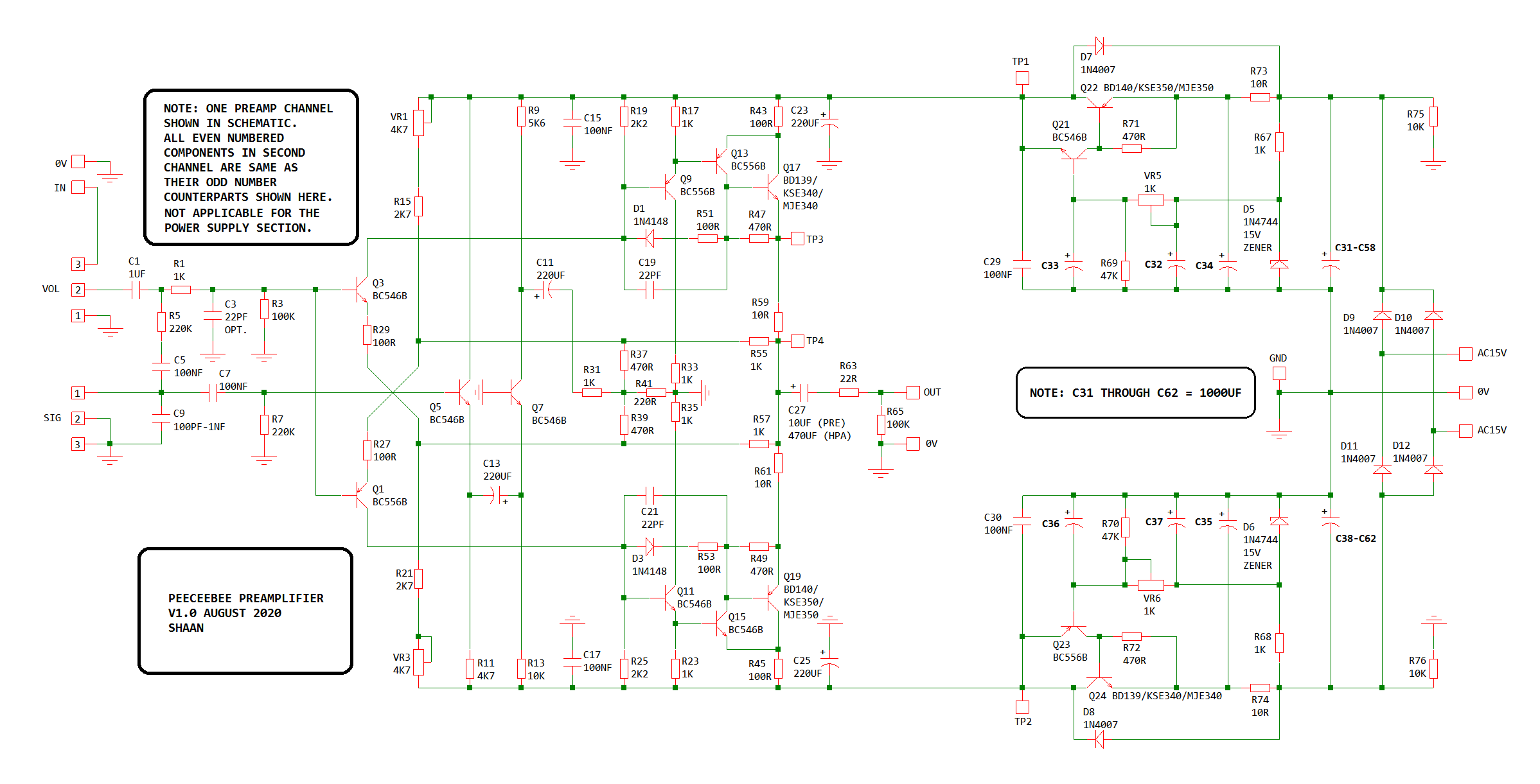
The preamplifier consists of two gain segments per channel, one push-pull (PP) and one single ended (SE), preamp output is taken from the PP segment. The PP segment uses low gain with very high global negative feedback and generates a clear replica of the input signal with minuscule THD. The SE segment uses high gain with zero global negative feedback and produces the same signal with massive amounts of low-order THD. The PP segment is directly fed the input signal from the volume control. The SE segment's output is coupled to the feedback node of the PP segment, and the SIG ("Signature") potentiometer controls the input signal to the SE segment. With SIG control set to lowest, the SE segment will contribute almost nothing in the main output due to its high output impedance compared to the feedback node of the PP segment. As we gradually increase the input to the SE segment, its output will present gradually more harmonic content to the feedback node of the PP segment where it will be compared with the feedback signal from the output of PP segment, and the difference between the two signals is presented to preamp's output. Since high amount of harmonic content at high frequencies is often unwelcome, the input to the SE segment can be lowpass filtered with user chosen maximum frequency of interest, so that the high frequency signals can be chosen to contain the least amount of harmonics, and treble definition remains intact.
How it sounds:
It sounds neutral, and it sounds warm, and everything in between! How much neutral or warm depends on how much you want to turn the SIG pot! In my system I have been listening to it from morning to midnight, day after day, with the SIG pot turned towards a low setting during daytime and to a slightly higher setting in the evening.
As expected, in its minimum SIG setting, the sound is extremely clean, with a large soundstage, and in its maximum setting, it is extremely sweet (masked), with a narrow soundstage. In my main system I found the sweet spot to be around 5-10% of the turn when playing music tracks where a lot is going on, and around 45-50% when I am listening to chants or other music types where the music is minimal, calm and relaxed. At near 20% I feel the sound is very balanced, with the right amount of depth and detail I like, along with a touch of that "SE" niceness.
I feel that at the highest and lowest settings the system will have a tendency to become "special case", i.e. in both these extremes it may choose to sound very good with some types of music and not so good with other types, subjectively speaking! You feel the sound is not coming good for the music? Turn it slowly and find a sweet spot. But it is Extremely important that you wait a few minutes after reaching the new setting! Read on to know why.
The design was finished in March! Although the pandemic and subsequent suspension of shipping services delayed everything, I kept listening to the veroboard prototype everyday. And something very interesting and important regarding the SIG control has become clear to me in the last couple months.
The position of the SIG control that suits your taste must be found by spending some time listening in a set position. The potentiometer can be turned without any problem during music playback. But instantly finding out a sweet-spot this way is almost impossible - at that new setting it will sound pretty much the same as the last setting and make you feel like the control is not working, although distortion may have changed by an order of magnitude or more!
This is because our aural perception needs time to notice changes in the level of harmonic content, and significantly more time to make a memory out of it. So it is suggested that the user sets the SIG level to a position and then gives it some time of listening, then changes the setting to another level and repeat the listening. Expect at least a day of listening to find all the sweet spots for your system. I say sweet spot's' because if you listen to multiple types of music, you will almost certainly find one sweet spot for each type. Each listener will have his/her own sweet spots and the speed of finding them will vary, as some listeners have a more acute perception than others. That said, as I mentioned previously, around 20% setting the preamp can sound good for almost all types of music. Links to a collection of the harmonic levels at different output voltage into different load impedances are shared below in the "THD Spectrums" section. Note that there is about 1dB of output signal attenuation when the SIG potentiometer is at its maximum, this doesn't cause any problem during listening.
Side Note: I noticed that the phase of the second harmonic relative to the input signal was easy to manipulate by choosing the polarity of Q7/Q8 transistors (output of SE segment). Since March I have been using an NPN here which was adding negative phase second harmonic to the output. Recently I changed it to PNP and got the positive phase second harmonic. At first it sounded quite different, and felt like the overall definition has increased. It got me excited and I posted a page worth of it
>here<, thinking this is the way to move forward with the preamp. But after a couple days of listening it became apparent that the sonic appeal of the system has been lost with the positive phase second harmonic! I could not keep playing it for more than 15 minutes in a go! There is no high-order harmonics present beyond the 4th, but the sound started to feel thin and kind of bitter. Off to the workbench and reverted back to NPN, and the lushness of the output came back! Hence, back to old way (the better sounding way). The NPN actually outputs normal phase second harmonic, but as the SE segment's output is coupled to the feedback node (which is the inverting input of the PP segment), the harmonics get inverted at the output.
_____________________________________
All active devices are commonly available discrete bipolars. The PCB is a bit large, I decided to make it a little more spacious (I received many complaints about how congested my amplifier PCBs are. They're still congested!
🙂 ).
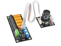
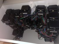
The onboard power supply is comprised of simple dual rail CRC filters followed by regulated capacitance multipliers in Sziklai follower config, powered from a 15V-0-15V/30VA center tapped transformer. There are two pots in the power supply section (VR5,VR6). Using these two pots the rails can be closely matched between +/-12V to +/-14.5V, and each rail can be trimmed individually. Instead of two large reservoir capacitors it uses 32 smaller capacitors, having much better filtering performance and keeping the profile low. Even with 40mA bias per channel I can hear absolutely no hum from the speakers or headphones. The preamp has no audible residual wideband noise, there is virtually zero hiss with headphones or speakers over ear.
Drill template and setup guide are being prepared and will be shared in a few days.
______________________________________
Input Impedance: 67Kohm
Output Impedance: 32ohm
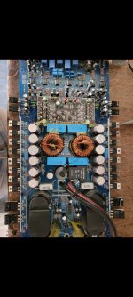
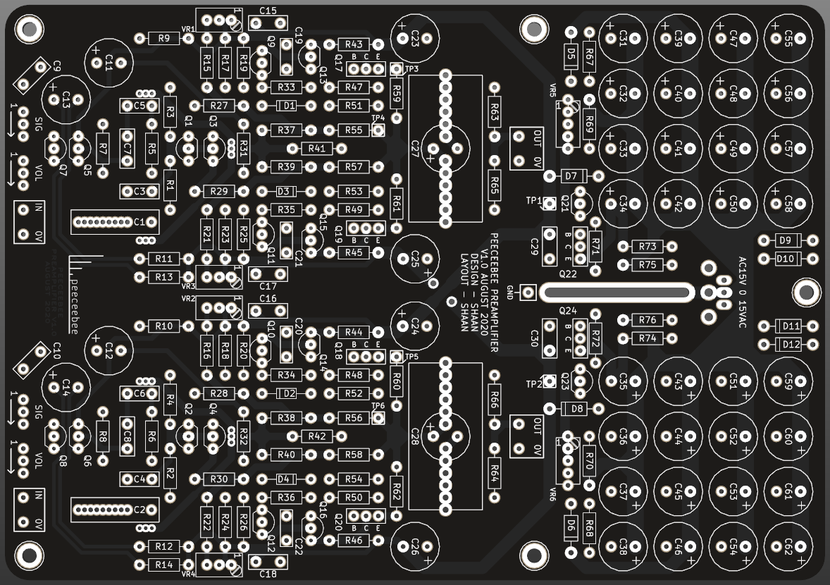
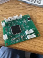
Layout snapshot:
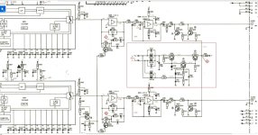
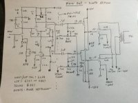
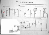
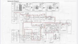
Schematic:
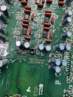
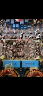
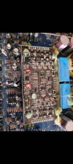
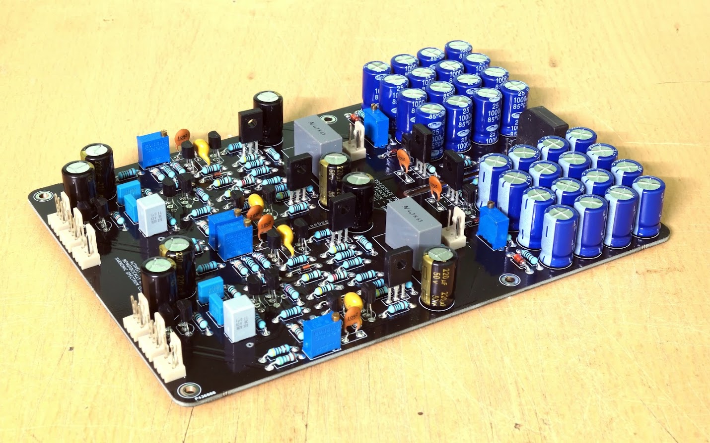
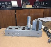
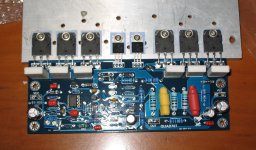
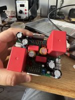
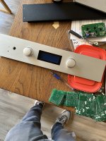
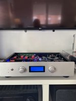
The prototype:
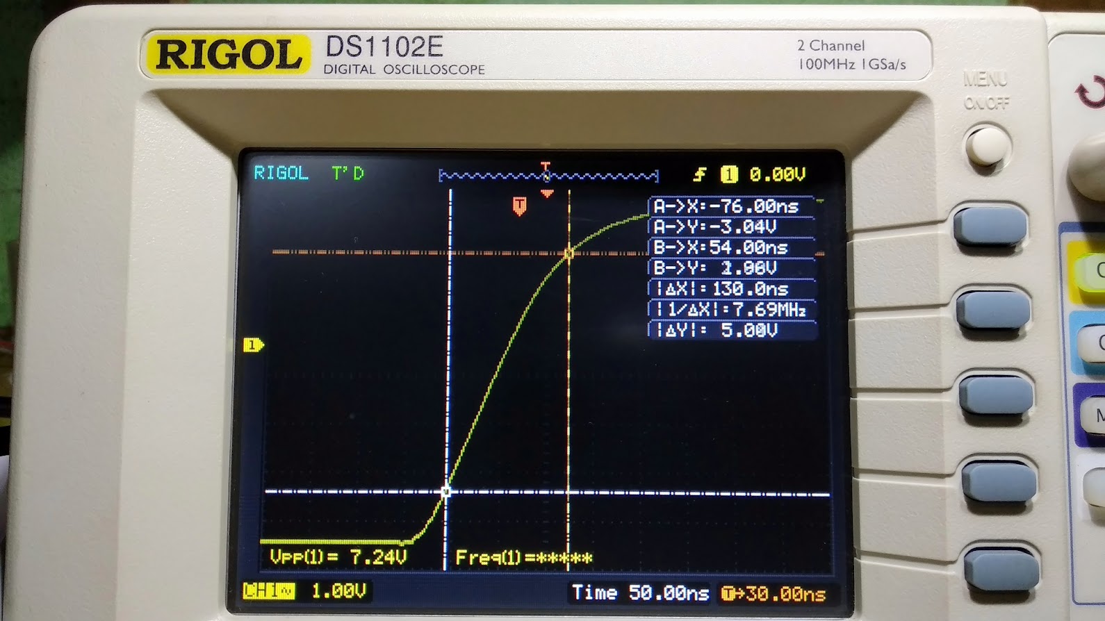
Input-Output delay:
Slew rate:
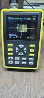
Harmonic waveform (at 1% THD):
Video Snapshots:
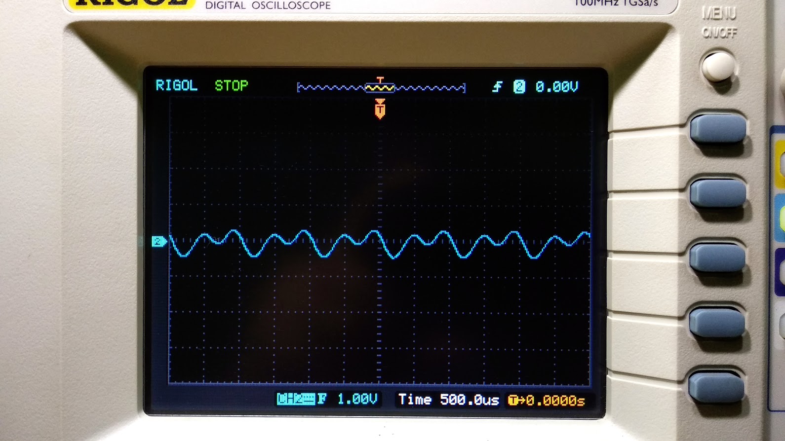
Power Supply Rail Behavior ->
Power Supply Rail Behavior
Power On/Off Transient Output ->
Power On/Off Transient Output
Clipping Waveform ->
Clipping Waveform
THD Spectrums (Peak-to-Peak output, Gain +6dB, 1KHz):
10Kohm load:
500mV -
Low SIG,
High SIG
1V -
Low SIG,
High SIG
2V -
Low SIG,
High SIG
4V -
Low SIG,
High SIG
8V -
Low SIG,
High SIG
680ohm load:
1V -
Low SIG,
High SIG
2V -
Low SIG,
High SIG
4V -
Low SIG,
High SIG
8V -
Low SIG,
High SIG
100ohm load:
500mV -
Low SIG,
High SIG
1V -
Low SIG,
High SIG
2V -
Low SIG,
High SIG
4V -
Low SIG,
High SIG
-------------------------------------
All the above shared documents and pictures can be availed in a single zip file
>Here<.
-------------------------------------
-------------------------------------
The PCBs are 1.6mm FR4 material with 60micron copper, black solder mask, white silkscreen and HASL finish. Dimensions: 170.18mm x 119.38mm.
-------------------------------------
Important information regarding group buy:
>> The PCBs cost USD20 for one unit.
>> International payments are accepted through PayPal only and payments from within India are accepted through bank account transfer/deposit, NEFT, IMPS and UPI.
>> Delay between placing the batch order to PCB plant and delivery of the boards to me will be 20-25 days.
>> Shipping is done for 3-4 packets a day to avoid stagnation at the clearing hubs due to the slow movement of international shipments.
Thanks.
shaan