As some of you are aware, I’ve been toying with the idea of building some “stupid power” tube amps for a while. The first tube amp that I didn’t “just throw together, then take apart” happened to be 200 watts and sounds fantastic. Naturally you want to keep going….
Doing it “properly“ by buying $10,000 worth of KT88’s and as much or more on custom iron is completely out of the question. I’ve been collecting TV sweep tubes, and transformer solutions that “should“ work - that is, nothing is run beyond its normal operating range. People (including me) have successfully used power toroids for output transformers. The catch is you’re really limited to 170 volts peak on a 120V winding, and stacking two is as far as you’d dare push it. But Antek makes some that are DESIGNED to put out 1900 volts. THAT got the wheels turning.
Im not planning on re-inventing the wheel in terms of circuit topology. Nothing too fancy, just a Mullard with k-followers directly driving the individual power tubes. This keeps g1 circuit resistance low and allows individual fixed bias. A bias servo will be used to balance individual pairs. This will need to be rung out first, as will overcurrent and excessive g2 voltage shutdown. I know the bias concept works, I’ve used it to balance transistor pairs. I’ll just need to ring out the gain structure and compensation for stability. With actual tubes. I have a batch of 21EX6 earmarked for this development. I figure I’d try to keep it all tube - including little pentodes as current sources for LTPs. If that gives me too much trouble there are always MJE340’s. Like other ‘pro’ amps, the power section would have limited gain, and a front end with 0-20 dB drives it. The whole front end and supervisor would have its own power supply, and the main B+, screen supply, and power tube heaters powered separately with a delayed turn on and shutdown under fault conditions. All this would be common to the various configurations I’ll be looking at over the next ~2-3 years.
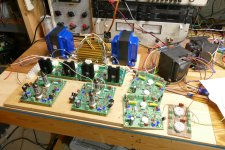
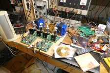
Will it ever get built? Who knows. But I have bought the dummy loads for testing and tuning the power supplies, and dug all the transformers out. It always starts there.
Doing it “properly“ by buying $10,000 worth of KT88’s and as much or more on custom iron is completely out of the question. I’ve been collecting TV sweep tubes, and transformer solutions that “should“ work - that is, nothing is run beyond its normal operating range. People (including me) have successfully used power toroids for output transformers. The catch is you’re really limited to 170 volts peak on a 120V winding, and stacking two is as far as you’d dare push it. But Antek makes some that are DESIGNED to put out 1900 volts. THAT got the wheels turning.
Im not planning on re-inventing the wheel in terms of circuit topology. Nothing too fancy, just a Mullard with k-followers directly driving the individual power tubes. This keeps g1 circuit resistance low and allows individual fixed bias. A bias servo will be used to balance individual pairs. This will need to be rung out first, as will overcurrent and excessive g2 voltage shutdown. I know the bias concept works, I’ve used it to balance transistor pairs. I’ll just need to ring out the gain structure and compensation for stability. With actual tubes. I have a batch of 21EX6 earmarked for this development. I figure I’d try to keep it all tube - including little pentodes as current sources for LTPs. If that gives me too much trouble there are always MJE340’s. Like other ‘pro’ amps, the power section would have limited gain, and a front end with 0-20 dB drives it. The whole front end and supervisor would have its own power supply, and the main B+, screen supply, and power tube heaters powered separately with a delayed turn on and shutdown under fault conditions. All this would be common to the various configurations I’ll be looking at over the next ~2-3 years.
Will it ever get built? Who knows. But I have bought the dummy loads for testing and tuning the power supplies, and dug all the transformers out. It always starts there.
Attachments


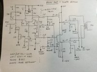
I figure I’d tackle the “350 watt” version first, prototyping with expendable 21EX6’s that I only paid $4 a pop for. Using the next size output transformer down, and for power an industrial control trafo I got from Skycraft (actually two identical). Move to a better tube once it’s proven out. With 8 ohms on the ”secondary” it works out to 1400 a-a. 600 volts at load will give north of 350 W. Screen would be derived from an existing 110V tertiary winding, and set to track the B+, dropping as the main supply sags to prevent excessive g2 current when clipping at full power.
Another idea is to use two interleaved power toroids, and keep the applied voltage down in the 340 V peak range. I happen to have a batch of old Plitrons that give just shy of 40V. Perfect. 400 watts RMS at 4 ohms. This arrangement yields 600-ish ohms a-a, running the outputs “low and hot”. A higher current tube is advisable here, and the supply should be about 400V at load. I have some stuff lying around that will support this. This idea may or may not get much attention, but it is possible.
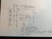
Ultimately where I want to go is drive the Antek 15T950 with 5 or 6 pairs of 26LW6. It will need one in the power supply, which will need to be at least 700V at load to make 800 watts. I’d take 1000 if I can get it, but I won’t get greedy. Unloaded it may need to be as much as 900V. I’ll have to build it and test, but I have the dummy loads now. How to get the extra voltage? Stack 200V worth of supply underneath it. That gives me a screen tap so I’m not dropping 700V in a power transistor, which is a recipe for smoke and flames. I was going to buy an Antek 800 VA 75-0-75 and add the 26 V heater winding, but lo and behold I found 3 old 600 VA cores with the primaries intact. A little rewinding and no expense necessary. And I can dial in the voltage I need.
Another idea is to use two interleaved power toroids, and keep the applied voltage down in the 340 V peak range. I happen to have a batch of old Plitrons that give just shy of 40V. Perfect. 400 watts RMS at 4 ohms. This arrangement yields 600-ish ohms a-a, running the outputs “low and hot”. A higher current tube is advisable here, and the supply should be about 400V at load. I have some stuff lying around that will support this. This idea may or may not get much attention, but it is possible.
Ultimately where I want to go is drive the Antek 15T950 with 5 or 6 pairs of 26LW6. It will need one in the power supply, which will need to be at least 700V at load to make 800 watts. I’d take 1000 if I can get it, but I won’t get greedy. Unloaded it may need to be as much as 900V. I’ll have to build it and test, but I have the dummy loads now. How to get the extra voltage? Stack 200V worth of supply underneath it. That gives me a screen tap so I’m not dropping 700V in a power transistor, which is a recipe for smoke and flames. I was going to buy an Antek 800 VA 75-0-75 and add the 26 V heater winding, but lo and behold I found 3 old 600 VA cores with the primaries intact. A little rewinding and no expense necessary. And I can dial in the voltage I need.
Attachments

I love the idea!
I would never dare to turn on such an amp at home (in my house that is), perhaps in a small adjoining, fireproof lean-to. 🤣
I would never dare to turn on such an amp at home (in my house that is), perhaps in a small adjoining, fireproof lean-to. 🤣
Hey....Have done this.....not they way that you have which is very interesting,...cost effective.....output tx was 900 gbp...do not underestimate the power of the 6/26/36 LW6...Tubes.....I got 1.5 kilowatts from 12 in ab1 pp 850 volts ht loaded quiescent....175 on the screens......beware of reverse screen current with them, Better tube is PL519.....Mullard....Does not exhibit this behaviorI figure I’d tackle the “350 watt” version first, prototyping with expendable 21EX6’s that I only paid $4 a pop for. Using the next size output transformer down, and for power an industrial control trafo I got from Skycraft (actually two identical). Move to a better tube once it’s proven out. With 8 ohms on the ”secondary” it works out to 1400 a-a. 600 volts at load will give north of 350 W. Screen would be derived from an existing 110V tertiary winding, and set to track the B+, dropping as the main supply sags to prevent excessive g2 current when clipping at full power.
Another idea is to use two interleaved power toroids, and keep the applied voltage down in the 340 V peak range. I happen to have a batch of old Plitrons that give just shy of 40V. Perfect. 400 watts RMS at 4 ohms. This arrangement yields 600-ish ohms a-a, running the outputs “low and hot”. A higher current tube is advisable here, and the supply should be about 400V at load. I have some stuff lying around that will support this. This idea may or may not get much attention, but it is possible.
Ultimately where I want to go is drive the Antek 15T950 with 5 or 6 pairs of 26LW6. It will need one in the power supply, which will need to be at least 700V at load to make 800 watts. I’d take 1000 if I can get it, but I won’t get greedy. Unloaded it may need to be as much as 900V. I’ll have to build it and test, but I have the dummy loads now. How to get the extra voltage? Stack 200V worth of supply underneath it. That gives me a screen tap so I’m not dropping 700V in a power transistor, which is a recipe for smoke and flames. I was going to buy an Antek 800 VA 75-0-75 and add the 26 V heater winding, but lo and behold I found 3 old 600 VA cores with the primaries intact. A little rewinding and no expense necessary. And I can dial in the voltage I need.
According the the curves, it would only NEED 110 on the screens to make the required current (640V/250R = 2.56 A). They will supposedly do WAY more than half an amp apiece even at 110. Thats about where the smaller ones are at 125. If this is true, 175 is way the heck too high and would result in excessive g2 current. I had 26DQ5’s giving me over half an amp apiece in a real world build at 125V g2, so there is no reason to doubt these tubes’ capabilities.
I would have expected a custom output TX to be at least three thousand. If I can get a $200 solution to work…… The issues are voltage handing (check), DC balance (check), and HF response (unknown for these units). The only way to know is make hardware.
Huggy - “Don’t try this at home?” Wouldn‘t dream of it. Hardware will only be constructed/used at the new shop facility, assuming we ever get there. It’s about 15 feet from the “house”, which has a similar look to it. I was in the middle MOVING the SHOP when I had my little recent mishap. This resulted in too much time on my hands, which is a bad thing for an “engineer”. Once there I’ll be divining time between indoor construction, amp building, and work. But far better than trying to do anything in a facility that I’ve outgrown.
Attachments


I have also been contemplating the construction of a not quite as big amp (500WPC) ever since I got a pair of "400W @ 20Hz" Plitron OPTs from their "warehouse clearance page" back in 2007. As wg_ski said, it would be wise to build something smaller first, but I have different reasons for doing so.As some of you are aware, I’ve been toying with the idea of building some “stupid power” tube amps for a while. The first tube amp that I didn’t “just throw together, then take apart” happened to be 200 watts and sounds fantastic. Naturally you want to keep going….
The actual "audio power amp" is not trivial, but I already built a single channel test amp that made 525 watts at under 4% THD. It can be seen in post #11 of the "bias servo" thread.
For some reason that I don't fully remember, I completely dismantled that breadboard and boxed up the pair of octal socketed turret boards and the Universal Driver boards leaving nothing mounted to the plywood "breadboard" except the two 8 ohm load resistors. That box was stored on a shelf next to the disassembled Landfall Chassis, so I'm guessing that I planned to build the 75 to 100 WPC "smaller first" amp with those components. Obviously, that never happened. The Radon remediation project upset all my plans and made a big mess out of my basement.
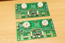
The smaller amp would have likely used the Russian KT88's or some tasty NOS JAN GE 6550s that I have, probably in triode mode with adjustable fixed bias, based on the breadboard design seen here:
Mounted in the Landfall Chassis seen in post #20 of the bias servo thread:
https://www.diyaudio.com/community/threads/bias-servos.404119/#post-7484857
Wiring a pair of tubes to a suitable driver and power supply is not trivial, but not rocket science for those who have built tube amps for many years. Wiring 4, 6 or 8 high Gm tubes to a single driver circuit and keeping them all happy with each other is NOT easy. Early experiments with a dozen (2 banks of 6) used but tested and somewhat matched 6AQ5's failed in a red plate meltdown, as did an attempt to run 8, then 6 X NOS 13GB5's in a push pull amp. At least the 13GB5 amp worked for a while. The 6AQ5 amp was never stable.
Simple bias pots for each tube will not work, especially as the tubes age. That's why the "bias servo" or other suitable control means becomes a necessary and critical part of the complete amp, as does a complete power supply system that would produce 625 volts at up to 3 amps.
I developed a microprocessor controlled simple SE tube amp for a design contest back in 2007 / 2008. I plan to expand on this concept using a modern 32 bit Arduino compatible CPU. Of course, the opportunity to blow stuff up with a mixture of high powered old tubes, a microprocessor, and some of my mediocre coding skills a is real big (nearly guaranteed) here, so I must go back to the breadboard stage and start real small with tubes that I have a lot of, and that cost less than $1. I have a lot of 6DG6s (25 watts per pair) and 25DN6s (100 watts per pair).
Today's task is to reassemble my breadboard and get some sound out of it. I need to choose between a pair of hacked and abused UD boards, or a pair of built years ago and never used or tested boards. All 4 were built at the same time.
Those two big black OPTs were made by a known con artist named David Lucas who ripped off lots of people with ESL speaker panels, books and "Handwound Transformers." They will be "tested."
Attachments
Hey WG_SKI.....For your input re the screen voltage......The problems occur at idle.....not whilst playing music....there is a paper on the net somewhere regarding reverse screen current......The transmitter fraternity are well aware of his....if i can find the paper I will post a link, but it states that this can occur in all tetrodes to a greater or lesser degree.....the EL/PL 509/519 Seem to be pretty much immune to it, the paper states that this can occur especially when the screen voltage is regulated via a series pass regulator..as I was using no more It advocated the use of gas tubes which can sink the reverse current....will try 125 volts and see how that suits....the amp was so powerfull...never heard bass like it...so its going to get a rebuild.....The output tx was wound by Majestic in the uk.....A recent quote I had for a 1200 watt Ultralinear was 980 GBPAccording the the curves, it would only NEED 110 on the screens to make the required current (640V/250R = 2.56 A). They will supposedly do WAY more than half an amp apiece even at 110. Thats about where the smaller ones are at 125. If this is true, 175 is way the heck too high and would result in excessive g2 current. I had 26DQ5’s giving me over half an amp apiece in a real world build at 125V g2, so there is no reason to doubt these tubes’ capabilities.
I would have expected a custom output TX to be at least three thousand. If I can get a $200 solution to work…… The issues are voltage handing (check), DC balance (check), and HF response (unknown for these units). The only way to know is make hardware.
Huggy - “Don’t try this at home?” Wouldn‘t dream of it. Hardware will only be constructed/used at the new shop facility, assuming we ever get there. It’s about 15 feet from the “house”, which has a similar look to it. I was in the middle MOVING the SHOP when I had my little recent mishap. This resulted in too much time on my hands, which is a bad thing for an “engineer”. Once there I’ll be divining time between indoor construction, amp building, and work. But far better than trying to do anything in a facility that I’ve outgrown.
Oh, you mean g2 leakage. G1 leakage does the same thing - cause run away when the grid circuit resistance is too high. The k-follower tails take care of that. That’s why I insist on having them there. Designers will often insist that “You dont need all that”, but experience has proven otherwise. Mosfet vs tube is open for debate, but the need is very real.
The solution for g2 leakage is simple - provide a minimum load for the g2 regulator. Leakage happens and it tries to force vg2 higher, but it can’t because the load resistor can eat this and vg2 stays in regulation. I first ran into this “issue“ with GaAs FET amplifiers. The gate power supply needs to be able to both source and sink current or you can get bias runaway. Customers HATE doing this and just want to use an LM337 - and run into trouble. And you just can’t get it through their thick heads that wasting a little power on the vg supply is a good idea.
The solution for g2 leakage is simple - provide a minimum load for the g2 regulator. Leakage happens and it tries to force vg2 higher, but it can’t because the load resistor can eat this and vg2 stays in regulation. I first ran into this “issue“ with GaAs FET amplifiers. The gate power supply needs to be able to both source and sink current or you can get bias runaway. Customers HATE doing this and just want to use an LM337 - and run into trouble. And you just can’t get it through their thick heads that wasting a little power on the vg supply is a good idea.
Hey yes, a bleeder resistor from screen to cathode/ground would seem to be the answer offered....Eimac data sheets,/ application notes suggest the same with a series pass regulator which is commonly used in audio amplifiers to supply the screens, other than this problem the 6LW6 was/is fine at 175 volts on the screens at 850 volts anode......power flies off them......when I rebuild to be on the safe side i will fuse the cathodes.....some experimentation re fuse type...slow verses quick blow and values will be required.....as you calculated...I have had them swinging over 500ma off their cathodes in real time ....Playing music with a multimeter plugged in....no where near clip....this was of 4 amps rectified at 850 volts....You should get close to 175 watts at 700 v loaded with 150 on the screens
Leakage might not be the right word, but never mind the semantics the phenomenon is real and can happen in nearly any tetrode or pentode under the right conditions. The " bleeder" can't be too small or a tube meltdown or arc can occur. In an audio amp the plate voltage can be pulled below the screen grid voltage on music peaks. During this time the screen current can surge to tens of milliamps or more. If the amp is pushed into clipping for a length of time the screen dissipation will be exceeded and the screen may get hot enough to emit electrons. On the next half cycle peak the plate voltage will be at or near twice the B+ voltage and any electrons emitted by that glowing screen grid will travel to the plate. This condition can escalate to a melted screen grid, or arc over in a few milliseconds. This is especially bad if the plate supply is considerably higher than the screen voltage.Oh, you mean g2 leakage.
I turned a couple of 6BQ6GTs int flash bang grenades with some screen drive experiments resulting in over 100 watts of audio from a pair of these tiny tubes. I had blown tubes and stains on the test board where the mosfet drivers used to be before I figured out why this happened. This was about the time that I abandoned screen drive. Later I discovered that a simple 1N4007 in series with the screen stops the blow ups but doesn't solve the real problem.
Part of the management of this issue in my big amp will have the microcontroller keeping an eye on the screen current in each output tube.
Lots of crazy experiments along these lines occurred when AES exited the NOS tube business and sold off much of their inventory at cheap prices. Some of that can be found in this 15 year old thread:
https://www.diyaudio.com/community/threads/tube-sale-at-aes.128533/
My UNSET (P ch mosfet follower in the cathode for drive) circuit that I have been using for most of my recent work has a fuse in the cathode. I use a fast blow 1 amp with 6LW6 and 26HU5's. It will blow if something results in an overload, but will explode right off the board if a tube arc occurs. Two tube arcs, both with 6HJ5s that shattered, one violently also made the fuse vanish into glass dust. I did subject the poor tubes to some bad math resulting in a short term dissipation of several hundred watts when it was already hot. The fuse is the little green thing that's about the same size as a 1/4 watt resistor just above the vent holes for the mosfet heat sink.
Attachments
Something I had done on the 6550 amp was to put screen current limiting into the regulator. A resistor in the drain circuit, to allow the regulator to be stiff and have a low Zout under normal conditions, but act like a big screen stopper is there if the current it too high. It works. I try to run it with no load and crank it, and Vg2 drops like a stone when driven to clipping. Ran it that way for over an hour by mistake and didn’t see one glowing screen. The flyback diodes saved the OPT from overvoltage, too. Those will be necessary here -along with the output zobel.
I rigged a similar resistor in series with the drain on my full size UNSET boards. Not only does it save the tube, but it takes the heat and the SOA failures off the mosfet - Zener "regulator. " The real fun stars when the mosfet shorts and puts 400 volts on the screen.
My earlier solution was an SCR crowbar for OVP in case of mosfet failure. Unnecessary with the better solution.
But still on the regulator board.
But still on the regulator board.
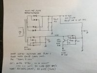
I was kind of joking around in the other thread when I mentioned wanting Phase Linear Series 2 meters on one of these things. Then I got to thinking maybe make it do something useful. Like display peak and average cathode currents on the same bar graph. I could see if things are drifting overall (the servo would keep balance) comparing the pairs, and give a warning on excessive peaks. Perhaps trigger shutdown. I have a whole tube of LM3914’s. Just need some LEDs and more LM358 op amps. Uniformity between 6 parallel displays would be good, discrepancies bad. And it would look cool as hell in operation.
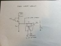
The problem with screen currents is they are not ground referenced. A bunch of flying wires having capacitance to the universe is never good, not to mention the common mode voltages. Dropping it down by a factor of 100 invites noise issues. What’s needed is an excess warning anyway, so why not an optoisolator? Sense the drop in part of the stopper resistor with the LED, and couple the transistor to whatever circuit. Integrate for an ”I told you so” shutdown.
The problem with screen currents is they are not ground referenced. A bunch of flying wires having capacitance to the universe is never good, not to mention the common mode voltages. Dropping it down by a factor of 100 invites noise issues. What’s needed is an excess warning anyway, so why not an optoisolator? Sense the drop in part of the stopper resistor with the LED, and couple the transistor to whatever circuit. Integrate for an ”I told you so” shutdown.
Attachments

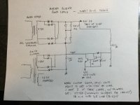
The UNSET circuit design uses all positive supplies. The positive bias supply is derived from the screen supply so that a shorted mosfet regulator actually cuts off the tube even though the screen is at 400 volts or more. Bias is applied to the cathode while the control grid stays at a fixed DC value. The first board that I built had a 250 volt electrolytic in the screen supply which didn't last long and made a mess on its way out. There's a 450 volt cap in there now, but it has not been "tested."
I have used the LTC6101 high side current sense amp for turning a current flowing through a high voltage circuit to a ground referenced voltage. Look at the 500 volt circuit on the bottom of page 18 in the data sheet. There are similar parts from other vendors too. Hopefully there is one that is not SMD, if not I use adapter boards from Amazon. I don't know if it's fast enough to track the screen current at an audio rate or how well it would live directly in series with a tube plate in a BIG amp. I used it in a DIY power supply, that never got finished once I got a couple big supplies off of Ebay cheap.
Slap a few series diodes across the sense resistor so that the whole chip doesn't become a stain on the PC board if a tube arc blows the sense resistor in half. Diodes almost always fail to a short.
Attachments
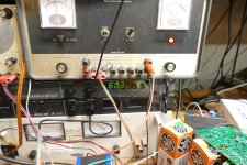
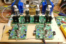
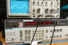
It took nearly a week, but I put my breadboard back together then proceeded to squeeze a pair of 26HU5's hard to see what I could get out of them.
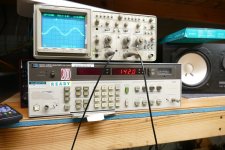
I set the screen supply at 175 volts and tried my old Fluke 407D from the late 60's as the plate supply but it could not power a single channel past 100 watts without going to convulsions. I swapped in a Sorensen switcher that goes to 600 volts at up to 1.7 amps. Full crank was 602 volts.
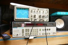
With the 3300 ohm Edcors "properly wired" to reflect a 3300 ohm load on the tubes, I "set the controls for the heart of the sun" and pulled the trigger. I just turned up the oscillator until the Audio Analyzer read 3% THD and then keyed in the "watts into 8 ohms" sequence. The display read 142 watts. Plate supply current was 460 mA for a total efficiency (tubes, mosfet, and OPT) of 51.3%.
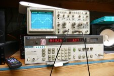
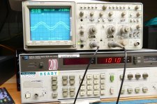
Then I tried miswiring the Edcors to reflect 1650 ohms on the tubes. Power at 3% THD was 202 watts with a plate current of 771 mA for a total efficiency of about 43%. The 26HU5's really don't like the 412 ohm per tube load.
This setup will be used to develop a power supply capable of running two channels. Then it will be used to develop and test a controller for power up sequencing, auto bias, soft power limiting as clipping / excessive screen current is detected, and cathode current monitoring for each output tube with auto shutdown if things go wrong, several other neat ideas that I have not yet fully tested.
If it survives all the abuse, I'll put in a nice rack mount chassis and use it. When it's time to build the big one, I'll build all new boards and basically duplicate the output stages 2 or 3 times.
I set the screen supply at 175 volts and tried my old Fluke 407D from the late 60's as the plate supply but it could not power a single channel past 100 watts without going to convulsions. I swapped in a Sorensen switcher that goes to 600 volts at up to 1.7 amps. Full crank was 602 volts.
With the 3300 ohm Edcors "properly wired" to reflect a 3300 ohm load on the tubes, I "set the controls for the heart of the sun" and pulled the trigger. I just turned up the oscillator until the Audio Analyzer read 3% THD and then keyed in the "watts into 8 ohms" sequence. The display read 142 watts. Plate supply current was 460 mA for a total efficiency (tubes, mosfet, and OPT) of 51.3%.
Then I tried miswiring the Edcors to reflect 1650 ohms on the tubes. Power at 3% THD was 202 watts with a plate current of 771 mA for a total efficiency of about 43%. The 26HU5's really don't like the 412 ohm per tube load.
This setup will be used to develop a power supply capable of running two channels. Then it will be used to develop and test a controller for power up sequencing, auto bias, soft power limiting as clipping / excessive screen current is detected, and cathode current monitoring for each output tube with auto shutdown if things go wrong, several other neat ideas that I have not yet fully tested.
If it survives all the abuse, I'll put in a nice rack mount chassis and use it. When it's time to build the big one, I'll build all new boards and basically duplicate the output stages 2 or 3 times.
Attachments
Last edited:
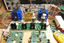
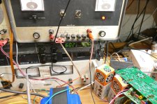
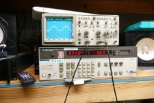
For tonight's testing I dialed back the B+ to 550 volts since this is about what I get with one of the big Antek toroids that I have. Then I put some tubes in the second channel and fired up both channels at once. Power at 3% THD is 115 watts on one channel and 118 on the other. Dialed back to 100 WPC, I get about 2.2% on each channel with both being driven. Total screen current (4 tubes) was about 30 mA. Total plate supply current was 726 mA. THD at 10 watts was 0.86 and 0.66 at 1 watt with the idle current set at 30 mA per tube.
After beating on it for about an hour the idle current had risen to about 40 mA per tube. This is due to the change in mosfet characteristics when they get hot. The heat sinks were too hot to touch, and the dummy load resistors were hot enough to melt the insulation on the cheapie clip leads I was using to hook stuff up. There were hundreds of watts from 4 different power supplies all being turned into heat and after an hour EVERYTHING was HOT! Even the scope probes. Thermal tracking and management goes on the list of things to implement in the microcontroller. After some more serious thrashing the total idle current had leveled off at 180 mA, about 45 mA per tube, but a quick finger test on the heat sinks tells me that it was not evenly distributed.
So with all the engineering stuff out of the way, what's left to do? OH, how about some speakers and a CD player. From the first note out of the speakers I realized that this thing is the polar opposite of a 300B or other DHT amp. Transients are sharp and snappy. The Bass is big, and tight. The alto sax on Take Five is inside the audio analyzer. The other instruments are spread out in front of me. A little nudge on the volume knob reminds me that this amp could probably scatter my 30 year old Yamaha NS-10M Studio monitors all over the room if I dimed the knob. This is a very nice sounding amp. It's also a very loud amp and I never got past 2 on a zero to ten scale with the volume knob. I spent the rest of the night playing CD's.
The idle current had leveled off at 175 mA after I pointed a small fan at the heat sinks. Loud music made the total plate current wander from 180 to 220 mA, so the amp was never taxed, or even came close to medium power. The screen supply meter sat on about 10 mA total and bounces about a mA or two on bass notes at loud volume. It's a two inch meter that goes to 300 mA, so I have no idea what the current really was, but it was very low. The cathode voltage runs about 50 volts and the screen gets 175 volts, so the tube screens see 125 volts. With the plate voltage idling at about 540 volts, the electrons don't stop at the screen grid.
Attachments
George, I must say I envy your fearless approach to circuit testing. Very inspiring for the rest of us who don't have the guts😀
I've been looking at your UNSET topology as a possible way to squeeze the best possible performance out of my beloved zero-bias DHTs. It should be possible with some changes in DC levels and a Fet buffer between the feedback voltage divider and the control grid.
If I ever decide to give it a try, remind me to buy some russian or chinese 811A as test mules instead of my rare 1930´s triodes😱
With a bit of luck & a helping of brute force a power line toroid will get to some satisfactory LFs.People (including me) have successfully used power toroids for output transformers
But getting any half decent HFs thru is similar to pushing a rope up a hill. The leakage reactance always gets in the way.
But many folks like the result anyway. 👍
- Home
- Amplifiers
- Tubes / Valves
- Musings on the design of “the big one(s)”