Tannoy TS8 hums when set to Auto

I wonder if someone could advice me, please. Subwoofer Tannoy TS8 started to make humming noise, I took it apart and found capacitors C428 and C427 (in EMI circuit) swollen. I replaced them and it worked fine for some weeks. Now it hums again, but only when switch S200 is set to "Auto". When switched to "On", it works flawless. Anybody any clue? Thanks in advance.

An example of TL vs BR ?

i snatched up the resent recommended venTed box for a rockford fosgate 12” p3…. It just so happened to fit in the HR suggestion/thumb rule for port tuning/length/hopefully incompressible mass/shape?

kinda funky high tuned car audio junk but it fit the bill.

any suggestions on what to look at ?

Attachments

  • 6E610EE7-94E0-4C0B-90FA-479632D32AED.png
    6E610EE7-94E0-4C0B-90FA-479632D32AED.png
    54 KB · Views: 98
  • F833634C-1762-4DE6-A0E6-1983DC23A5F0.png
    F833634C-1762-4DE6-A0E6-1983DC23A5F0.png
    3.1 KB · Views: 81
  • 0AE27536-FBBA-46F9-8D21-088B6100ECF5.png
    0AE27536-FBBA-46F9-8D21-088B6100ECF5.png
    9.4 KB · Views: 85
  • 6EFC04A5-CAB2-4EC0-A265-5DF427E1F904.png
    6EFC04A5-CAB2-4EC0-A265-5DF427E1F904.png
    14.9 KB · Views: 92
  • 798E8EED-83DF-4ED4-A7C1-D529262FD6CA.png
    798E8EED-83DF-4ED4-A7C1-D529262FD6CA.png
    5.3 KB · Views: 84

Parasound HCA-2205a - no output from any channel?

Hi everyone,

I have the above mentioned amp which was working fine but overnight, I now have no audio from any input/output? From the front-panel it looks fine and it is not in any kind of protection mode. I've measured all the output fuses on each amplifier board and they are fine too with next to no DC offset present on any output.

I can't seem to find a service manual/cct diagrams for this so any help/advice would really be appreciated.

Thanks

What is the process for recessed tweeter design?

Hi everyone,

Something I'm a little curious about is stepped baffle speakers. These are speakers where the tweeter (and sometimes more) is recessed from the woofer in an otherwise conventional design. That is, not in a wave guide or horn. I often see these in two way designs, Troels Gravesen has a couple of such kits as well, like this one:

1710427528619.png


When I first saw them I thought "oh, well this must be to create a perfect impulse response, like Thiel" but these speakers often lack this particular feature. So, if not for this, I wondered "well, maybe it's so they can use a certain order filter more easily" or "maybe it's so the off-axis response is consistent?"

So I wonder, at a very high level, what is the process to think about designing a speaker with a stepped baffle?

1. Decide stepped baffles are cool
2. Build the cabinet
3. build the crossover

or is it more:

1. Decide to use (as an example) 4th order LR crossover
2. Pick drivers
3. Find acoustic offsets
4. Design cabinet for ideal phase matching

Or is it more about using 2nd order filters AND keeping the drivers in positive polarity??

Thank you for any insights.

Coral Flat 8 II basket dampening

The Coral Flat 8 is a good driver indeed, but the Beta series is even better, having molded baskets instead of the stamped baskets of the Flat series.
A stamped basket resonates heavily when struck with an object, and the same goes for my Flat 8's.
They sing like a bell when struck, so I decided to try my hand at dampening the basket with some rubber dampening material.
The rubber sheet has adhesive of one side, but it doesn't stick well to metal so cable ties are needed to ensure good contact between the basket and the rubber.
Unmodified driver: -Rings like crazy when struck.
Modified driver: -Totally dead when struck, no resonance at all.

coral flat8.jpg
  • Like
Reactions: adason

Anthem MCA20 - Reduced Dynamic Range

So I picked this and a preamp up for a pretty good deal. When I play the amp it sounds great - crystal clear, but it doesn't pull that really low bass. I ran an A to B with my McIntosh MAC6700 and there was on audible difference in the amount of low bass produced. I used the preamp section of the MAC6700 for the Anthem too. Is there something I could replace in the amp to remedy this? It is probably nearing 20 years old. Would replacing the bypass caps or the power supply caps improve the bass output? I hate to tear it open, but I am a little bummed out. I am not even sure where to start, or just ignore it and pair it with some bookshelf speakers that don't hit the low bass anyway.

Thank you.

-Geoff

Simulation software for horn with phase plug

Hi guys.
I would like to design phase plug horn, similar with conception funktion-one, but differ horiz and vert dispersion angle. I know that task is not easy. I well know and can works in 3d max and solid works for make a polygonal and hard -body model. But i doubt for selection of acoustic simulation software. For now, i see to several software for this: Akabak, Comsol Multiphysics, Ansys.
Maybe, some of you know, what of this or other software is more able for complete this task? And what series of doings must be , after create hard -body model? Thanks.

photo_2024-03-25_10-17-45.jpg
photo_2024-03-25_10-17-50.jpg

2 Octal splitter/driver combinations for KT88 amp

Hello everyone. I'm really enjoying getting back into this, and all of your help. I was wondering if you wouldn't mind sharing some of your tried schemes for a 2 octals splitter/driver combination. I'm going to be driving KT88 or 6550, and have around 500V B+, -85v bias to utilize. I'm seeing a lot of similar things here lately, but with 9pin tubes, and didn't want to hijack a thread. I'd really like to have some current behind my drive this time around. I've thought about 6sn7/sl7 combinations, cathode followers or mosfet followers, but I figured it was silly not to ask and see some of what you all have come up with.

Thanks much- Loren

Has anyone tried setting the subwoofer frequency above 100 Hz?

I have added two subwoofers to the main speakers, running them in stereo mode and crossing them at 100Hz @ 24dB/oct. Since the electronic crossover used, ADS 642ix, has fixed crossover modules, not continuously variable, and there are 4 alternative modules: 65Hz, 100Hz, 130Hz, and 170Hz, all @ 24dB/oct. slope, has anyone ever tried setting the subwoofer frequency above 100 Hz? Can you describe the sound if using 130Hz or 170Hz settings?

At present, I could describe the sound character of the 100Hz setting as giving a lot of bass head punch, which sometimes causes irritation and fatiguing. I'm not sure would the problem solve if changing setting to 130Hz or 170Hz?

The 6V6 Lacewood Amo V2.0

https://www.cascadetubes.com/the-6v6-lacewood-amp-v2-0/

I finally finished the amplifier. No hum, and it sounds clear and the bass is deep and good.. Playing Sting with the album "If on a winters Night". Great album with lovely sound, good production. This amplifier turned blue, tried to find the same blue color as Edcor's output transformers, and hit...like almost-ish? Has red amplifiers, black, green, and then this one just had to be blue. Wondering what color the next amplifier will get? thank you all for a great forum, with lots of good people!

20231126_191601.jpg

Attachments

  • 20231126_191549.jpg
    20231126_191549.jpg
    387 KB · Views: 1,011
  • 20231126_191610.jpg
    20231126_191610.jpg
    416.9 KB · Views: 131

ADC driver for best objective performance with ES9822PRO?

In most cases, including the evaluation board from ESS, OPA1612 is used to drive the inputs of the ES9822PRO. It is a tried and proven solution, working quite well.

In some cases, a fully differential amplifier gives a simpler design.
The QuantAsylum QA403 apparently use the OPA1632.

Has anyone here tried to use OPA1632, or perhaps the newer OPA1633 and compared the performance to the OPA1612 solution, in terms of noise and distortion, including distortion versus frequency? Noise can probably be simulated rather accurately, but distortion is more difficult to predict.

I am looking for objective performance, so no discussions on audibility please!

DIY McIntosh DAC card

I often saw people sold McIntosh DA1 DAC card/module after they upgraded to DA2. I’m thinking whether it’s worth buying the DA1 module and diy it for using without needing to install to McIntosh’s amplifiers. I’m talking about building a power supply and adding output RCA cables. But I’m not certain if it’s as easy as describe because I don’t know if the module needs some special software to config it or not. Does anybody have information about this? Has anybody ever done or seen it? Please share your thought or experiences.

Attachments

  • IMG_8004.jpeg
    IMG_8004.jpeg
    40.9 KB · Views: 113
  • IMG_8005.jpeg
    IMG_8005.jpeg
    56.8 KB · Views: 119
  • IMG_8003.jpeg
    IMG_8003.jpeg
    56.2 KB · Views: 93

THD and IMD calculation in nonlinear systems

As part of the insights into the behavior of distortions through measurements and simulations, I came across an aspect, actually secondary to my study but which intrigued me enough. This is the calculation of the THD and IMD in non-linear systems (in simpler words, our audio amplifiers…).

In short, the modeling of these systems shows that among the new harmonic components that are introduced in the output signal (HD2, HD3, HD4 ...) there is also a component, HD1, "hidden" in the fundamental (H1). This component is naturally not detected in the measurements, as the instruments read H1+HD1, they cannot be distinguished, and refer the level of the other harmonics to this value. But the computational models say that there is…

As quantity, HD1 is not exactly negligible: it can be up to 10dB higher than the third harmonic (HD3). And it must be considered distortion, since it depends on the cube of the signal level (or higher powers in the presence of other harmonics). This causes dynamic compressive or expansive effects on the signal and phase shifts.

Now, beyond the questions on the audibility of these effects, this aspect also causes errors in the calculation of the THD which, "losing" this component in the numerator of the classic calculation formula (HD1 is not there...), is underestimated by up to 10dB in the presence of odd order distortions (taking HD1 into account or not in the denominator causes negligible errors, at least in the "normal" case of audio device distortions). In other words, the THD is not representative of all the nonlinear distortions introduced by the system. Therefore, even the comparison of the THD (and also of IMD, SINAD etc.) of different devices loses significance when these values are close to each other.

I reported more details in these two posts:​


Has anyone come across these aspects before?​

Parasound HCA-1200Mk2 turns into standby

Hi Experts,

my Parasound HCA-1200mk2 (purchased 1994) shows the following behavior:

Turning on from cold state shows the normal behavior, first the red standby LED for a few seconds, then turning to green LED, relays click, then fine music.

After an hour or so, with music at low volume, the left channel disappears with a relay click, the power LED turns to red standby, the right channel still plays music for a few seconds, then after another click of the right channel's relay, also this channel is switched off. It seems to be a temperature issue. Both channels heat sinks have normal temperature, lukewarm, not more. In this state, with the standby LED red, here is no DC bias on the outputs (measured prior to the output relays, at the channels PCB where the 0.33 ohms are connected to the common output rails.) It also happens without input signal, hence no input bias. The bias voltage across the emitters 0.33 Ohms is 10mV +/- 2mV, regardless whether in active or standby. When switching off the HCA, after a pause of an hour or so, I can repeat the same thing.

The only modification/repair the HCA has seen:
Main power switch replaced 15 years ago.
New power caps 10 years ago. Replaced the 4 x 15,000uF 80V by 4 x 22,000uF 80V.
Overload LEDs never seen active.
Driving a pair of Infinity Kappa 8i with renewed crossover.

I have to mention that it is the European 230V version.
The power supply and transformer differs from the schematics.
I have two transformers instead of one.
There are fuses in the signal output path towards the relays, they are not shown in schematic.
I could not find the two fuses on the secondary side of the high power transformer outputs towards the rectifier D001, as shown in the schematic.
There is one fuse towards the low power rectifier D002.

My interpretation:
The main power supply is ok (power transistor collector rails have +/- 75V)
The channels PCBs are ok. No DC offset on input or output.
I think, the suspect is the lower power supply on the center PCB for the protection circuit, around C011, C012, C013, or the protection circuit itself.
Seems it enters standby without any need....?

Any advice or idea?

Blown Parasound HCA-2205a

I purchased a Parasound HCA 2205a off eBay that was listed as used, in good working condition, but when I plugged it into the outlet, it sparked at the receptacle and inside the chassis. I opened up the chassis and found this:

Now all five channels are in standby mode. I took it to an Authorized Parasound Service center and the tech quoted the fix at $275. He looked at it for about 10min. I figure replacing the cap and fuses would probably fix the problem. What do you guys think?

Attachments

  • IMAG0129.jpg
    IMAG0129.jpg
    815.5 KB · Views: 791
  • IMAG0137.jpg
    IMAG0137.jpg
    781.8 KB · Views: 837

Arduino controlled DSP for my project - FreeDSP?

I have a broken AVR receiver with faulty digital board so I decided to turn it into a DIY projekt. I want to reuse it's power amp section (7 channels), FM/AM tuner, VFD, buttons, remote, and all the connectors (sub output, SPDIF in/out, analog inputs, USB, antennas etc.). The plan was to use an Arduino to control everything including power amp and power supply relays, and Raspberry Pi running Volumio. But the missing thing is the preamp/DSP. Minimally I need a multi input / multi output I2C controlled module with volume control, minimum 3-band EQ and input selector. But ideally I would like to have parametric EQ, loudness, subwoofer out, SPDIF in/out, HDMI in, completely configurable inputs and outputs etc.

I have some experience with soldering, Arduino and I2C module boards. I already have at home some simpler boards with volume control, tone controls and 4 channel stereo input. But it's not sufficient for my project, sound quality is meh and I'm struggling to find any other better board.

Until I didn't stumble upon the FreeDSP project. ADAU1452 seems to offer everything that I need and much more, but I'm wondering if this is too much for my knowledge. Good thing is that there are many examples with Kicad files, schematics, Sigma config and everything so my plan was to use all this info to try to build something for myself. I would like to build a custom board that will fit instead of the original board into my AVR and re-use all the connectors.

Is there anything better/simpler for my use case? If not, what is the best way to start diving into this? Where to buy parts? Mouser? I guess having an evaluation board to experiment first would be the best, but those are too expensive so I would probably be brave enough to build my custom board immediatelly. I guess I should start by learning Kicad and everything about FreeDSP and Sigma, right? How hard is to get those things working? Is the sound quality in pair with DSP that is usually built into AVRs?

Currently I'm looking to combine PiDSP and Aurora to get everything that I need. Having ESP32 onboard seems nice for OTA programming. And I can connect my RPi directly via I2S.

For now, my biggest question is, once I "design" the DSP in Sigma, how do I send instructions to it? Eg. if I add a parametric EQ, can I use ESP32 or some other Arduino to send commands via I2C to change actual values for each EQ preset?

Any info, link, suggestion or other things on how to start with this is welcome.

Clarion ADCS-1

Ultra rare Clarion Digital dream system For Sale.
The Entire System was removed from my car circa 2012 and has been placed in there original boxes since then. Been hard to let it go, but its time...
Included are as follows:
1x Clarion X-DP1 Digital Processor
3x X-DA1 D/A Converter Module
4x X-DP1 Metal Brackets (4)
1x 5m Fiber Optic Cable
1x Small Owners Manual
1x X-CD1 Control Unit
1x Small Remote Control
1x RCB-051 Remote Control
Original Boxes

Asking: $1200+Shipping

Design Check/Input TABAQesque with TB W5-2143

I would like to get feedback on this design from those who are willing. TIA.
Goals:
  • More compact than the TABAQ for 5" shown here TABAQ design (S1 - S3 is much smaller than usual Sd rules of thumb)
  • Do not exceed xmax below the unloading frequency (xmax with damping is @ 40 Hz)
  • More low extension than a simple BR
  • Start with a Tang Band W5-2143 (not great xmax but upper response looks flat) TB W5-2143

Results (so far, not great):
TABAQ MLTL Tang Band W5-2143 - 4 - B.png
TABAQ MLTL Tang Band W5-2143 - 4 - A.png
TABAQ MLTL Tang Band W5-2143 - 4 - C.png
TABAQ MLTL Tang Band W5-2143 - 4 - D.png
TABAQ MLTL Tang Band W5-2143 - 4.png
WinISD BR Tang Band W5-2143 - 4.png


Observations:
  • The BR in WinISD has better SPL (+6 dB) at the same xmax limitation as the MLTL.
  • The MLTL is a little better on its -3dB point but not much.
  • Looking at the MathCAD worksheets for the TABAQ (in the long TABAQ thread) it also has a SPL of about 90 dB at xmax. Its extension is better (due to more volume?) but is not hugely better.
  • Peak group delays are similar
  • The total volume of the BL is 17 liters (WinISD) and the MLTL is 18 liters (Hornresp).
  • I played around with port length and settled on the length that provided the flatter response at the bottom (below 100 Hz or so). It was possible to get more extension with more port length but the width of the 1st bandpass response started to suffer; the roloff after ~100Hz started to suffer.

What am I missing here? I do not see much benefit if any to the MLTL over the BR as I have modeled it. I AM NOT BERATING THE MLTL; it is clearly a proven approach. I am wondering what I may have missed in my simulation that limited the potential in the MLTL approach since I am not a long-time user of Hornresp.

I have read through a lot of the TABAQ thread, and used Hornresp to model several different MLTLs, TLs, and tapered TLs trying to come up with a design that beats the BR but I can't get there for some reason I do not understand. If so, then I could use help with my modeling and/or optimization approach. Again, this is not an attack on the MLTL; I only mention this again since some here seem to get quickly offended if there is even a suggestion of such a thing.

Thanks in advance

Looking for a good wire dispenser

I'd like something that can hold half dozen rolls of wire, and grip the ends so I can easily grab and pull however much I want, like a packing tape dispenser. I also worry about the spools coming undone. Most of what I see is just a rod that goes through the spools, with no particular guide or control for the wire feed. Am I imagining a product that doesn't really exist?

AQ Audio AQ2200

Hello, good evening friends, I am here, again with another topic. Now with an AQ Audio brand amplifier model AQ2200, the problem here is that the source fets flew and as a starting repair the fets (irfp064n) and impulse transistors were replaced, as well as gate resistors, in the end the signals were checked and everything is perfect, 1 Irfp064n is placed for each bank and everything works perfectly.... but however, when I proceed to place all the missing fets in the source, the current consumption increases drastically, I have already done tests for damaged fets, all They are from the same batch and are original, I cannot find the reason for the high consumption and heating of the irfp064n, I thank you and thank you very much for your support, tomorrow I will upload photos of the board.

Musical Fidelity A1 Left Output Problem

Hi guys,
i am trying to fix my amp. Both channels are working, but the amp is extremly hot after few minutes.
Resistors R1 and R2 (0,47ohm, 2W) are burned. I changed them for 5W so that i can make some measurements.
Power supply voltage should be around 24V, but when I turn it on its about 22V and its going down to 19V.
I had 1V Dc on output of left channel.
I checked all transistors, elcos and resistors and everything looks fine.

I disconnected Emitter and Base from TR9 and TR10. Now power supply voltage is around 24V and resistors arent hot.
With R6 and R11 3,9Mohm and R30 and R31 0,22ohm i should get sth about 700mA BIAS current.
Why I am getting much more?

Attachments

  • IMG_20240317_115510.jpg
    IMG_20240317_115510.jpg
    420.8 KB · Views: 205
  • IMG_20240317_115608.jpg
    IMG_20240317_115608.jpg
    346.5 KB · Views: 160
  • IMG_20240317_141206.jpg
    IMG_20240317_141206.jpg
    418 KB · Views: 186
  • a1_schematic.jpg
    a1_schematic.jpg
    303.9 KB · Views: 206

For Sale Fulton Premier Modular J Speakers

Would anyone be interested in a winter project?? I have this set of Fultom Premier Modular J Speakers looking for a new home. They have been in storage for many many years. They appear in good shape. And should work. but could use some cosmetic restoration. Photos are of the same model. full photos of the actual speakers will be sent to a serious buyer. they are difficult to get to at the moment. but if someone is very interested. I will dig them out and get proper photos.
I have a full set of manuals with them as well. Long story of how I ended up with them. But I was not the intended owner. I don’t have the room to keep them and they have to go. $500 and they are yours. Pick up in Bloomington MN or can put on a pallet and ship VIA Fastenal store to store shipping for a reasonable price to most places except California and northern NV. those areas would have to ship by Truck.. Please contact me if you have interest and I can give you the full details.

Here is some info about them

The Modular series Premiere features accurate vertical phase alignment, precision horizontal speed, and time domain alignment of its 7-way, adjustable, line drive system. It will play from Bach to Rock on any quality amplifier with 40 to 1000+ watts of available power. Frequency response: 13 Hz to 80 KHz of complex musical information. Impedance: 8 ohms.


The FMI Modular System is composed of three speaker modules, plus an optional cover cube. Each module has been designed to fit a specific position in the J configuration. There is a large base woofer cabinet, a Fulton model FMI 80 speaker used as the lower midrange module, and a tweeter box upper module, containing a 5" midrange, a T35 horn tweeter and a small cone super tweeter crossed in above 20,000. This later model with dynamic tweeters was created when the electrostatic array used in the J Modular was no longer available.


" The primary objective behind the development of the Premier has been to build a system that is absolutely faithful to the sound of actual music, scaled to your listening room. This has required complete objectivity in listening and a desire for perfection in every phase of design and production. It has also required exacting attention to such details as transient purity, perspective, proper dynamic intensity, open, free flowing airiness, accurate re-creation of the correct tone structure, size, and vowel color of each individual instrument and voice, as well as the precise spacial imagery, sense of depth, thrust, balance and vitality we normally hear in live music. Countless hours of critical listening and exhaustive experimentation has transformed these concepts into a speaker system that has earned a unique position for itself among music lovers in the audio world." Robert Fulton


Additional Information:

See what Stereophile said about the previous version of this speaker.
https://www.stereophile.com/standloudspeakers/0973fulton/index.html
https://www.stereophile.com/content...el-80-j-modular-loudspeakers-more-reviews-jgh

2068925-d0c04ec4-fulton-premier-modular-speaker-fmi.jpg


2068926-34fccb1f-fulton-premier-modular-speaker-fmi.jpg

Reliability of germanium transistors when overdriven

Hi all, time for my bi-annual post 🙂

I have been using the darlington rangemaster design for years in a Tony Iommi style boost pedal. I am noticing that maybe once a year or every other year I have to replace the MP44 soviet made germanium cans for seemingly no reason. As far as I know Tony never had to have the rangemaster serviced in the 10 years he used it, I am wondering if his was built better then mine or the cans were just swapped for silicon.

I understand germanium REALLY hates temp swings, I remember a long time ago I saw a circuit using a diode between the emitter and base (I think) with both the transistor and diode attached to a heatsink so the diode will thermally compensate for the bias but I forgot what that is called.

Is there a way to make this circuit more stable?

Here is the circuit (Ignore the way I bungled up the 10k) I replaced the volume pot with a 10k resistor since I always run it dimed anyways.

Any advice greatly appreciated.

Attachments

  • 20240302_091316.jpg
    20240302_091316.jpg
    262.3 KB · Views: 180

Need Service Manual for Counterpoint NPS200

I own a Counterpoint NPS 200E power amplifier. The left power transistors need to be replaced.

Now I need to fix it and adjust the bias and offset and for that I need a copy of the service manual or the power stage schematic and instructions for adjusting the bias and offset.

Michael Elliot has disappeared from the web and I have already contacted Catherine Weber without sucess and my only hope is someone here who is willing to share or sell this information, I am willing to pay for it. I need your help.

Thank you very much

Best Regards

JSMartins

3 way MEH with 1.4" CD - 3D print and CNC

Since I have recently acquired the wonderful Beyma CP755Nd 1.4" drivers, I started planning a large MEH with them. 3 way, single flare (with the option to add a secondary flare). Mids will be 4x Faital Pro 3FE22s and the LF 2 x BC 10CL51s. The LF might be also a single 15" (if it can fit the horn), since I have two Eminence Deltalite II units at my disposal.

The 3D (80 x 60 dispersion) model shows the entry part with driver flange for 3D printing. I yet have to try more options here - it needs to fit my printer. This part can be also left out and replaced by plywood in a more traditional way of building these.

1645552574662.png


This is going to be a long term project for the next year or two I think🙂

For Sale Western Electric 264A 264B 264C Tubes Tested

Tested on calibrated TV-2 Tester
Western Electric 264A engraved base, low 45/60
Western Electric 264B, engraved base, very strong 95/60
Western Electric 264C, engraved base, still useable 65/60
$125 on all + ship

Attachments

  • WE264A.JPG
    WE264A.JPG
    269.5 KB · Views: 222
  • WE264B.JPG
    WE264B.JPG
    474.2 KB · Views: 196
  • WE264C.JPG
    WE264C.JPG
    292.4 KB · Views: 197
  • IMG_3351.JPG
    IMG_3351.JPG
    521.4 KB · Views: 156

What to expect from 4 subs + miniDSP + MSO?

I have a 4-way digitally active system with two 12" sealed (Rythmik kits), and even though I use Acourate for room correction the room seems to be just awful and response in the lower octaves is a challenge. I'm considering adding another 2 similar subs, a miniDSP 2x4HD, and use MSO to get a more even response. I'm using MSO to simulate the corrected response, yet I wonder how accurate the simulation might be vs reality. Getting input from those who have done this, who can maybe confirm the simulation is representative of what I will get in reality, would be great.

Today I have the two subs placed on the front corners. The system is in the living room so aesthetics and ergonomics limit placement options. Room is 13' long x 15' wide x 8' high, with a large opening to the left to another room of similar size (dining room). I have a fair amount of bass traps on front and back wall, and on the ceiling.

Against the back wall there is a 3-person couch. For "critical" listening I bring a chair in front of this couch, which I call the main listening position (head about 4' from back wall). The back left and right positions are on the couch, which is where I sit with my wife/kids to listen to music/watch movies (it's a music system, though).
I took measurements from these 3 positions of the front right and front left subs, then moved the subs where the new ones would be located and took the next 6 measurements.

The 4 measurements of the subs at the main listening position.
Subs are labeled Front Right, Front Left, Back Right, Back Left.
Main Listening Position.jpg

See how the FL sub drops above 40Hz. FR makes it to 70Hz and drops off a cliff. The room mode at 35Hz is quite noticeable.
BTW, these measurements were made without windowing.

Back Left Listening Position.jpg

Note the hole for FL and FR in the 45 to 65Hz region.

Back Right Listening Position.jpg


So I bring the above into MSO and get this initial summation at each listening position, uncorrected:
Baseline MSO response at each listening position.png

Don't know that it sounds as bad as it looks, but it does look ugly.

I ran an initial correction, and after 30min:
Corrected MSO response at each listening position.png


This is looking much better. Still issues in the 65 to 90Hz region, but much smaller issues than before. Maybe crossing this at 65Hz will do the trick (to open baffles). I was estimating a xo at 80hz or below anyways. Would need to experiment.

What has been your experience with MSO modelling/predicting capabilities?
Feedback super welcomed.
  • Like
Reactions: oltos

adding volume control to TPA3118 causes mono mode activation?

Hi,
I bought a TPA3118 based bluetooth amplifier board with a view of putting it into a broken Bluetooth speaker. The board works fine, but i wanted a manual volume control/pot. This is the board:

https://www.amazon.co.uk/TPA3118-Amplifier-Channel-Bluetooth-Digital/dp/B07ST15KMJ

and the datasheet for the amplifier ic:

https://www.ti.com/lit/gpn/tpa3118d2

I lifted the pins 4 and 10 on the TPA3118 and wired them to a dual gang log pot, wiring pins 4 and 10 to the wipers of the pot.

What i discovered was that if both left and right channels are wired to the pot, the board goes crazy drawing lots of current, DC goes to the speakers squealing and I have to turn it off. I determined that if I remove the left channel from the pot then it works and i get volume control on the right channel. Digging into the datasheet found that there is a Mono Mode (PBTL) mode which activates if the left channel is grounded (INNL + INPL).

It seems to be that adding the pot onto the left channel might be causing the board to go into mono mode, and since the speakers are wired for stereo operation - the board shorts out?

I came across this forum and seems there's a lot of talk about these boards so thought id ask here. Has anyone wired up a volume pot before on this or similar and might be able to help as to what I'm doing wrong?

P.S. i tried just wiring up the left channel to the pot on its own but the board still does the same thing. Some means of disabling the mono mode would be great or tricking the TPA3118 into allowing volume control without tripping the mono mode.


Thanks,
James.

Question about speaker sensitivity and tube amps

Hello all!
I have a pair of Monitor Audio Bronze 50 desktop speakers. They have a sensitivity of 85dB. I'm currently running them with a pair of Modulus-86 solid state monoblocks, about 65 watts per channel. They sound quite nice.

I'm in the process of building a Tubelab SSE tube amp. I was thinking it might be nice to use it with my desktop system. The Tubelab SSE provides somewhere around 7 watts of power.

My question is: will my 7wpc tube amp be able to drive my desktop speakers without clipping, damage, or a substantial loss in sound quality?
Am I on a fool's errand? Will I need to find some more sensitive speakers?

Hornrep. Not excepting my SD in put from my driver?

Good morning. So I’m working on a ported box for my Mark Audio CHN-50P drivers. The SD says said it has to be 1 but, it’s 0.0028 m2. So is the Hornreps. program only for a certain size drivers? Here is a Picture. I clicked on the forum for Hornreps. Nothing opens so I posted it on this forum. Please help me or explain what I need to do to get this program to work right? Thanks Jeff

Attachments

  • IMG_3431.jpeg
    IMG_3431.jpeg
    600.2 KB · Views: 65

Got a not audio transformer problem

admins: Sorry if this is not appropriate, or in the wrong place...

Good morning!

I am, well, puzzled by this situation: Being an old-school-type of guy, I still use halogen-lights wherever it seems not too unreasonable. Now, there's this little reading-lamp I use next to my bed and in the home-office, italian 80ies style. It's one of these late 80ies design-things, has "gliding contacts" to the bulb, runs on 12V AC, 35W, and has an on-off switch at the head (just before the lightbulb) and not much more.

Now, they seem to go down: The lamp seems fine (xformer stays cool) but when it's on the xformer suddenly turns very hot and stops working, until it is back to normal levels when unplugged and here it is again...
I wanted to check so got the other lamp: The transformer in the homeoffice is hot although the lamp was off for at least the night. I thought a lamp would not draw current when off???

here's the link to the lamp if anyone is interested: https://www.luceplan.com/products/berenice-table

Attachments

  • luceplan-berenice-d12npi-arme-3030-cm-tischleuchte-dreh-schwenkbar-mit-ein-aus-schalter-max-10...jpg
    luceplan-berenice-d12npi-arme-3030-cm-tischleuchte-dreh-schwenkbar-mit-ein-aus-schalter-max-10...jpg
    9.6 KB · Views: 110
  • IMG_6066.jpeg
    IMG_6066.jpeg
    445.3 KB · Views: 123
  • IMG_6067.jpeg
    IMG_6067.jpeg
    335.8 KB · Views: 127

Passive Analog Line Level Splitter Help

Greetings all!

I am seeking some opinions and guidance with creating a passive analog line level splitter. The application is to feed a rack of 8 camera ccu units with a single channel pgm audio feed for their intercom systems.
Can I just 8 way "Y" split the signal or do I need to transformer isolate things?
Is this doable without individually transformering each output?
Like would having an input and direct loop out, then a iso transformer feeding on to the 8 split outs.

Input signal Current ??? (as Input xformer spec)

I am using an input transformer between my DAC (r2r, 625ohm impedance, 1,8Vrms output) and the first tubestage which is fixed bias through the secondary of this xformer. It works pretty well.

When comparing input xformer specs on Aliexpress...I constanly ready max signal current ?!? What does this mean ? For sure not DC current...small devices, no airgap etc.

For Sale Duelund silver foil capacitors 0.01uF

SOLD

Two Duelund silver foil JDM capacitors 0.01uF. They both measure approximately 0.0095uF. Leads are 3/4" long. Caps are 1.5" long x 1/2" diameter. These were used as DC blocking input caps in a SS amp, so they have never been subjected to high voltage. I used a heatsink on the leads when soldering and desoldering, so they have never been subjected to much heat. $45 for the pair, shipped to USA only.

SOLD

20240323_153441.jpg

Sansui 400...

I got this 60s receiver a few weeks ago at a radio show to work on and learn some SS repairs also...
Note on it said one channel was working,, and FM worked,,, I got a copy of the service manual and got both channels working with transistors and PS caps I had,,, I am waiting for permanent transistor subs from Digi,,,

The good,, the AUX input works fine with a CDP,,, AM works fine, FM works OK, but needs some attention... Bulbs work,, dial fuse lamps need replacing...

The bad so far,,,
1... FM works OK and comes in strong,,, tuning meter works, but orange lamp for tuning indicator only lights when FM is first selected and stations are dialed in... It only lasts 10-15 seconds then dims off, and won't come back on until AM or another selection is used a while, and then FM tried again...
Not sure if MPX stereo is working while light is on, as it isn't on long enough to listen,, It only last 10-15 seconds then dims off, and wont come back on until seems as if something inte ckt is going out of value/overheating??

2... I have measured Voltages at all the transistors on MPX and indicator boards, and can post the results...

3... Tuning meter doesn't move at all in AM...

I have a little experience with SS,, but not much with tuners, MPX and indicator boards,, so that's where I'm stuck now!!! I posted the service manual hoping to get some interest/help, as this old receiver really sounds good so far, and deserves another chance!!! I have a Sansui 800 to compare it to..

Thanks in advance!!!

Attachments

KSS-272A Don't blame the laser diode, It's the lens

A member of this forum sent me a KSS-272a for to try to repair, maybe to replace the laser diode. Well, first of all, I see laser power. It was right, about 120uW. It looks that laser diode was right. So, I replaced the potentiometers, because original potentiometers are very hard to manipulate, and another thing, this potentiometeres are of 2K2, however it measures 1k9, they was out of tolerance. I replaced the electrolitic capacitor, original measures was right, but I don't confide in 90's Nichicon capacitors. Then, I tried to adjust the laser pickup. One, two afternoons trying to adjust, and nothing, it can barely read. What was happening? It looks like it find the right signal shape, but then it get lost. What can I do? I replaced the lens, and now it is ok. Why the original lens is bad? I don't know, it has a good aspect, but it does not work right. It a bit mess to adjust the lens position, but with a 8cm size CD it can be adjusted. Another problem, is that if unscrew the potentiometers board to adjust the potentiometers, the board get board stumble with the motor, and the CD can't read the TOC, a mess...
And yes, it is necesary to adjust the azimuth screws located beneath, yes, a mess...
Well, now it working. The only doubt is how to adjust TB(tracking balance), because following the service manual method don't works.
Needless to say that original laser diode was not replaced.
I still question why the lens is bad, and why it happened.

Moral: Don't blame the laser diode at first sight.

IMG_6672.JPG
IMG_6674.JPG
IMG_6675.JPG
  • Like
Reactions: mlloyd1 and dowser

FS: „Ultra Low Noise“ Power Supply, LT3045 based PCB’s

Friends,

I’ve got some PCB’s left to built up an „Ultra Low Noise“ power supply, which I’d like to offer here.
It’s about LT3045 based PCB’s, so you can built up symmetrical (connected by a jumper) or separate power supplies, the PCB itself can be devided in the middle as shown on the pictures, so you’ll get two power supplies for different projects.
Up to 3x LT3045 can be used per side, which gives up to 1,5A per rail.
Output voltage is to be adjusted by using a potentiometer (up to 15V), I recommend to use a heatsing (up to 25x25mm per side).
I use the ps to power opamps in several devices and other designs, which are sensitive to power quality.

The PCB measures 50x68mm, 70um and is kept in beautiful white colour.
The Layout is used from the datasheet, you’ll also find all figures like noise etc there, please take a look to site 20 (parallel devices).
The BOM and the place plan will of course be published to all buyers. Because I did the PCB’s for myself, I don’t have a finished „HowTo“ yet.
If there's more interest, I could finish a small HowTo next days.

If somebody‘s interested, I have some LT3045 left, which can be bought for 5€ each.

International shipping should be about 3,70€ for small amounts, price per PCB is 12€

Contact me for any questions. If you’re intrested, please PM me.

Regards

Stammheim

An externally hosted image should be here but it was not working when we last tested it.


An externally hosted image should be here but it was not working when we last tested it.


An externally hosted image should be here but it was not working when we last tested it.


An externally hosted image should be here but it was not working when we last tested it.


Highlights taken from datasheet:

· Ultralow RMS Noise: 0.8μVRMS (10Hz to 100kHz)
with one regulator, noise is getting lower using multiple regulators
· Parallelable for Lower Noise and Higher Current
· Ultralow Spot Noise: 2nV/√Hz at 10kHz
· Ultrahigh PSRR: 76dB at 1MHz
· Output Current per LT3045: 500mA
· Wide Input Voltage Range: 1.8V to 20V
· Output Voltage Range: 0V to 15V
· Low Dropout Voltage: 260mV

KT88 amplifier

I'm in the process of building my first tube power amplifier. I've built several solid state amplifiers but never a tube one. I always considered tubes to be inferior to transistors but nevertheless I really liked reading and learning how tubes work (Morgan Jones's book and several websites). All this reading made me wanna build one really bad 🙂. I stumbled upon Bob Cordell's KT88 amplifier presented in Linear Audio. I really like this design and I decided to give it a go. He uses the kt88s in pentode mode and I will use them both in pentode and ul mode. I already have the tubes but now I'm looking at buying the transformers and I'm in a bit o a pickle. I want to use an output transformer with a primary inductance of 6600 OHMs due to the higher turn ratio that yelds lower output impedance of the transformer. I know that output power will not be very high with 6600 ohms but I'm ok with this. I do not know what type of transformer to buy. Toroidal or classic EI ones. I can buy good toroidal transformers from Toroidy (used them in the past for solid state amplifier power supplies) or classic ones from Hammond. Are there any disadvantages of using toroidal transformers for output? I know that toroidal transformers will saturate a lot quicker due to DC but I'm not sure if this is a reao problem or not. Price wise, both solutions are at the same level. Any advice is highly appreciated ( regarding the transformers and the project itself).

Thanks.
  • Like
Reactions: skippyboy

Driver Measurements Which Are Needed For Speaker Design

This is an outgrowth of this other thread
https://www.diyaudio.com/community/...s-really-matter-for-sound.409770/post-7624912
… which turned into a wide ranging discussion about new forms of distortion, new ways of measuring and presenting distortion, and several other sub-topics. While that thread is informative and entertaining, it glosses over the practical application of measurements.

I would like to focus on those practical measurement techniques that are available today to a speaker designer. I want to discuss
(1) those measurements which should be used to select the best drivers for a project.
(2) The measurements needed for simulation and to implement the design.
(3) The various techniques and equipment that people use to perform the measurements.

I would also like for us to distinguish between those measurements which are crucial to the design process, and those which are nice to have because they make the design process faster. Which measurements become important when aiming for top performance?

So I will start.

Impedance sweep: A driver impedance sweep both in free air, AND as installed in the cabinet, is one of the most crucial measurements. It reveals the driver Fs, the Le, the Re. Impedance wobbles show the existence and frequency of potential resonances. The impedance data is used in simulation to model passive crossovers. I use DATSv3 for this. It automatically calculates the Fs, Re, Le, and for sealed box designs, the Qt of the driver+cabinet.

j.

For Sale DIY EAR 834p stuffed Zhili boards

Selling the phono stage and PS boards together. Stuffed with Mouser-sourced parts, except for Dayton film caps in the smaller values in the signal path and tube sockets I had on hand.

The boards are fully tested, having been mounted and wired into a ModuShop chassis. The circuit sounds fantastic, with a huge soundstage. However, I have been unable to address a hum issue and given the time invested, coupled with a sizable backlog of projects, I have decided to cut bait on this venture.

The only deviation from the original circuit is the omission of the output attenuator and rumble filter, and addition of carbon comp grid stoppers on V3.

$150 shipped within the US.

NB: While I have no doubt that the hum issue can be addressed by someone with more luck, skill and patience than I, I must sell as-is.

B01CBA84-3F65-43A3-B786-851EF97311D3.jpeg
9B165A43-09B8-4A58-990D-D332CEDF6E09.jpeg
75C23F59-3D32-4024-87D2-3F986882089B.jpeg
2CC6E1E0-A051-4CBA-BA28-BF534ECB7CE7.jpeg

Phase Linear 400 bias adjustment, odd values

Hi All,
I am an intermediate diy-er.

I have here a PL 400. I got it in, checked dc output and was on channel A close to zero on channel B 14 mv.
The amp sounded pretty nice already in this state.

I started to swap the filter caps. One cap waz doen to 3000 uF. And after the swapped the caps ( to Rubycon 10000 uF) i measured the bias.
Channel A was easy to get right to 0.380 accros the 10 ohm resistor.
Channel B was really low ( 0,0 50) i could not get it any higher than .220 with bias pot turned all the way up.

Any suggestions where to start checking?
Driverboard recap? Or powertransistors?

Thanks for your help!


Menno

Is there any correlation between input voltage & output impedance tolerance?

Last year I salvaged a board from a computer 2.1 system. When connected to a different bass driver I discovered the amp would not tolerate 4ohms - there was a popping sound at high volumes. (Fixed with a 3ohm resistor).The transformer voltage was 11-0-11.
I now have a similar board which uses the same chip but the transformer voltage is 12.5-0-12.5. Is it likely to be any more tolerant of the impedance?

Information needed: Design, high(est) power transistors for CLASS A Transformer coupled single ended amplifier

I want to build a cost no object transformer input, transformer coupled single ended 0 feedback high power class A amplifier :

Most power that could be attainable from such a device ? 100+ Watts ?

I'm thinking active cooling with paste and large CPU heatsinks, custom transformers if nothing would be available.

But it has to sound good.
  • Like
Reactions: tiefbassuebertr

Help with Technics SA-303: Thump when powering on

Hi folks,
I recently purchased this receiver for parts (no audio output) at a local pc recycle store. Luckily cleaning out the switches brought the amp back to working order, except for a rather loud thump when I turn on the receiver. Would replacing the factory ceramic capacitor (C1001) with a polypropylene film snubber capacitor reduce the thump? Or is the thump more common on amps of this vintage? Photos of the factory capacitor, and schematic attached. The service manual is too large to upload here. It can be found on hifiengine. I’ve attached screenshots pertaining to C1001 from the service manual and schematic. Thanks.

Attachments

Crossover tips for my self-measured speaker

Hi guys!
First build with my own mic, speaker build and dats v3. I am doubting whether or not i have done everything correctly

I measured in rew with an UMIK-1 calibrated and with the distance of a meter from the tweeter level for both measurements. It didnt look to good on the REW measurements of the ScanSpeak woofer, until i applied 1/6 of an octave of smoothing. Is it too much?

Tweeter was easy and looked very smooth

I then imported into xsim and have some trouble with making the woofer not being all that smooth. I now use a graph that make the woofer look better, than it probably is. Am i wrong for doing this?

I guess my question is. Do you guys see any problems with my measurements or crossover design. I have probably made some blunders that i am not aware of.

I have posted the measurements of the frequency respones and impedances below.

1711283545947.png

Attachments

  • Poll Poll
Listening Comparison. Two Minidisc Recorders. One a Late Budget Model, the Other Older but more Audiophile Oriented

Which if any do you prefer?

  • I prefer Digital Recorder A

    Votes: 2 25.0%
  • I prefer Digital Recorder B

    Votes: 1 12.5%
  • I prefer Analogue Recorder A

    Votes: 1 12.5%
  • I prefer Analogue Recorder B

    Votes: 0 0.0%
  • I prefer the Digital over the Analogue

    Votes: 0 0.0%
  • I prefer the Analogue over the Digital

    Votes: 0 0.0%
  • I can not really tell much difference

    Votes: 4 50.0%

TLDR 🙂 Is there any audible preference/difference noticeable between the two tracks in either (or both if you prefer) of the two folders marked 'Digital' and 'Analogue'. There are two MP3 files in each.

There is also a poll attached where you are allowed a single choice out of seven options. Read the choices carefully before voting. They are:

1/ I prefer Digital Recorder A
2/ I prefer Digital Recorder B
3/ I prefer Analogue Recorder A
4/ I prefer Analogue Recorder B
5/ I prefer the Digital over the Analogue
6/ I Prefer the Analogue over the Digital
7/ I can not really discern any difference

If you can not tell much difference between models but suspect you might prefer Analogue over Digital or vice versa then there are options for that in the poll.

---------------------------------------------------------------------------------------

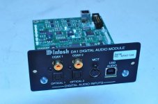
I thought it might be interesting to do a comparison between two Minidisc recorders, the MDS-JE480 which was one of the last models that Sony produced, a model that was firmly in the 'budget' category. The other is an MDS-JB920 which is an older model but much more of a heavyweight and dare I say more audiophile oriented. The budget MDS-JE480 does however sport one of the last (and best) developments of the ATRAC compression system 'ATRAC3 DSDP Type S' while the MDS JB-920 uses an earlier version of ATRAC. The later ATRAC versions were needed for the inclusion of LP2 and LP4 recording modes which doubled and quadrupled recording time available per disc, a very useful feature and one the MDS-JB920 lacks.

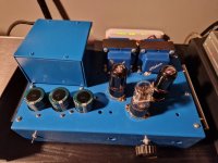
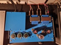
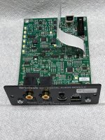
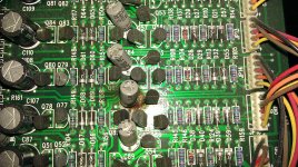
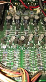
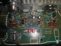
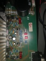
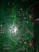
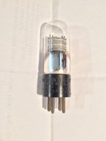
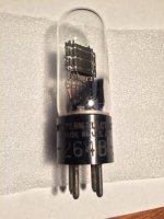
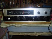
The actual MDS-JB920 used here is one I was fortunate to obtain a few months back. It has that classic early generation quality feel to it, it's a real heavyweight and offers very high build quality throughout. Unlike the MDS-JE480 which majors on using SMD components, this one uses mostly normal sized through hole parts.

https://www.diyaudio.com/community/...ttle-conundrum-at-the-end-of-the-post.405949/

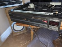
The MDS-JE480 I have owned from new and this picture is from the web. It is much more a lightweight budget model but it is nicely finished and very feature rich and of course having that very desirable ATRAC3 Type S encoding system.

Screenshot 2024-03-05 195712.png


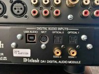
The recordings were made as follows. A Micromega Stage 2 CD player was used as the source and this was fed optically (TOSLINK) into both players for recording. The normal analogue output of each player was then captured and recorded for the comparison. For completeness another set of files was made using the analogue inputs on the recorders which adds the recorders own A/D convertor into the chain.

(for those familiar with the Micromega it has as only a coax digital output as standard but I modified this player years ago to add a TOSLINK output as well)

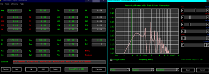
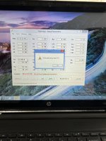
The recordings were captured using Audacity on a Dell Mobile Precision Workstation and the levels have been equalised. The raw files were converted to 320kbps MP3 to allow a reasonable file size which allows them to be attached to the forum.

I have labelled the players simply as 'Player A' and 'Player B' so you do not know which is which, however to avoid possible confusion Player A in one folder is the same as Player A in the other.

There are three zipped folders attached.

The folder called 'Digital' contains the two files recorded using the TOSLINK input, one for the MDS-JE480 and one for the MDS-JB920.

The folder called 'Analogue' contains the same two recordings but these were made using the analogue inputs to the recorders and so have the recorders own A/D conversion in the chain.

The third folder called 'Micromega' contains the same test track but this is directly recorded/sampled into Audacity with no recorder in the chain. So this can be thought of as a 'reference' and was taken from the RCA outputs of the Micromega. The Micromega Stage 2 uses dual Bitstream DAC's and had a very high reputation for sound quality back in the day.

(for anyone keen eyed I have double checked the files because you will notice a difference in compressed file sizes between players A and B in each folder and how they seemingly switch positions between the two folders. Why that happens I have no idea but it comes out that way when I repeated the process as a check. The uncompressed sizes are identical between all five files)

Attachments

Bose 901 upgrade

Bose 901 upgrade

Working all my life in hi fi and professional audio a few years ago I wondered what would happen if I replaced the internal wiring of a pair of 901’s for far better-quality wires. So, I bought myself a set of Bose 901 series 3 with the original equalizer. I allready had good results listening to 16 awg multi stranded silver plated speakercable; van den Hull snowline. So, I removed all the wire wrap cables and soldered the new cable from driver to driver. Use a 75-watt soldering iron minimum since the silver-plated cable draws a lot of heat away. And don’t be afraid to drill an extra hole to route the new wire from one chamber tot the other. Finally, I replaced the speaker connections for gold plated 4 mm female banana jacks.

I also upgraded the equalizer. In the signal path there are 3 10uf electrolytic capacitors in each channel. I replaced them for 10uf MKP. And also replaced all the transistors for new ones.

I can say that the difference in sound reproduction is very big; or to say it better; dramatic. The low end and high end is much better. The dynamic range is much better. The date code on the drivers is 1979; it is unbelievable what these 901’s can do! I am using a 100 watt amplifier and I am listening to high res audio via Qobuz. And I am using a USB to USB audio isolator to connect my PC to my DAC; I bought one via aliexpress for a few euro's.

I was searching online if somebody else had done this before, but I did not find anything sofar. So, I am very curious for anybody who will also perform this upgrade and tell me what you hear!
  • Like
Reactions: zobsky

Methods for assessing vacuum in tubes

I was intrigued by the sound differences between ECC83 tubes of different manufactures, even though on the cathometer they looked about the same, that is why I propose an indirect determination of the vacuum quality in the tubes by measuring anode current at a very low voltage. Worn tubes or with air in them give current values a hundred times higher than normal and smaller differences occur in tubes with different manufacturers, what do you think?

Attachments

  • 20240324_110322.jpg
    20240324_110322.jpg
    321 KB · Views: 68
  • Like
Reactions: tubelectron
Projects by fanatics, for fanatics
Get answers and advice for everyone wanting to learn the art of audio.
Join the Community
507,659
Members
7,883,003
Messages

Filter

Forum Statistics

Threads
405,972
Messages
7,883,003
Members
507,659
Latest member
jallerton