Carver Amazings crossover help!

Hello,

I recently picked up a pair of Carver Amazings. They are in good shape with no ribbon buzzing. They have always been on my bucket list and really do sound amazing IMO. There are a few issues I want to address, one being to build a more robust crossover. I’m using two AB International 600As bridged, one of each one producting around 1k each. At high power levels the crossover gets quite hot and doesn’t smell good, LOL. I’m wanting to keep the xover values the same, but just able to handle more power and dissipate more heat.

My issue is in the factory service manual the value for L2 in the schematic is 25uH but in the parts list it’s 50uH. The component itself has no markings on it.

Does anyone here have any insight on the correct value?

Any help or insight would be greatly appreciated

Attachments

  • 971737CF-DEAA-4093-B198-BF626E5400BC.jpeg
    971737CF-DEAA-4093-B198-BF626E5400BC.jpeg
    464.8 KB · Views: 206
  • 9609F7E5-105A-4A75-AE5D-4E68A32C8D7B.jpeg
    9609F7E5-105A-4A75-AE5D-4E68A32C8D7B.jpeg
    215.8 KB · Views: 256

Harman/Kardon HK3470 noise on the output entering the speakers

Since i'm new to the forum Hello to everybody:wave2: !
I have an old Harman/Kardon hk3470 with a 100Hz noise (yes i live in Europe) on the output with no music, just the speakers attached when it's daytime. When it's night time I don't hear it as much. I don't know what's causing it, but i'm sure after 20 years it should be recapped on the input stage at least. Also there is a 36mVDC at the left and a 6.2mVDC at the right channel, on the output when measuring (no load) with a multimeter (Voltcraft). Should i buy a new amplifier or can this be repaired somehow? When I bought it second hand 6 years ago, i had to do a little work on it since it didn't want to stay on, it constantly switched off. The problem was with a small capacitor hanging off the PCB, i also attached a bigger heat sink to one of the voltage regulators because it was burnin' hot, and also burned the PCB a little over the years. The weakest point i think is the transformer, because it becomes hot to the touch(>60℃ or 140℉) when it's on. Also here is the service manual attached if you wanted to look at it.

Attachments

Will it 'flap' - subwoofer vs woofer Mmd

Hi there,

I realise this is a pretty basic question, but I'm not sure about it..

If the strength of the motor is the same (somewhat hypothetical of course), is it mainly the extra Mmd that stops a subwoofer driver from 'flapping', when used in a subwoofer system?
I'm considering trying to use the FaitalPro 12FX600 in a vented subwoofer box. It appears to straddle between a woofer and a subwoofer in its design. They have provided a frequency response curve with a 45 degree off-axis plot, which makes me think it's intended as a woofer, but then they do this even with their 18" subwoofers.

Obviously from experience I know that if you try to put too much bass through a woofer (presumably with a lower Mmd) they do start to flap eventually.

Perhaps the surround has an influence as well?

TIA

For Sale Sjostrom Audio QSXM3 Extreme RIAA Phono Preamp Boards by Per-Anders

I have 2 brand new Sjostrom Audio QSXM3 Extreme Phono Preamp pcb boards available by Per-Anders. The design uses LT1028 (LT1115) along with an LT1010 buffer. An AD745 can be used in lieu of the LT1028 with some required cap and resistor value changes. MC & MM cartridge capable. These are bare boards and do not include any other parts or components. $75 each plus shipping. PayPal ok with added transaction fee. USA sale only.

PM me if interested.

Attachments

  • IMG_3418.JPG
    IMG_3418.JPG
    401.1 KB · Views: 148
  • IMG_3419.JPG
    IMG_3419.JPG
    313.1 KB · Views: 148

Headphone jack output TO Bluetooth headphones.

Help. I'm new at a church as the sound guy, and they have an amazing sound system that is run by a tablet. The amplifier is actually on the stage with no cable runs back to where the soundboard is. I would like to use wireless headphones to be able to solo each microphone, but because there are no wires to send the audio signal from the headphone jack / control room jack back to where we sit to run everything, I have no way to hook the headphones up. I need a Bluetooth amplifier that will plug into the quarter inch jack and broadcast to headphones. Does anybody know of such a thing. All I can find are Bluetooth receivers to plug into microphone inputs. Thanks.

JamHub MT16 Tracker mods

I hope this is a permitted post...

Is anyone interested in working on or expanding the capabilities of a 16 channel recording unit or just likes to tinker? I have some files for the PCB and some schematics and a build environment for the firmware. The owner of JamHub has asked me to open source the unit and will ship units to people interested in working on it (he has about 1500 of them that he does not want to put in a fill site). I believe if you are going to work on it, you can get them for free.

ixd704 (Ian Douglas) * GitHub has a number of files and descriptions of what I have done so far. I also have a working firmware image of 3.0.2 that can be installed to upgrade any of them that are running older fw versions. They all come with the telnet port active and the root password is in the Github description.

It would be fun to be able to remote control it via WiFi (it has an AP). Not sure what kind of work would be required to get it to transmit the channel data over USB to a computer system. The code for the menu control buttons is available and the processor appears to be able to do far more than it currently does.

Currently trying to make a port splitter so that the Tracker does not use up the remote port on the JamHub reducing the number of headphone remote mixers that can be used with it plugged in.

If you are interested, take a look at the github site. There is contact information on the site to get a tracker for experimenting with.

Ian

What is wrong with this HT room?

Hello,

Here is my HT room layout, I can’t seem to figure out how is bass not heard from my front speakers. in a different room my 12 inch bass drivers seem to be producing a lot of bass but in this layout I am unable to figure out what is the real issue? Here are few things:

1. The room is untreated and walls are made of cement blocks.

2. Speaker polarity is fine. Even if I play either of them individually, FR seem to have a little bass than FL.

Can anyone please help by pointing out what is the real issue in this room? and How can it be resolved?

Thank you
e399dd15-983f-4084-8de5-ff7fb89b7847.jpeg

Adcom GFA-5800 wattage question

I am going to apologize upfront if this is a super simple question, so please bare with me.

What I am looking to do is a bias check/adjustment (in necessary). According to the service manual, below is the first step of the procedure.

"With amplifier connected to 8 ohm resistive load, apply a 1khz sine wave at the input to achieve 83.3 watts at the output."

So my question is, is there a formula for finding out what values I would need to calculate to find the wattage value?

I know the voltage will be between 115-120, but I do not know what my current would be or where I would check for it. I have attached the pdf if anyone is interested and sorry for the crazy question.

Side question, anyone know a decent 8 ohm resistive load that does not break the bank or do a lot of folks here make their own.

Thanks.

Attachments

Scourge, Bulwark, Marauder, Dreadnought "front end" cards for DIY VFET amp

It was a delight and an honor when Nelson Pass asked me if I would like to design some additional front end cards for the DIY VFET single ended amps, rather like the additional front end cards I designed for the diyAudio First Watt M2x amp. Naturally I told Nelson "Yes!!" and started work right away.

Today I'm unveiling the first four such cards, named Scourge, Bulwark, Marauder, and Dreadnought. Attached below are four .zip archives, one for each card. The .zip archives contain
  • Full schematics in .pdf form
  • Detailed Parts Lists including Mouser part numbers, in .xls spreadsheet form
  • Web links to Mouser "one click" shopping carts for easier ordering
  • Gerber CAD files for PCB manufacturing. Send these to a fab and have some boards made!
Also attached are schematics as image files EXCEPT for Dreadnought, which I will attach to post #2. Dreadnought's schematics extend over three pages (!) which exceeds the diyAudio Forum limit for number of attachments per post.
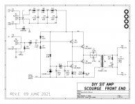


SCOURGE CIRCUIT

Scourge is a unity gain follower driving the primary of an Edcor transformer. It is similar to the front end card which Nelson is providing, except that it uses Fairchild components instead of obsolete and out of production Toshiba parts.
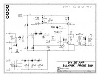
BULWARK CIRCUIT

Bulwark takes the basic circuit design of a preamp that Nelson Pass designed in the middle 1970s, and applies two modifications: (1) instead of a single ended input stage plus an opamp DC servo, Bulwark uses a differential input stage and no DC servo. (2) Bulwark flips the circuit upside down: what was NPN is now PNP and vice versa.

Bulwark uses the same cute bootstrap circuit (Q6 + R18) to raise the effective AC collector load on Q4, to extremely high impedance levels. This means that Q4 has extremely high gain. And since Q6 is an emitter follower, the output impedance which drives the transformer primary, is quite low.

R22, R21, and C10 allow for future modifications if the builder so desires. Besides the 5X gain provided by the Edcor transformer, suitable values of R22 and R21 can be installed to increase the gain further. If desired.
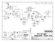
MARAUDER CIRCUIT

Unlike the Nelson Pass front end, unlike Scourge, unlike Bulwark: Marauder has no Edcor transformer. It produces a very large output signal swing by having a DC-to-DC converter circuit that creates a high voltage supply on-card, significantly higher than the 36V provided by the amplifier's SMPS. The high voltage supply is called "POS_BOOSTED" on the Marauder schematic, and is applied to a high voltage opamp, the OPA552 from Burr Brown. This opamp operates at a gain of ((R15+R14) / R14) which equals 6.1 times. A wee ooch higher than the gain of an Edcor transformer.

Front end cards with a transformer output, can produce either inverted polarity or non-inverted polarity through the simple expedient of swapping the secondary output terminals. But Marauder has no transformer, so it includes a pair of unity gain opamps (+1.00X and -1.00X) and a switch, to provide the polarity swapping option. The switch lights up a red LED (D6) on the board if inverted polarity is selected, and it lights up a green LED (D5) on the board if non-inverted polarity is selected.

I will let Nelson Pass explain why and when this polarity swapping option is useful.

DREADNOUGHT CIRCUIT (schematics attached to post #2)

Dreadnought, like Marauder, has no transformer. So it has a DC to DC converter "JBOOST1D" to create its own high voltage supply "POS_BOOSTED". Dreadnought also has a pair of unity gain opamps and a switch, to provide either inverted or non-inverted polarity, whichever the user desires.

The main amplifier in Dreadnought, running off the POS_BOOSTED high voltage supply, is an all-BJT, discrete transistor, transconductance amplifier. Differential amplifier Q1+Q5 drives current mirror Q2+Q4 to provide a single ended output at the base of emitter follower Q6. Then Q6 drives a common emitter output stage (!) called Q8, with constant current load Q7. The super high impedance (transconductance) output from Dreadnought, drives the power amplifier PCB, which in this case is the gate of a VFET.

Diode D11 is an antisaturation clamp and resistor R43 is a current limiter for negative clipping events. With a supply booster it turns out to be important to prevent high current pathways, else you may latch up the booster.

Gain is ((R12+R11) / R11) = 6.1 times. A tad bit more than an Edcor transformer provides.

EXTERNAL BACKUP SITE FOR FRONT END CARD DESIGN & MFG DATA

I have stored these four .zip archive files on my personal website as a back-up in case diyAudio temporarily goes offline or becomes unbearably slow. Links to these files are below. Please don't complain about the lack of html beauty or modern ease of use; be amazed that the backups exist at all.

Scourge zip archive

Bulwark zip archive

Marauder zip archive

Dreadnought zip archive

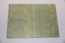
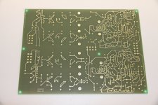
PHOTOS OF THE FOUR BOARDS: attached to post #18 of this thread


_

Attachments

  • Like
Reactions: Sweetsweetback

DynaKitParts ST-35 power supply mods?

Hi all, I'm considering building a new DynaKitParts.com ST-35, and I am wondering about the power supply. I am not interested in the Enhanced Fixed Bias board for the ST-35 and have ruled that out for reasons that I need not go into here.

1) DynakitParts.com does offer an optional choke as shown in the bottom half of the ST-35 schematic below. How and why is the choke an improvement?

2) Other capacitors are available online to increase the power supply capacitance by as much as double. Is it worth the trouble, and if so, which values (A, B, or C) are most important because triple and quad caps are available in all sorts of values and combinations, some of which can be combined to increase only A, or A and B, or all three. For example, I have found 80/70/20 and 120/40/20 and 100/47/22. It also is possible to use two caps to get 120/80/40 - there is room on the tiny chassis for two caps believe it or not - however, a second cap would prohibit the use of the choke since there isn't room for both.


1681270403798.png

Questions on Eminence Alpha 8a midbass box for indoor listening levels

Hello everyone,

I recently built a horn which I'd like to cross over to at 700Hz, based on recommendations.

I have two pairs of Eminence Alpha 8as, and planned to build a box that matches the vented enclosure spec Eminence suggest.

However, having 4 drivers makes me wonder if:

  1. Do I need 4 for indoor listening?
  2. How would I account for 2 drivers per box when the original vented design is for one driver?
Thanks for your thoughts!

MP3 player/bluetooth board damaged after connecting to amplifier

Hi everyone,

I am new to this platform and trying to resolve one of my expensive problem.

I lost Left channel output of my Bluetooth board while once connected to my amplifier, again my MP3 player one channel weaken after connecting to the same amp.

can any one provide me a solution to this problem by sharing a circuit diagram which can be used between pre-amp and Bluetooth/MP3 player.

Some kind of reverse blocking circuit, i tried some resistance at input stage but the gain is disturbed.

Please guide,
thanks in advance

Teac A-4070 reel to reel hot chassis (bad transformer?)

I bought this Teac A-4070 reel to reel a few months ago for almost nothing and have been trying to refurbish it just for fun (I was a CET in the 70s but am rusty at troubleshooting at times)
When I first noticed the hot chassis I moved wires around from the transformer and fixed a few dodgy connections and it went away, Now the hot chassis is back.

Of course the chassis is not grounded and has a non-polarized 2 prong power cord (1971).

From the chassis to the house earth (ground on the 3 prong socket) I get 89 to 92 VAC. From chassis to the 0V transformer tap I get 89 to 92VAC.

I replaced all of the electrolytic capacitors as they were off spec by 80% to over 100%, the hot chassis did not start after that work.

If you look at the attached schematic I put readings (In Red) from the transformer taps to the chassis.

I replaced the bridge rectifier even though it tested good because the voltage to chassis on that tap was so low compared to the others.

Now I pulled the transformer and tried some inductance readings on the secondary (with a cheap component tester) hoping that leakage would show up.
Results:
With the primary shorted:
40V tap to 0V tap = 0.39mH
50V tap to 0V tap = 0.56mH
60V tap to 0V tap = 0.73mH
80V tap to 0Vtap = 1.02mH
With the primary open I got 3.6mH on all taps to 0V tap.

What do you guys think?


Trans VAC 5-27-23.jpg

Some one can help me to fix active crossover

Hello some one help me active crossover
Calculator.
My 3way active speaker frequency point 320 &3200 Hz and currently using DBX 3way active network filter ,so I would like to update fix resistor value instead of trim potentiometer . So can I remove potentiometer and replace right resistor value ?
Thanks for key in

Attachments

  • IMG_1065.jpeg
    IMG_1065.jpeg
    509.6 KB · Views: 97
  • IMG_1066.jpeg
    IMG_1066.jpeg
    516.1 KB · Views: 100

Need help designing MOSFET / JFET class A amplifier

Hi all,

This is just a concept that I had dreamed of when I was looking at the Pass ACA class A amplifier schematics.

It uses IRFP240 MOSFET in common-source operation to amplify voltage and current.

amp_camp_s1.PNG

Now, there is a second IRFP240 that is used as constant current source.

amp_camp_s2.PNG

What I was wondering is what if we add a long tailed pair JFETs to be able to accept balanced inputs (XLRs for example)?

I am not experienced that much in transistor circuitry, but I have come up with draft design in TINA-TI simulator. It uses common components and I feel like it is almost complete, but looking for input from other people.

Typical balanced signal is 4Vrms, so I figured the voltage gain should not be that much - 2 or 3 will do. But the current gain is what I am having hard time understanding.
I am thinking worst case scenario is 2 ohm load and with gain of 2 we get 8Vrms so that is 4 Amps. With 4 ohms speaker, it is 2 Amps. Is IRFP240 even capable of such output?
Supply voltage is also not determined...

Attached is simulation file.

sch.PNG

Attachments

Marantz 1050 phono stage

13 / 5.000

Resultados de traducción​

Resultado de traducción​

Hello everyone. I have a Marantz 1050. This unit has two 2SA1039 and four 2SC2390 on the phono stage. My intention is to replace the originals with KSA992 (for 2SA1039) and KSC1845 (for 2SC2390). Are they both good substitutes? Thank you.

Attachments

  • Marantz 1050 phono stage diagram.jpg
    Marantz 1050 phono stage diagram.jpg
    216.9 KB · Views: 375

FRD & ZMA files for SB Acoustics SATORI TW29RN-B-8 / SATORI MR13P-8 / SB34NRXL75-8

Hello everyone,
I'm asking for your help so I can start working on the crossover part.
I have the following speakers:
  • SB Acoustics SATORI TW29RN-B-8;
  • SB Acoustics SATORI MR13P-8;
  • SB Acoustics SB34NRXL75-8.
I tried to use FPGraphTracer and managed to extract FRD and ZMA files only on SATORI TW29RN-8. For the others, I cannot use the graph from the datasheet on the manufacturer's website, because it is of poor quality and FPGraphTracer cannot extract the files.
So, please, those of you who own the FRD and ZMA files, can you share them with me? Please!

Thank you!

Attachments

  • IMG_E3984.JPG
    IMG_E3984.JPG
    777 KB · Views: 269
  • IMG_E3985.JPG
    IMG_E3985.JPG
    679.7 KB · Views: 256
  • IMG_E3986.JPG
    IMG_E3986.JPG
    368.3 KB · Views: 196
  • IMG_E3987.JPG
    IMG_E3987.JPG
    571.8 KB · Views: 252

Modding old PA speakers. Fender 115XP…replace dual piezo with Fostex horn tweeter?

I found a pair of Fender 115XP speakers, w/ 15” Eminence woofers and a Motolora dual piezo horn, for almost nothing. Used them for an outdoor party with no problems.
However, to me the highs are grating and aggressive, even out on the dance floor, and eq just dulled them. I can make crossovers, so I’m tinkering with a filter, but these are not the supposedly higher quality Powerline models.
I also have a pair of old Fostex horns I could swap in, with a filter @2kHz. Would those be a better alternative? What‘s the CW on piezos vs. conventional dynamic horns for loudness plus sound quality.
9445B221-B46F-4296-A0EF-95465F438CA7.jpeg
446FB409-C9D2-4174-AA72-A80E7898DED2.jpeg

X-Tronics soldering station

I have an X-Tronics Model #4010 soldering station. The actual iron itself has just failed AGAIN, for the THIRD time, in the exact same way----the plastic retaining housing around the sheath holding the heater assembly has crumbled, making the iron useless. Anybody else have this problem? I have several spare heating elements and tips, but with the broken housing, the iron won't work. Having this same failure THREE times makes me think of getting another complete station, instead of replacing the iron AGAIN. Other than this failure, the iron has been pretty good for my hobbyist usage. They're about $90 new, and the replacement irons are about $25. Suggestions for a replacement? I wish I could just find a new housing part, but they don't sell that separately. It's definitely the Achilles heel of this brand.

TPA3110 design issues

Edit: The issue is solved by replacing R7 with 10ohms

Hi there, I am currently designing a class D amplifier board. My ordered PCB has finally arrived, it took me a while to solder the rest of the tht components. After connecting the audio source and the speakers, no sound is produced.

The schematics of my design is attached to this thread. The board features with TPA3110, which is the amp itself, two preamplifiers for left and right channels, and a DC 5V external output. The pre-amps and the external output both powered by 16V from a DC-DC boost converter.

I wonder if what's going on and what am I missing. It would be wonderful if you could help me~ Thanks.
SCH_Amp V1_2023-06-02_page-0001.jpg

Attachments

"A Rumination Upon Audio Research, VW's Phæton, and Subaru vs. SAAB"

FWIW & Your Mileage REALLY Might Vary, I have shared on [LINK:] Positive Feedback Online some of my thoughts about the Audio Research "Assignment for the Benefit of Creditors" situation. Back when I was a trial lawyer, I was one of three lead lawyers on a $67 million Involuntary Bankruptcy. And, I was involved in many much smaller cases.

The Marketing course I took was one of the best courses I ever took. To give the Overview from 30,000 feet, a very important distinction is between "Me" Marketing and "You" Marketing.

"Me" Marketing is something like:

"John Marks is an Industry Pioneer in high-bit-depth digital recording."

"You" Marketing is something like:

"JMR's high-bit-depth digital recordings guarantee you will enjoy Fatigue-Free Listening."

Two important points:

1) I do hope that ARC survives and prospers.

2) In view of the fact that the "GhostMeters(tm)" were announced in 2019, and the TWS Group acquired ARC in 2020, I assume that the most recent management team was saddled with a decision that some or all of them might not have agreed with.

Thanks to David Robinson for providing the soapbox.

ciao,

john

Might some here critique the power supply I want to buy

I’m unsure if the purpose of this forum is a little above my head. I consider what I do diy in the way that I don’t go to Best Buy and choose a big box store brand. I’m getting into using pre made components like amplifier boards, raw drivers and the like to create my audio equipment. I just wanted to preface the question with an attempt to show respect to the legit circuit builders.

I’m about to order this power supply

https://www.trcelectronics.com/View/Mean-Well/EPP-500-24.shtml

and be done fiddling with lower power amazon units. I’m currently using a 24v 6a open frame supply,

Zerone AC 100-240V to DC 24V 6-9A Switching Electricity Supply Module 150W High Power Industrial DC Electricity Supply Bare Board https://a.co/d/drK2azZ

which may be introducing noise into my Dayton Audio Kabd boards, or, maybe the boards may have an inherent low level noise. Either way I like the versatility of the kabd boards and have decided to move into a power supply that will be plenty for my needs with room to grow.

Is there any dissuasive feedback on the mean well 500w 20a unit? Maybe a lower cost route that is as good or better? The amp boards will be In close proximity to the power supply in this small 7”x6”x3” steel electronics enclosure. Is this arrangement too close because of noise issues? I’d be willing to switch to a similar enclosure that would allow maybe ~6” spacing between supply and boards if necessary. Thanks in advance, happy new year also.

F2E2CD9C-344F-4F05-83B6-71BE9A807A2E.jpeg

All Overture series chip amplifiers from TI complete list

With this post I wanted to create a quick reference to all chipamps from TI that are labeled Overture series.
I am assuming all of these should be able to achieve as low of THD figures as LM3886 (0.0033% @1kHz into 4ohm). THD+N probably will be worse since power output is lower.

Since LM3886 is out of stock I figured it would be interesting to use alternatives (even though they are not as powerful).

Overture chip amps list:

#1 LM3886
  • 68W into 4ohm, Vcc=Vee=28V
  • 50W into 8ohm, Vcc=Vee=35V

lm3886.png

#2 LM4780 dual channel
  • 55W into 4ohm, Vcc=Vee=25V
  • 60W into 8ohm, Vcc=Vee=35V

[equivalent schematics is missing from the datasheet]

#3 LM2876
  • 40W into 8ohm, Vcc=Vee=30V
  • NA into 4ohm

lm2876.png

#4 LM4766 dual channel
  • 40W into 8ohm, Vcc=Vee=30V
  • NA into 4ohm

lm4766.png

#5 LM1876 dual channel
  • 22W into 4ohm, Vcc=Vee=20V
  • 20W into 8ohm, Vcc=Vee=22V

lm1876.png


Any other chips I missed?

Pair of Zebrawood veneered wooden monoblock amp bases

Pair of wooden monoblock amp bases veneered in zebrawood. Craftsmanship of construction and veneer are both excellent. There are a couple minor cosmetic blemishes in the veneer (one appears to be some excess veneer glue, which I'd never noticed before), but they are in otherwise excellent shape.

Outer dimensions are 9 1/4" W x 11 1/4" L x 3 1/8" H. Dimensions of inset for top plate is 8" x 10", and 2mm deep. I believe that these were originally intended to be bases for Bottlehead Paramour amps, but I can't say for certain as I am not the original builder and have never owned a Bottlehead amp.

Asking $100 + actual shipping.


D73BE3B6-D27B-406F-AF14-45C0365A2340.jpeg
67537AB4-EF3A-48B5-A063-EABC668BA9F1.jpeg
E88295B3-4D5E-46FB-BC3F-CD6F63DE40E0.jpeg
6BD0F8E9-9ED5-41F2-94F2-AFBCD30FF93B.jpeg
BEDF782B-A3A1-4848-9D52-4D3B3212283F.jpeg
AF338E66-D9F2-459D-AD15-F485ADB576C7.jpeg
A47C7BA5-67EC-4CF8-B10E-06A75E34CAEC.jpeg
296624A7-94A0-4C8D-8A5D-286E749F3A21.jpeg
D84D711E-389D-4B4D-B2CF-A17F5CCB661A.jpeg
CB957826-D943-40EE-AC3B-06A7EFBE9C8D.jpeg
72197015-AFAE-4BBA-BAB4-E33224DFAEB8.jpeg
9865811F-62DB-4854-B1DE-3E8AC87269E3.jpeg
1631BFCD-F38D-49AF-9F67-6C0850FA918F.jpeg
A7448716-57CA-4427-A31F-46D933E6FA3E.jpeg
C06C5E7B-2078-4D2A-84FC-64CA31172851.jpeg

Safety of Use Question or Repair Tip - Denon AVR-S700W

Hi!

Can anyone offer if the situation described below is safe for use, the repair needed, or steps to provide the information required to make that determination?

I received a Denon AVR-S700W with a faulty HDMI output from a lighting strike.
I have been using the amp function without any obvious issue.
I apparently overheated it with a new speaker (2.5" & 12" drivers) and it went into protection mode, clicking and showing red/green on the power LED.

After it cooled down, it still clicked, but the red light wasn't coming until I pressed the button.
So I opened it up to look for any obvious burnt components/leaking capacitors and identify the clicking presumably relay at the lower end of the power in board closest to the rear of the unit.
I haven't found schematics or the service manual yet, but will keep looking.
Relay_1.jpeg
Relay_2.jpeg


I planned on using a wood stick to lightly touch the suspected relay (outlined in red) to verify.
Touching it caused it to stop clicking and the AVR booted up normally.

I have been using it as a spare amp for my introduction to speaker experiments, so once I figured out how to get to pure direct and out of set-up mode I have not been too bothered by the lack of HMDI.

TDA8954TH - XH-M252 board - anyone?

Anyone tried this amp board?
TDA8954TH Class D High Power Dual-Channel Digital Audio Amplifier Board 420 I1A2 192948093630 | eBay
I think to purchase one and to try to convert it to 4 SE channels to make active speakers with a DSP.
And maybe one cheaper mono board with the same TDA8954 IC for subwoofer.
How it sounds for full range speakers?
The default sampling frequency is 350kHz, but it can be set up to 500kHz, according the datasheet.

A friendly hello from the depths of the Teutoburger Forest...

Hello to all forum members. I'm Jürgen, I come from a village in the Teutoburg Forest in Germany and have been fascinated by good hi-fi systems for about 40 years. I once trained as a radio and television electrician, then retrained on IT systems, but had to retire early. In all the years I have repaired and restored mountains of hi-fi devices and have always done the same work that I have now "forgotten almost everything" that you might need to build a fine device yourself. So I'll hang around here a bit as a professional dilettante in the forum and hope that I can refresh my almost 60-year-old brain again.
Well then, have a nice evening everyone and bye until then...

QUAD 240 Series - does the Sonic Character correspond more to that of the Quad 405 or the 303 ?

From this amp under
https://www.hifiengine.com/manual_library/quad/240.shtml
I haven't heard before.
A friend of me found an offer of this model for 500 €
Maybe one of the members know, how this model sounds - thank you very much.

P.S.: Schematic is to find in the user manual.

Attachments

  • quad-240_001[1746].jpg
    quad-240_001[1746].jpg
    58.4 KB · Views: 176
  • quad-240_002[1747].jpg
    quad-240_002[1747].jpg
    70.3 KB · Views: 154
  • f472ec9f-f3be-4d94-a824-31ed48a725e2.jpg
    f472ec9f-f3be-4d94-a824-31ed48a725e2.jpg
    130 KB · Views: 133
  • 0aa513aa-346e-47b0-b6c6-12e4a65d62e3.jpg
    0aa513aa-346e-47b0-b6c6-12e4a65d62e3.jpg
    96.1 KB · Views: 140
  • 6c0e25f3-3ae9-401e-b4f9-496bc2c49a6c.jpg
    6c0e25f3-3ae9-401e-b4f9-496bc2c49a6c.jpg
    80.7 KB · Views: 140
  • 22eebc95-d71d-4334-b2c8-29536edd38ee.jpg
    22eebc95-d71d-4334-b2c8-29536edd38ee.jpg
    137.6 KB · Views: 174
  • quad-240_005[1750].jpg
    quad-240_005[1750].jpg
    204.3 KB · Views: 184
  • quad-240_006[1751].jpg
    quad-240_006[1751].jpg
    163.6 KB · Views: 141
  • quad-240_004[1749].jpg
    quad-240_004[1749].jpg
    134.7 KB · Views: 144
  • quad-240_003[1748].jpg
    quad-240_003[1748].jpg
    156.9 KB · Views: 177
  • Quad-240-User-Manual-plus-schematic.pdf
    Quad-240-User-Manual-plus-schematic.pdf
    2.2 MB · Views: 151
  • quad_240s_datasheet[3598].pdf
    quad_240s_datasheet[3598].pdf
    1.9 MB · Views: 114

VACUUM TUBES -- (2) 6C6 (2) 6A6, (4) 25Z5, 84/6Z4, (2) 1626 National Union US Navy RCA -- NH USA

best offer
Might be new or used
I don't know
UNTESTED

VACUUM TUBES -- (2) 6C6 (2) 6A6, (4) 25Z5, 84/6Z4, (2) 1626 National Union US Navy RCA -- NH USA

Attachments

  • 20221028_120637.jpg
    20221028_120637.jpg
    540.5 KB · Views: 95
  • 20221028_120641.jpg
    20221028_120641.jpg
    654.2 KB · Views: 89
  • 20221028_120646.jpg
    20221028_120646.jpg
    672.2 KB · Views: 109
  • 20221028_120648.jpg
    20221028_120648.jpg
    808.6 KB · Views: 94
  • 20221028_120705.jpg
    20221028_120705.jpg
    724.7 KB · Views: 85
  • 20221028_120716.jpg
    20221028_120716.jpg
    666.7 KB · Views: 90
  • 20221028_120721.jpg
    20221028_120721.jpg
    647.9 KB · Views: 86
  • 20221027_092503.jpg
    20221027_092503.jpg
    899 KB · Views: 86
  • 20221027_092507.jpg
    20221027_092507.jpg
    883.1 KB · Views: 82
  • 20221027_092519.jpg
    20221027_092519.jpg
    762.8 KB · Views: 82
  • 20221027_092534.jpg
    20221027_092534.jpg
    823.8 KB · Views: 89
  • 20221027_092539.jpg
    20221027_092539.jpg
    765.4 KB · Views: 98
  • 20221027_092542.jpg
    20221027_092542.jpg
    859.5 KB · Views: 87
  • 20221027_100333.jpg
    20221027_100333.jpg
    868.1 KB · Views: 76
  • 20221027_100338.jpg
    20221027_100338.jpg
    899.9 KB · Views: 92
  • 20221027_100347.jpg
    20221027_100347.jpg
    844.5 KB · Views: 90
  • 20221027_100351.jpg
    20221027_100351.jpg
    864.8 KB · Views: 91
  • 20221027_100609.jpg
    20221027_100609.jpg
    825.4 KB · Views: 94
  • 20221027_100616.jpg
    20221027_100616.jpg
    841.3 KB · Views: 85
  • 20221027_100627.jpg
    20221027_100627.jpg
    840 KB · Views: 103

Connecting powered powered subwoofer to dual mono amp

Integrated amplifier is dual mono with left and right pre-outs. When connecting an RCA (L & R) from integrated pre-out to subwoofers Left and right inputs, both speaker makes a sound even if the balance is all the way to the right, reverse is true if the balance is all the way to the left. Removing the RCA cable from pre-out to sub removes the problem. Would it help if I only connected the "+" from left and right and connect only a single "-"?

HELP! Precision Devices 2450 - ROAR, TH, Bandpass or something else?

Hi!

I have a pair of Precision Devices 2450, 24" speakers, which I´d like to build something else for than regular ported boxes. I have read quite a lot and experimented in hornresponse, but feel that I don't have enough experience too decide if i'm on the right track. I don't want to bulid something that doesn´t work.
On PD:s site they say that they should work in horns, but apparantly the BL isn't sufficient for example paraflex.
I´m curious about ROAR, Tapped Horn or 8th order bandpass solutions, but need some help to decide what would work. For ROAR and TH I have had some success getting a reasonable response curve, but 8th order bandpass is just a mess. I know there are a lot a very skilled builders here who propably could make it so much better.

Some things like phase response and group delay I don't have a clue how it works and would appreciate some info about that too.
If someone is interrested in helping me design boxes, I would like them to be no bigger than 185x80x90 Height, Widht, Depth, so I can get them through doors.
I'm attaching some pictures from boxplan and hornrespons so you can give me feedback.

The other part of the system will consist of 8 pcs 10", 4 pcs of 6,5 and a pair of horn tweeters. The PD 2450:s will have a Yamaha P7000s each, the 10":s a QSC PLX3402 and the 6,5 and tweeters a Pioneer SX1250. The equalisation and filtration is done by a Driverack PA2, except for the crossover between the 6,5:s and the tweeters.

I would appreciate any help I could get.

Attachments

  • Boxplan ROAR.png
    Boxplan ROAR.png
    21.6 KB · Views: 119
  • Hornresp 01_1 Roar.png
    Hornresp 01_1 Roar.png
    6.2 KB · Views: 128
  • Hornresp 01_2 Roar.png
    Hornresp 01_2 Roar.png
    6.6 KB · Views: 139
  • Hornresp 01_3 Roar.png
    Hornresp 01_3 Roar.png
    6.1 KB · Views: 128

Threshold SA/1 and FET Eleven/g

Just finished recapping my SA/1's with four CDE DCMC104M100DF2B 100,000uF, 100V from Digikey per chassis to replace the 39 year old Mallory's 29,000uF 80V.
They still have an inventory of those so all Threshold SA/1 - SA/2 - SA/3, S/200, S/300, S/500 and S/1000 owners can order fresh ones.
These were even lower in height than the old ones but fitted perfectly in the 3" clamps and the groundplate drilled holes.
Would the 100,000uF per can be a problem?

Although they were manufactured/shipped from the CDE factory this year to Digikey I still softstarted them within three hours from zero to 220 volts with a variac. I start the Thresholds always with a variac (but than in a few seconds ;-)) for minimal stress especially for the on/off Airpax circuitbreaker.
Threshild SA1 recap.jpeg


The FET Eleven/g (a FET TEN 'e' series for the German market) has two Sprague Series 53D 35V 15,000uf axials and replacement for those is hard.
The best I could find were Vishay/Sprague 25V 18,000uF axials. Over the old ones I measured 23 Volts DC with 230 Volts AC.
Would that be a problem?
IMG_3137.JPG

LM3886 super gainclone gets simulated in TINA-TI

Just for fun exercise here decided to run the schematics in the simulator.

Original Cordell's schematics is attached:
sgc_from_book.jpg

Here is the TI application note schematics for the servo:
inv-sch.PNG

And here is my take on it - drafted in TINA TI simulator:
sch-sim.PNG

It is almost the exact copy of the one from the TI application note. Super gain clone has its phase reversed back and so the LM3886 outputs the signal with the same phase it was fed to the input of the first opamp. I did not bother with that additional step in my schematics. It allowed to save on one additional opamp. I am using OPA2134 as I personally listened to it and I like the sound a lot. It also has ah-ok DC precision to work as a servo. Loading OPA2134 with easier load (2K in my case) should produce less distortion - according to the graph in the datasheet.

Servo values got adjusted to give difference of 47dB at 20Hz - that is between usable signal and the feedback one:
freq.PNG

Frequency response is -0.03 dB at 20Hz and -0.11 dB at 20KHz. That is with the gain of 20dB:
freq-resp.PNG

Stability components were added to the schematics to insure proper performance of the LM3886. As far as I understand opamp stability theory - idea is to make sure we are avoiding oscillation condition where the output signal phase is inverted 180 degrees and fed back to the inverting input of the LM3886. With given values for stability components phase is preserved under 180 degrees shift up to 934 KHz and depicted in the graph below:
phase.PNG

Comparing that result to the open loop gain graph for LM3886:

lm3886-bw.png

At the end I just wanted to mention that I am not an expert in the field and could have made mistakes - therefore I would really appreciate any input on any part of this analysis.

Attached is the zip file with simulation.

Attachments

  • Like
Reactions: dreamth

RCA line level switcher to allow dedicated two channel stereo and multichannel surround

My audio system has always been multichannel surround built around a digital home theater processor. What I'd like to do is isolate two channel sources from multichannel sources and run two channel stereo CD player/DAC and turntable/Pearl 2 phono pre through the Iron Pre I'll be building and leave all the multichannel audio (TV, bluray, roku, etc) to the current surround processor while utilizing the same amps and speakers at all times.

A line level switcher would allow this, but currently my passive sub is driven by the processor as I'm utilizing all the xover and eq controls there so that complicates things. I could ignore the sub controls on the processor entirely and instead run the sub via MiniDSP for instance but I'd like to avoid that.

Surely I'm not the first nut to do this without wanting to unplug/plug RCA cables each time. What solutions have others created?

For reference current front end is B&K Reference 50 S2 driving dual mono PassDIY F6 for left and right speakers, a monoblock F6 for center channel speaker, a Crown XLS1002 for passive sub and a B&K AV2500 for surrounds. Main speakers are DIY Bordeaux, center is DIY Statements center, sub is DIY Dayton Ultimax 15.

What are the downsides to a Split-Bobbin construction for use in tube amp plate power supply?

I've been trying to find a definitive answer to the question but I can't seem to find anything directly relating to my intended use. The intended us is... .

  • I have a stereo, dual-mono constructed, 2-stage push-pull 2A3 power amp that requires a separate power transformer for its driver stage.
  • Each channel of push-pull 2A3s uses its own 500VCT 150mA power transformer. Those are on the chassis, ready for action.
  • Each channel will use a 6N6P LTP with its plates DC-coupled to the 2A3 grids. Each 6N6P triode will be drawing about 15mA, so I'll need 60mA for four triode.
  • I need a +150VDC plate supply for the 6N6P tubes which will be 'stacked' on top of the +325VDC plate supply for the 2A3s.
  • I already have the 6.3VCT 1.2A transformers necessary for the 6N6P heaters.

I don't have a lot of room on the chassis. It's an old project that I didn't lay out very well. Oh well, it is what it is.

I was thinking of using a pair of Triad Magnetics isolation transformers (117VAC:117VAC) and rectifying the 117V secondary with CRC filtering to bring the rectified voltage to +150VDC.

My choices are:

The VPS230-110 is a bit smaller, so I'd like to use that if possible. But it uses split bobbin construction. I understand that has the lowest capacitive coupling of the various transformer configurations, but does that come at the cost of a lot of uncontrolled electromagnetic radiation? I don't want to inject hummmmm into everything.

The N-48X is an unknown quantity, but I know Eli Duttman has used that series of transformers in some of his amp designs. Do single-bobbin EI core transformers control their electromagnetic radiation better than split bobbin transformers?

I understand toroid transformers have the tightest control over their radiation, but they also couple line noise to the secondary more readily, and they also have a bigger current surge at power on. I could go with a toroid if it's absolutely necessary, but they're all pretty large. The minimum diameter in a transformer with 120V secondary from Antek is 3,6" for a donut rated at 50VA (120V at 400mA). That's way more than I need.

What's better in this particular usage situation? Split bobbin? Or EI core? Or does it not matter?

Comparison of ACA v1.16 with v1.18

Just completed building an ACA v1.18 to go with my 2 plus year old ACA v1.16.

1. The ACA v1.18 does not make that sound heard through the speakers when you first turn it on, unlike the v1.16 which does.

2. The ACA v1.18 runs cooler than the v1.16 as a stand alone stereo amp.

3. But it runs much hotter then the v1.16 when used together in the Mono RCA Bridged configuration.

Can someone please tell me if these differences between the two amplifiers are typical, or not? If not, any suggestions on how to address?

Also, one of the v1.18 LEDs is slightly dimmer than the other.
Is this something I need to be concerned about?

Thank you for your consideration and any help you can offer.
Yours,
Michael

Questions on first speaker design - with downfire

Hello,

i am new to speaker design. I am inspiried by the Apple HomePod, where the woofer is facing down and the Homepod have 5 tweeters.
So my questions are
  1. is it possible to direct the woofer to the bottom? Does it affect the sound?
    1. Or it is only possible when the woofer plays only up to 800 Hz and the tweeter plays from this point. 800 Hz due to sound localisation. First research says that frequencys below 800 Hz cant be located by human ear. Is it right?
  2. is it possible to have more than one tweeter in one speaker?
    1. How do the tweeters affect on themself? (Interference?)

Qualiton APR204 6922 Preamp questions

My tube preamp (Audio Hungary Qualiton apr204) either wears fast the line stage tubes (6922) or all the 3 pairs i bought were defective (1 pair genalex gold lion, 1 pair electroharmonix and one NOS pair voskhod 6n23p) They lasted about 6 months with aprox. 2 hour per day listening. One day when i turn on the preamp, the 6922EH catastrophically failed with sparks and flashes inside the right channel tube and VERY LOUD noises heard from the speakers. The previous day before total failure i was hearing clicks, pops and squealing from the right channel. Fortunately my Power Amp and speakers survived.
I disassemble the unit and copy the line stage schematic from the pcb traces.

The schematic is this:
apr204.jpg


I have no experience with tube designs and i would like to know if my preamp drives those 6922 hard and reduces their lifespan.
Any suggestions for modding the schematic or was just bad luck with defective tubes?
Also i want to change the gain of the preamp...did someone know which resistor value to change?

Thanks in advance!

Figuring out how the plosive keys work on the Bell labs / AT&T Voder and reproducing the key

I have been trying to figure how the plosive keys work on the Voder. I have already figured out some of the stuff with the key.

I have a diagram from a Patent , that shows how the plosive key works but I don't exactly know for sure if its 100% correct. I am also guessing things could have been changed between the actual key circuitry and the circuit diagram in the patent, but though it also seems that patent for the Key was applied for and granted after the Voder came out?

What I need help with :

- I need assistance on figuring out the filters for the pop in the beginning before the actual plosive sound? I tried using audacity to figure it out haven't been successful yet. In the plosive circuit diagram it seems the pops are generated by a 2 separate filters connected to the unvoiced/ voiced sound sources based on if the plosive is unvoiced or voiced. Also it seems like each filter are really 2 RLC bandpass filters combined in parallel? Obviously those might be not the real circuits used to generate the pop just representative of the circuits used.

- Theres a 3rd RLC bandpass filter on that plosive key diagram that seems connected to the output of the 10 keys and filters on the voder, which is labeled resonance controls , that I haven't figured out yet. and the patent doesn't really explain what it does. The explanation of what the plosive key is doing doesn't explain what it is doing either. I am guessing it could be representative of something. I am guessing the resonance controls could be the 10 keys and that filter is maybe representative of 1 of the 10 bandpass filters ? But though I have always thought the resonance controls meant both the keys and the filters in that circuit.

- How the plosive key can switch between the K and G plosive just by how fast you press it down?

- Figuring out how to duplicate the key using modern switches and modern electronics. I was thinking of maybe using one shot timers to set the timing of each step ?

I have an explanation of how the key works, basically the key has multiple contacts and when you press down on it, it goes through the contacts as you press down the key.

How to make K sound using the K/G plosive ley to say the word "Key" :

Hold down wrist bar , press the K/G plosive key , and the 6th key on the voder at the same time.

steps of the plosive key when the above is done :

1 ) removal of voiced energy from resonance controls and all filters

2 ) discharge capacitor in resonance circuit to make the pop sound shown at A

3) interval of silence

4 ) connect filter 6 to unvoiced source to produce noise shown at B

5) When key reaches bottom reconnect voiced source , so you can press the keys to make the "e" sound shown at C

If the K/G plosive key is pressed in 1/2 or 1/3 the time (faster?) , the key will produce the G plosive instead of the K plosive.


Timing for the K sound :

plosive-timing.png


information about the G plosive:
- It seems like the timing is backwards from the K plosive. as you seen above the timing is a 6 millisecond pop , 40 millisecond of silence , and 31 millisecond of white noise through the 6th filter, for the K plosive. Using audacity and finding where it says a G I found out , the timing is 31 milliseconds in the beginning, the silence, 6 milliseconds at the end. I am not sure though if the pop and the actual plosive sound is backwards , whenever the G is produced.

Plosive key circuit diagram :
plosive.JPG


actual photo of plosive keys :
if you look closely at the actual plosive key, it has the same amount of contacts on the key as the above circuit diagram , which is how it was figured out this circuit diagram in the patent is some version of this plosive key.

real plosive keys.JPG

Lineup/Overview wanted of Vintage Amplifiers/Power Mixers and Modules equipped with Hitachi's 2SK133/2SJ48, 2SK134/2SJ49 and 2SK135/2SJ50 (TO-3)

In case of repair of vintage amp devices there is often a problem to find the associated replacement parts with right quality standard. This is particularly the case with many Japanese power devices - both BjT's and lateral MOSFET's.
One example is the Hitachi lateral MOSFET series mentioned above.

However, looking for devices as spare parts carriers only makes sense if they are not particularly popular - i. e. no collector's prices are being asked for them like on this model:
https://www.good-old-hifi.de/hitachi-hma-7500/
or
https://www.diyaudio.com/community/...r-amp-schematic-and-pcb-images-wanted.387093/

Therefore few populare amps like Harrison's K series are much more better for this aim, because in most cases such amps are faulty, because nobody is able to repair the potted hybram modules on ceramic PCB - check out
https://www.diyaudio.com/community/threads/harrison-type-k4000-k-4000-mkii-2x1000w-4ohm.147392/
and
https://en.audiofanzine.com/power-amplifier/harrison-information-technology-ltd/
I. e. such amps for Hitachi MOSFET's as spare parts are always cheap and one have a lot of genuine Hitachi's MOSFET power devices as NOS spare parts and no copies resp. counterfeits.

I assume, there are a lot of other not popular and thus not expensive PA mixer/keyboard/active loudspeaker power amp models equipped with such power MOSFET's.
Thank you for listing of such models.

Another option is to look for diy projects in used condition like Elektor's Crescendo or Mini-Crescendo
Unfortunately something like this is offered even more rarely despite the numerous diy projects that were described in the 80s and 90s in a lot of magazines.

Some URL's
https://www.diyaudio.com/community/...fier-for-diy-described-by-paul-kemble.220923/
https://www.diyaudio.com/community/threads/hitachi-mosfet-power-amplifier.127297/
https://www.diyaudio.com/community/threads/chinese-hitachi-mosfets.235479/
https://www.diyaudio.com/community/...t-driving-question-hitachi-amplifiers.192257/
https://www.diyaudio.com/community/threads/testing-hitachi-mosfets.41966/
https://www.diyaudio.com/community/...itachi-app-note-lateral-fet-amplifier.391700/


P.S.: The successor models from Exicon (fifth attachment) are probably less common than the Hitachi MOSFET's mentioned, making them even harder to find.

Attachments

Marantz PMD-321 Tray Switch

Have a Marantz PMD-321 in need of the Tray Switch.
It's the same Switch as used in all Philips CDM-12......./ VAM12..... etc etc
The Part Number from the Marantz Service Manual is;
4822 276 13222
It looks like there was an alternative Part Number for different Countries (?) This was;
SM000300R
It also lists the (possible) Manufacturer and their Part Number for this Switch. This being;
SINMEI, QAS12299

Does anyone know of any sources for this Switch?

Thanks,

P.

Marantz PM-55 - humming on MC mode

Hello,

I've had problem with non-working phono amplifier. Capacitor C409 and C410 were swollen and there was cold joint near transistor Q401 - I replaced Q401 and Q402 with place.
Phono is working now, but there is problem with MC hum very similar to Brown noise on left channel (upper track on schema where Q401 is). On MM there is very little noise, but where volume knob is near 80-90%, so it's acceptable.

What I have done to this moment?
I replaced resistors R431 and R432
Solder again all joints for this channel from schematic
Replacing with the places all transistors Q401,Q402,Q403,Q404 left to right etc.
RCA terminal is ok.
Recap all others electrolytic capacitors.

Could it be problem with opamp NJM2068DD? Other resistors may generate noise? I have no idea and any others clue what it might be.

Attachments

  • Screenshot (3).png
    Screenshot (3).png
    1.1 MB · Views: 114
  • Screenshot (4) (1).png
    Screenshot (4) (1).png
    586.7 KB · Views: 109

Changing the amp from 50W to 80W, opinion needed

I'm using a 65W amplifier with the speakers that recommend minimum 80W power. However, I don't find any problems with this combo. Moreover, I'm happy with them.

Nevertheless, as there were series 2 of amplifiers available and they had 100Wpc power. Although there's nothing wrong with my current system, I'm curious that if I change the amp to the series 2, will I gain a huge difference?

Amplifiers
Series 1: Braun Atelier A1 (65W @ 4 Ohms)
Series 2: Braun Atelier A2 (100W @ 4 Ohms)

Speakers: Braun LS200 (4 Ohms)

Subwoofers for Magnepan LRS

Having purchased Magnepan LRS's, which I'm completely blown away by, I thought I'd try adding two subwoofers. Although the smallest Maggies, they were quite confronting (I've got used to them now and don't even notice!) so my preference for open baffle subs to best integrate meant putting up with equally imposing stacked H frames till I discovered Mr Linkwitz.

https://www.linkwitzlab.com/woofer.htm
I built a pair of Dipole Woofer 3's slightly modified (not in dimensions) for ease of construction and practical shape/finish/use. Cutting sheet for 18mm MDF 2400x1200 and construction photos available by email.
They are yet to have top veneer and grill cloth frames but photo shows neat size (KEFs in background are retired). They use a pair of 12" OB woofers (BIANCO-120B150) per channel. Very inexpensive approximately $500US all up including materials.

line.com.au/sb-audience-bianco-12-open-baffle-woofer-150w/sb-audience-range/sb-acoustics/speaker-drivers/audio-speakers-pa/bianco-120b150-89896/1002166/pd/

I used this inexpensive low pass filter leaving the LRS's full range on their own monoblocks.

ps://www.wagneronline.com.au/subwoofer-low-pass-filter-active/crossovers-assembled/speaker-components/audio-speakers-pa/ax100-6812/962104/pd

I've not got any measuring equipment but they integrate very unobtrusively and smoothly into the LRS's. I've used a test CD running c/s 100 down to 20 and there is a smooth transition from LRS's to subs. Musically they match, only reinforce and do not dominate. I'm a retired classical musician so I have good ears!

Attachments

  • IMG20211111175937.jpg
    IMG20211111175937.jpg
    371 KB · Views: 1,189
  • Like
Reactions: kazap

Philips 982 Home Stereo Center R Channel troubleshooting

Hi all,

(Apologies if this could be placed in a better subforum, mods, feel free to move).

I'm a hobbyist tinkerer and cassette / vinyl lover. I moved from the states to Europe in the last year and have been enjoying getting myself set up with a new (to me!) Hi Fi system. I recently acquired a Philips 982 home stereo center, which is a combo turntable, cassette deck, and tuner. I got it for free as it was totally inoperable, and I've since gotten most features working. However, I'm a bit stumped with an issue I've run into and was hoping someone out there with more experience than me could shine some light.

As of now, I am only getting signal out of the left channel heading to the speaker. On this machine there are only 2 outputs for speakers, L & R. They are 5 pin DIN 180* connectors. I've done enough troubleshooting to figure out that the issue lies somewhere before the speaker output. The two fuses are functioning, and the terminals themselves are fine. After probing around the PCB with my multimeter and speaker wires, I have been able to get a buzzing sound coming from the R Channel, but no music. I have inspected and not seen any obviously blown or broken connections, and testing for continuity shows a clear line from the speaker terminals up to the amplifier (i think!).

I'm wondering now what my next step to check would be. I'm pretty handy with this stuff but am not a pro or an electrical engineer. The only copy of the service manual for this machine that I could find online is pretty hard to read for me (image quality as well as component numbers etc), but I've attached it here, as well as a picture of the machine.

If anyone has any thoughts or what you would inspect next, I'd really appreciate it! Can of course post up pictures of the boards and guts if necessary.

Many thanks!

Nick

Manual: http://freeservicemanuals.info/nl/servicemanuals/viewmanual/Philips/22AH982/

Attachments

  • IMG-20230525-WA0002.jpeg
    IMG-20230525-WA0002.jpeg
    141.3 KB · Views: 130

New Mini PS as digital Source

HI,

In my new DIY project I decided to use Intel platform instead of RaspBerry PI4 using Daphile or Volumio.

https://www.diyaudio.com/community/threads/my-digit-berry.399053/#post-7344546

I could start from a mini PC, removing the case, or directly from a dedicated mini mainboard. Unfortunately, it seems that all new mini pc's or motherboards don't have a digital audio out connector (toslink or electrical coax). Now, I'm wondering what's the best way to complete the audio chain... specifically whether to use a DAC (USB in - toslink out), USB sound card, or use an hdmi audio split.


In your opinion that is today a good and cheap list of chain components considering that:

1) Your system must have a toslink/coaxial digital output port

2) HDMI out port

3) ethernet port port

3) USB 3.0 ports


Thank you

Do I need a new preamplifier?

I'm using a set of Braun Atelier system consisting of an Atelier A1 integrated amplifier and a pair of LS200 speakers.

Today, I got a new bigger power amp. It's a/d/s/ PA4. Launched in around late 80s, it's one of the Atelier series.

Since it's a separated component, a power amplifier, it needs a preamplifier. The preamp which was launched with it is an Atelier CC4. The question is do I need to find the CC4 to use with it? However, I observe the A1 of mine has a pre-out channels. I wonder if I use the pre-out function of the A1, will it give the same sound quality to the CC4 preamp?

Although I have very little on Electronics, I've searched for the schematics of both A1 and CC4 and compare the preamp section. Yes, they are different. Yet, they're the same Atelier series. So, do they close in performance?

HyperDrive-2 Headphone Amp / Preamp

1646185846052.jpeg

We are starting production of the new HyperDrive-2 headphone amp / preamp. This utilizes a 6N1P tube buffer and solid state Class AB headphone amp output stage for up to 2W into 32ohms. It has 3 selectable inputs and two outputs. All operation is controlled with a microcontroller for graceful startup and shutdown. Here it is next to the Warp-1 Class D amp:
1646186084778.jpeg

Paired with a set of Vanguard bookshelf speakers that have the DNA of the classic BBC monitor:
1646186133625.jpeg

Where do 500+ watt power supplies come from?

I bought a 24v/21a Mean Well smps from TRC Electronics a few months ago for my diy audio system. TRC seems like a major online distributor/seller of various smps units. ~500w was the highest power I could reliably find anywhere online, amateur searching likely the culprit.

At the time, 500w seemed dandy, I had 50x2 rms and 110x2 rms amplifier boards for an active bookshelf build. A little over 300w rms plus the inefficiencies with a hundred watts leftover to expand one day.

Big surprise, I’m considering expanding lol. Imagine now, I want to swap my svc 4 ohm bookshelf woofers with a set of monster 5-1/2 4ohm dvc subwoofers. So now I’m looking at two 110x2 rms amplifier boards and one 50x2 rms, 24v/21a can’t do it. Add the center and surround channels in a 5.0 and I’m needing just over 700w of power supply.

I realize that the maximum power demand only applies at absolute maximum volume output but when I’m home before Alison, I sometimes have the urge to shake the house. I’m trying to do without any external subwoofer as a personal design challenge and for aesthetics. Having the bookshelves be the low frequency source also allows me to have two subwoofer locations for room modes.

I see 2kw amplifier boards out there but never a 3kw power supply. How do we produce power over the pedestrian 500w supply units that seem to be the consumer limit?

The 5-1/2 (monster) subwoofers are the Dayton Epique in a small bookshelf with the Tang Band 3” bamboo fullrange. I’m dsp’ing the snot out of the woofers to shelve off the midbass to allow the lower bass to shine. Essentially I’m making the bookshelfs sensitivity in the high 70’s because of the cuts. Winsld shows two Epique 5” woofers will produce sufficient low frequency spl for my liking in a townhouse, but they need power to get there.

Looking for someone to replicate a single sided circuit board

I'm restoring a Yamaha CR-3020 and the previous owner has near destroyed the power supply board. I've reached the point where I can't spend any more hours trying to get it to work. Would a solderable protoboard like this work?
https://www.amazon.com/Double-Sided...s_306847011_sccl_29/131-8598011-7649450?psc=1

Also looking for: 1) someone who replicates single sided boards, or 2) someone that can recommend a person or company to replicate the board. TIA!

Attachments

  • IMG_0444.jpeg
    IMG_0444.jpeg
    668.7 KB · Views: 126

A guide on building chinese kit from Douk Audio 12AX7 12AU7 Stereo Vacuum Tube Preamp

Hi All,
My first attempt at building a valve pre-amp using a chinese kit was a tough challenge but a worked out rather well. I'd like to say a big thanks to everyone on diyaudio who shared their knowledge. You all really, really helped!!!
Here is the amp working:
attachment.php


For a £100 it sounds it has a great sound and gives a richness, which I didn't get using passive pre-amp. It was tough to build, as it came with no guide and a Chinese circuit diagram, but I got there in the end. It's a bit of a fiddle to use, due to high voltage output when it's first turned on. I did get some advice to reduce that, but I've plumped with adding a manual switch to isolate the output until the device has warned up.

If you are interested in the kit, it can be found here: 12AX7 12AU7 Stereo Vacuum Tube Preamplifier DIY Kit Shigeru Wada Japan Circuit 325646489355 | eBay
or in EU, here: New version DIY kit 12AX7+12AU7+6Z4 vacuum tube preamplifier kit tube AMP | eBay

Here is my guide on building it. So far no electric shocks or amps blowing but with that said, if you undertake building the kit, I take no responsibility. Also there are some high voltages, so be VERY CAREFUL!

I am running this on 240V in the uk

Hope it all works for you.

thanks

Phill

Attachments

A "little" Burson V6 Vivid review

I was sent 2 Burson V6 Vivid opamps in return that I made an little Review.
First of I nedeed a device to put it in,I´n my main rig I dont use opams at all.(except for the DSP)
So I thought of the old headphone amp that uses opamps.So I dug it out but it Needed a new PCB.
So I found this on the Aliiexpress.
HIFI-NE5534-DC-Buffer-Stereo-OP-AMP-Preamplifier-Preamp-Board-support-OPA627-AD847-AD797-OPA63...jpg

Ok I found out it is a buffer, 2v in 2v out.But I couldnt find any other so it will do.

20221001_235527.png


I listened a short while With the NE 5534 That came with the board,they sound kind of gray to me. (By the way I use Sennhizer HD650 and the Asus xonar essence).

ATC SCM100 clone - tweeter choice and inside damping

hi there,

I am currently working on a ATC SCM100A clone.
I've got everything sorted except tweeters.

I am torn between Seas T25CF001 (which ATC originally used in their line before they started making and using their own tweeters)
or a Seas 27TBCD/GB-DXT
(http://www.seas.no/images/stories/prestige/pdfdatasheet/H1499_27TBCD_GB-DXT_Datasheet.pdf)

The latter one has a waveguid and hence I expect better dispertion and I know this tweeter from Grimm and Kii Three speakers, which I both really like.
The T25CF001 however was originally used by ATC .. BUT it used ferrofluid!
I really don't like ferrofluid tweeters as the ferrofluid can dry out over the years and change its frequency-response.

So any suggestions?

Further I was wondering if anybody here has seen a original ATC SCM100Asl from the inside.
Since its a ported cabinet design I wouldn't know how to dampen the inside correctly.
Well I guess bitumen and/or eggfoam to all plain surfaces, for sure.
But then should I also fill the whole void with wool?
What do you suggest?

Thanks in advance

Open Baffle Bass Reflex Woofer Hybrid concept discussion

Hi,

First of all. This NOT a thread with a Open baffle mid and Bass reflex bass. Now that we got that out of the way. Let me elaborate on it.

I was toying around with a concept that I thought off. For an OB woofer, one of the challenges quite often faced by the design is the gradual roll of at 100+ hz, unless you have a 2m wide baffle. So getting low end bass ~30Hz is a challenge. The benefit of OB baffle bass is there is no radial emittance therefore reducing room interactions. The common way to do it is to just boost it like crazy via a graphic equalizer or DSP or some other active means, or via the crossover. My proposal is to use a bass reflex system but in a wrong way.

In a bass reflex system, the port tuning is normally quite low, circa 30-50Hz for a large woofer, That is because the bass reflex design only works above the port tuning frequency. Below the port tuning frequency, the port output becomes antiphase with the woofer and cancels it instead of aiding it. To make it worse the back pressure on the cone becomes negative and the cone starts to go on extreme excursion with just a little power. This is the negative part of BR, but it could be used to our advantage in a OB.

The design calls for a normal practical OB, (circa 2 feet) or U/H frame. It will have a seriously undersized box for the woofer with a very large diameter short port to achieve of port tuning frequency of 150Hz or higher. Therefore the Woofer is actually in a negative backpressure region as compared to an OB which is a zero pressure region. This will be coupled to a midwoofer/full range WAW/FAST system crossing at about 150Hz. The port will be emitting a out of phase signal similar to the back of a woofer. But this has a added advantage of negative back pressure on the cone.

I have done some simulation on SBP softica software on using the SB Audience Bianco 150B350 Open baffle in a 20L box with an 8inch diameter 6 cm length port and this is what I got. There is an approximate 40% increase in excursion at 20Hz compared to a OB. I simulated OB excursion by using a ridiculously large box as a sealed system.

The file Hybrid Frequency response is what the simulated frequency response of the system as a bass reflex which looks ridiculous of course because there is no baffle consideration.

The file Hybrid excursion and OB excursion displays the excursion under same electrical conditions of 20W.

I would like your thoughs and feedback on this...

Thanks.

Oon

Attachments

  • Hybrid freq response.png
    Hybrid freq response.png
    7.7 KB · Views: 105
  • OB excursion.png
    OB excursion.png
    4.6 KB · Views: 100
  • Hybrid excursion.png
    Hybrid excursion.png
    4.8 KB · Views: 98

SEAS A26 Speaker Kit

Is there anyone out there who has actually built a pair of cabinets to house the Seas A26 kit sold by Madisond Sound?

There are two drawings on the Madisond web site, and they give different dimensions. I would like to be certain before I cut wood. I know that I shouldn't cut the baffle/motor board before I have the actual drivers in hand, but even so, there should be some consistent plans.

Thanks in advance for your help!
Projects by fanatics, for fanatics
Get answers and advice for everyone wanting to learn the art of audio.
Join the Community
507,758
Members
7,887,184
Messages

Filter

Forum Statistics

Threads
406,170
Messages
7,887,184
Members
507,758
Latest member
Cindy