The car thread

A new thread focusing on cars, not just focusing on audio but performance and luxury aswell.

We have threads talking about snake oil and various other things like the weather, so why not talk about our cars too? Sure this thread could be better suited for another forum dedicated to cars but we as a community don't know about each others rides. Hence why this thread exists. Thread also exists to prevent threadjacking of other threads to discuss cars, which occured in the snake oil thread.

If you are on-topic in this thread it means that you are talking about your cars and/or their audio systems. Don't necessarily need to talk just about the audio systems of cars.

BUT, don't make a comment detailing some insane mods which require specialized knowledge that is better suited/served by a dedicated car forum. This is mainly just got to deal with the members personal rides, what they look like, how they perform, etc. Would also like to hear about other members rides, performance, repairs, etc.

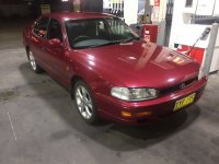
I have two rides at the moment. A Ford Falcon AU Wagon with the 4.0L Inline 6 engine and a Toyota Camry Vienta Grande V6. Think I'm going to improve the sound system in the Ford because the Toyota is a bit long in the tooth now and the Ford has 6x9's in the front doors.

Ford Falcon (AU - Wikipedia)

Just some history on the australian variant of the I6:
Ford straight-six engine - Wikipedia
Ford Barra engine - Wikipedia

I would love the V8 engine but I don't want the fuel consumption.
N5t13DK.jpg

Attachments

  • 31-diyaudio.JPG
    31-diyaudio.JPG
    23.6 KB · Views: 849

Help Finding Source of Low Frequency Noise in Tube Phono Preamp

I recently built a tube phono preamp, and I am having a difficult time tracking down the source of low frequency noise (20Hz and below). My overall noise floor is bouncing up and down and peaking around -25dB or so. Per the attached graph, much of this noise is in the low frequency range. You can also see a couple of spikes around 120Hz and 240Hz likely from DC power. The attached plot was taken with inputs shorted to ground at the PCB. I have tried numerous tactics for tracking down the source of the noise, but have failed so far to figure this out. Here are a few additional facts and thoughts below:
  1. It almost looks like what I'd expect to see with a DC offset issue. Though the output is coupled with a 2.2uF/1mOhm RC filter which SHOULD address that issue. I'm not really sure how to measure DC offset on a phono pre or what normal range of values to expect. I have put a multimeter on the outputs and watched the voltage jump up and down. On a stereo speaker output you typically measure with the volume all the way down, but the phono pre does not have a volume control so I'd expect I can't go by guidelines typically associated with stereo speaker output DC offset measurements.
  2. The preamp is built around 3 12Ax7 tubes. Heaters are wired in parallel running on regulated 6.3VDC from 6.3VAC secondaries on my toroidal transformer (Antek). I'm actually running at around 5.7VDC due to some voltage loss in my rectifier bridge - about to replace that bridge with Schottky diodes to get more headroom. Would running heaters just 0.6 Volts below optimal heater voltage potentially explain my low frequency noise issue?
  3. I've tried tapping around with a platstic tool, pushing components, double checking solder joints, multimeter testing capacitors, moving cables around, connecting and disconnecting my star ground points from chassis, etc. None of the tactics I have tried has helped me narrow down the issue. Anyone have other ideas for things I should try to narrow down the issue?
Any help is appreciated! I can provide further details as necessary.

Attachments

  • 2023-06-04-PhonoPreLowFreqNoise.png
    2023-06-04-PhonoPreLowFreqNoise.png
    181.8 KB · Views: 151

Newbie questions about winding transformers

I've bought a pair of mono amplifiers, hoping to restore and modify them slightly. Unfortunately, one has been heavily modified already and the output transformer has been rewound.
I would like to rewind both OTs to make them a matching pair. Besides the task at hand, transformer winding is a valuable skill I've always wanted to learn.

I have had a look around on this forum and also around the web, but information seems scarce on this topic. I have a seen a few videos online and I think I can pull off the mechanical work. The few questions I have regard the theory and the design of transformers:
  1. I'm planning on buying a rather cheap manual winding machine from Amazon. While I'm at it I will buy the enameled copper wire as well. In order to do that, I understand that I need to know the number of turns and max current for the given winding. I understand I can also parallel multiple wires to obtain a bigger gauge, but given my inexperience and cheap equipment, I'd rather avoid that.
  2. I'd like to receive recommendations for cheap winding insulation materials. I'm interested in both scotch tape (I have seen yellowish transparent tape used as insulation) and pressed paper. I'm looking for something that's easy to get and fairly cheap, hopefully available at a local shop. Does insulation have an influence in design choices? (As far as I've understood yes, but I don't know how)
  3. The main issue I need to sort out is designing. I'd like to understand how to design a transformer. I understand the basics of how transformer work, and I would probably be able to compute the necessary winding ratio for a power trafo. Then, I'd need to decide the wire gauge based on the allowed current, the core size, etc.
    Guidance, references or even books on these steps are extremely appreciated. If there is some sort of spreadsheet or tool to compute these numbers I'd happily use that as a safety check before proceeding with winding.
  4. Winding output transformers is a totally different ball game, as I see oftentimes windings are interleaved, and I'd need to understand when and how to apply that technique. The OPTs I'm going to rewind are push pull, so they're at least easier (and I hope more forgiving) then single ended.
I'm going to rewind both power transformers and output transformers, so I may want to start from the first as they seem easier and more forgiving. Sine I'm rewinding all the iron, I can also change the amplifier design quite a bit. Given the amount of freedom I have in this build, I prefer to learn how to design transformers and not receive a pre-made design without explanation. Any suggestion or reference to a guide is appreciated.
If you want to explain by giving an example, my goal would be to produce 2.5k PP output transformers rated for 60w (I don't know the type of the EI laminations and core, I'd still need to measure them).

For Sale Toroidy Supreme Audio Grade V2

Brand new never used .
2 X Toroidy Supreme Audio Grade V2 transformers with mounting brackets.
Specs : 2X13Vac/500VA
Price / piece : 180 Euro
Price / pair : 300 Euro
Europe sale only and shipping cost not included .
Also have 3 pieces of 2X18Vac /800VA same prices

Attachments

  • toroid top.jpg
    toroid top.jpg
    703.1 KB · Views: 313
  • toroid bottom.jpg
    toroid bottom.jpg
    464.8 KB · Views: 327

EL34 Push-Pull: big temperature differences between the 4 tubes - problematic?

Hi
Is it problematic, if temperatures of the four EL34 tubes in my Triode amp (15W push-pull design) majorly differ in temperature?

I just mounted a fresh set of NOS Svetlana “winged C” tubes (sold to me as a matched quad) and like to make sure, nothing’s wrong.
Of course, I did a proper bias setting (can be adjusted for each pair only). Setting has been stable for two weeks.

I noticed, that the protective grill directly above the tubes stays pretty cool above V4, whilst the surface above V3&2 is too hot to be touched (they are mounted a tad closer to each other). Surface above V1 is hot, but can be touched for a moment.

I then tried to measure “airflow temperature” (please don’t judge me 😊) right above each tube.
I used the probe of an electronic oven thermometer closely above each tube (gave it a few minutes to adjust) to get at least a rough estimate of the temperature differences: V4 is around 55° C “air flow temperature”, V3 around 70° C, V2&1 around 80°C - again: no exact measurements, just a very rough indication…

So: is that a problem? My fear: if temperature is an indication of differences between tubes (bias current or something else), then these four tubes don’t properly match? Or there’s something wrong in the amp?
Sound wise, they play beautifully, no indication of heavy distortion, soundstage is balanced, center is stable.

Thanks for your help in the matter!

Yorkville U15 - unity horn (975$ CAD - 725$ USD)

Pair of Yorkville U15 inspired from Tom Danley design.

The sound condition is perfect but the cosmetic condition is average. The previous owner paints it black. The original color for those pairs was white. Other than that they are more than fine.

Smoke-free environment. Home environment for my part and the previous owner was a church.

Feel free to contact me if you have any questions.

I'm not sure shipping those loudspeakers would be a good idea in terms of cost

975$ CAD - 725$ USD

I'm in located in QC, canada, no shipping

Attachments

  • thumbnail_image0.jpg
    thumbnail_image0.jpg
    237.2 KB · Views: 316
  • thumbnail_image1.jpg
    thumbnail_image1.jpg
    145.1 KB · Views: 198
  • thumbnail_image2.jpg
    thumbnail_image2.jpg
    402.1 KB · Views: 170
  • thumbnail_image4.jpg
    thumbnail_image4.jpg
    296.8 KB · Views: 184

RCF PST351 Amplifier Repair

Hi There,

I am in the process of repairing the amplifier which appears to be an RCF manufacture but rebranded to different names. The output mosfets on the positive rail had shorted. I have replaced them but when testing with the bulb tester, the bulb lights indicating a problem remains. I have checked the SAP's and they don't appear to be shorted either. Diodes seem to be testing fine in circuit as are the other transistors. The only thing that is showing any concern is R37 on the +HV Ref is measuring around 10k. It measures 1m outside of the circuit. R7 on the other hand does measure correctly. Essentially my guess is there is still a short somewhere however when going over the resistors nothing stands to be shorted or way out of range. Does anyone have an idea of an area I should potentially look at to focus on. The resistors in circuit around the mosfets are measuring as per the schematic. I don't think it would be but is it possible the bias is out enough to cause an issue with the new mosfets? I haven't reset it as of yet as the bulb lit.

Thank you for your help in advance.

Attachments

Elekit 8200 Tube Amp (Built) + Tubes!

Up for sale is a fully built Elekit 8200 tube amp, purchased in April 2015. This amp and tube upgrade were featured on Glow in the Dark Audio – I highly recommend reading about it there.

The person I bought the amp from told me it only had a few hours on it – since then, I’ve put another 20 or so hours on it so it’s still fairly new. I’ve opened the amp up to switch listening modes and everything looks like it was assembled with care. There are no loose parts.

It’s currently set to Triode mode which sounds best with my 95db sensitive speakers, however Ultralinear mode sounds pretty great too.

I purchased this amp to experiment with a tube amp + tube rolling, but I’m selling to free up some funds in the ol’ upgrade budget. Prices reflect exactly what I paid for it.


$650 w/stock tubes (+ shipping)

Or

$750 w/stock tubes + upgraded NOS tubes (+shipping)


Condition is Like New or Mint Minus. No major blemishes. Works perfectly, sounds great.

Payment via PayPal F&F preferred, Venmo is OK too. Shipped double boxed. I have 100% ratings on eBay and Discogs - happy to share those with anyone who asks.

--

Includes:
  • Original x2 Electro-harmonix 6L6GC tubes (Russia)
  • Original x2 Electro-harmonix 12AU7 tubes (China)
  • Power Cord
  • Original shipping box, instructions, and proof of purchase

For an additional $100, I will include the tubes I purchased as un upgrade. These are the exact tubes recommended for this model by Glow in the Dark Audio and I agree that they sound great in this amp:

Matched Pair of National Union Radio tubes (90b1)
  • From the 40s or 50s, likely
  • Tubes tested on a Tv-7 tester at 35 and 38. They are 91% and 98% strong.

Matched Pair of RCA 12AU7/ECC82 Clear Top tubes
  • Made in the USA, 1960s
  • Tests very strong at NEW level and tightly matched.
  • Test Results (MaxiPreamp 2, min: 0.8):
    • Tube 1: 1.8/1.7
    • Tube 2: 1.7/1.7

Attachments

  • 81E3CDFA-F636-400D-AB0E-496FC8C80D2B.JPG
    81E3CDFA-F636-400D-AB0E-496FC8C80D2B.JPG
    93.4 KB · Views: 167
  • IMG_2220.jpg
    IMG_2220.jpg
    89.6 KB · Views: 172
  • IMG_2222.jpg
    IMG_2222.jpg
    71.1 KB · Views: 160
  • IMG_2121.jpg
    IMG_2121.jpg
    113.2 KB · Views: 163
  • IMG_2122.jpg
    IMG_2122.jpg
    54 KB · Views: 168

Transistor subs ...

I'm working on an early Sansui 400 receiver, and I'm struggling with subs,,, I keep reading that KSC1815 and KSC1845 are subs for 2sc458,,, but the data sheets don't agree... 458 has Ic=100mA,, 1845 has 50,,, 458 has 115MHz,, 1815 only has 80...

Seems a 2n3904 has covered in all values, but I haven't seen it mentioned... Also saw a sub for 2SC536 is KSC1815,, but that falls short in frequency also... It looks like 2n3904 can cover this one also... I dont see 3904 recommended as subs for Sansui's,,, is it only because of pinouts, rather than a problem with the transistor?? It's pretty easy to just insulate and move a pin to use a very common and dirt cheap transistor, unless i'm missing something major...

Thanks for any input...

SEAS Bragi Speaker Project

I have little confidence in my woodworking skills so need to ask to get right since once glued, well that’s it! I have completed a wood base crossover, cut wire lengths all of which will be installed in the cabinet through the front baffle. That part I am good with, and my crossover assembly fits through the front baffle openings. 😀

Still a noob... This is my second speaker project from a flatpack and hardware kit. I chose a flatpack because I couldn't find anyone local to do the wood cuts for me and do not have a kitted-out workshop to handle these cuts like many folks here. The published basic design does not accommodate for a brace though it does recommend implementing. I worked with the supplier on this, and they provided a center brace design which you can see the in the picture.

My questions center around the order of assembly and gluing the enclosure pieces.
  • Is it best to glue all at once or glue in sections to assemble modularly?
  • Depending on the above… The front baffle is flat glued (no screws), would you recommend it be part of the initial assembly to get a good box brace all round for clamping?
  • The center brace is not tight, there is wiggle room for floating. I am presuming that the gaps allow for better fitment however, is filling this small gap with carpenter glue or No More Nails recommended?
  • Should the center brace be pin nailed for extra hold?

Thanks for any advice and guidance.

Attachments

Front baffle size for open baffle Audio Nirvana 15" Ferrite

I've built the recommended open baffle plan for the Audio Nirvana 15 inch drivers some 15 years ago. It was a rough cut, with shop wood etc. I liked it so much I've kept them, partially in fear that I might not like something if I changed it, since they suited me so perfect. The front baffle is 24" wide and 30 inch tall, and leans back with a gently slope. I use a Aperion dipole AMT supertweeter which cuts in at 16Khz as well, and I use digital speaker EQ to increase bass below 80hz. This year I replaced the old drivers with the new 15" ferrite, it was a nice upgrade.

I am going to finally build a furniture grade replacement, and I am thinking of moving the driver up about 4 inches to closer to ear level. I've also read about changing the width of the front baffle. Right now there is 4 inches of baffle on either side of the driver. What is the effect of narrowing or widening the baffle? Would it be a good idea? I've heard narrowing it might improve soundstage.

I've also thought of tapering the width of the front baffle a bit (so it is a truncated pyramid) with 24 inches on the bottom, and narrowing it so it it just covers the width of driver and continuing that to the top. My theory is it may look cooler, and less right angles is probably better for the sound.

I have also been looking at what material would be the best, I'd sure like to get something denser than the plywood I have. Panzerholz would be perfect, but probably no chance or affordability of that here in the USA anyway. Other ideas??

LUXMAN 117 Help Please II

I am still having problems with a vintage Luxman 117, but narrowed down the issue with one channel dropping out . From what I can see with a flashlight there is a separate board that the RCA inputs are connected and thinking there is lose connection, or cracked around the RCA because with a push - it moves slightly [down] and the sound returns.
Question, has anyone removed the far rear circuit board on a Luxman M-117?

Sony LBT-A590 Amplifier Relay not clicking, Volume knob blinking and no sound

A friend of mine recently moved and didn't want his old system which was the Sony LBT-A590 Amplifier and some other thing which aren't relevant for this thread. when I wired everything up and tried to test it out I noticed when I turned it on there was relay click sound and no sound came from the speakers, I made sure the speakers were fine and the input was fine which the amplifier a screen showing the EQ in which I saw that there clearly music playing. I also noticed that the volume knob light was blinking and when I looked up videos of the device when other people was playing it the volume knob light was solid which has to have a meaning but I can't figure it out, I also tried resetting the device which I couldn't figure it out also. then I downloaded all the manuals (the service manual and the operators manual) to which I couldn't find any helpful information. I made sure that all the fuses were fine, tried searching for fixes online in which I found none beacause the device was very old. any ssuggestions? Service manualOwner's manual

Attachments

  • IMG_20220720_235210.jpg
    IMG_20220720_235210.jpg
    461.9 KB · Views: 669

For Sale Supravox 400 GMF Limited MK2 Revision - 16" / 97dB / 20Hz - 5000Hz / 8 Ohm / 120W / 40cm

A brand new, unused matched pair of Supravox 400 GMF MK2 drivers which were made in 2020 in limited order before shutting down this product line.
One of the best 15"-ish drivers and better than the current 380 GMF which Supravox is selling.
However, I will use 12" in my project so these are unnecessary.
RRP: €1500
Made in France.


70d1071352218630.png

  • Membrane material: Paper;
  • Efficiency: 97dB;
  • Usable frequency range: 20Hz - 5KHz;
  • Impedance: 8Ω;
  • Power: 120W;
  • Fs: 21Hz;
  • Re: 6.5Ω;
  • Qts: 0.2;
  • Qes: 0.21;
  • Qms: 10;
  • Mms: 70g;
  • Bl: 19.6;
  • Cms: 0.47;
  • Sd: 855 cm2
Price for the pair: €999

========

Will be shipped securely.
Location: Sofia, Bulgaria
Contact me here or on email veselin.karavelov@gmail.com

Attachments

  • 20191112_173549.jpg
    20191112_173549.jpg
    409.5 KB · Views: 343
  • 20191112_173550.jpg
    20191112_173550.jpg
    237.8 KB · Views: 347
  • 20191112_173551.jpg
    20191112_173551.jpg
    258.8 KB · Views: 348
  • 20191112_173553.jpg
    20191112_173553.jpg
    258 KB · Views: 336
  • 20191112_173555.jpg
    20191112_173555.jpg
    289.5 KB · Views: 347

New project: 8inch 2way, WG, Scan Speak

As I had such a project in my head for a long time, and drivers + WG available, I decided to to put together simple (well, not that simple) 2way.
Initial thoughts of 21W in 2way were not much in favor of that driver, but the more and more I looked at it, the more I liked it. And it paid off.
21W - excellent off axis behaviour. Breakup at 3200Hz will need extra care, LR4 and lower crossover point, plus capacitor in parallel to main coil. Distortion measurement confirms breakup mirroring in HD3 and HD5.
6600 in WG - in simple baffle with almost zero edge treatment I could not hope for better result. Minor dip at 13k was expected, and proved by listening tests to be no issue.

Cabinet: 37l BR 21Hz.

After initial setup and listening there were several challenges:
1. bass was too deep and dry, midrange little bit in the back
2. trebles too forward, mild hiss signature

1. I have done several iterations of damping material adjustment and I lower the value of primary coil to achieve lower baffle step compensation. The result was exactly what I wanted, clear and clean midrange, impressive well defined bass, and good overall balance
2. I had to attenuate trebles above 2kHz by 0.7dB, and take care of 7-10kHz area, and 2.5kHz area. This brought the right balance of detail, clarity and smoothness I know 6600 was capable of.

Measurements were done with no gating, smoothing 1/12. SPL calibrated, distortion measurement with mic distance 30cm, 2.83V drivers and 6V complete loudspeaker.

Full writeup: https://pkaudio.webnode.cz/21w-6600-wg/

Attachments

  • 2way 8inch photo.png
    2way 8inch photo.png
    221.4 KB · Views: 508
  • 2way 8inch Vituix Six pack.png
    2way 8inch Vituix Six pack.png
    111.6 KB · Views: 365
  • 21W distortion.png
    21W distortion.png
    64 KB · Views: 289
  • 21W FR horizontal 0-90.png
    21W FR horizontal 0-90.png
    57.9 KB · Views: 246
  • 6600 distortion.png
    6600 distortion.png
    58.9 KB · Views: 261
  • 6600 FR horizontal 0-90.png
    6600 FR horizontal 0-90.png
    70.4 KB · Views: 252
  • loudspeaker distorsion 6V.png
    loudspeaker distorsion 6V.png
    73.2 KB · Views: 326

Questions : Amp Gain and AV Receiver Pre Out

Hi Everyone.

Can someone please help me with these questions.

1. What is the Gain of F5 Turbo V3(44V Rail voltage) and Aleph 2(55 V Rail voltage).
2. What is the Gain of AV Receiver SR6007 (https://www.marantz.com/en-us/product/av-receivers/sr6007)
3. I'll be using PRE OUT from AV receiver to feed F5T and Aleph2. Can I use PRE OUT SW1(Subwoofer1) and SW2(Subwoofer2) as input to Aleph2?


Thank you

Attachments

  • Img.png
    Img.png
    155.6 KB · Views: 93

Looking for IGBT amplifier schematics?

Hello, I only know about IGBT for powered a 1500V motor in a train, a good compromise between Transistor and MOSFET.
But in the audio world I would like to know how it sounds. The only amplifier schematic I see is in this french magazine :
http://www.electronique-3d.fr/PDF/Ampli-90W.pdf
Do you know about other Igbt amplifier ? Have schematics ? Heard to the sound ?
Thanks in advance 🙂

Sell capacitor 1,000uf 6v Brand ROE

Sell capacitor 1,000uf 6v, sell as a set, set of 10, price 5 usd, direct mail from Bangkok, pay by paypal plus shipping (shipping cost will be informed later when knowing the destination address)

Attachments

  • 1686635803793.jpg
    1686635803793.jpg
    207.6 KB · Views: 64
  • 1686635803600.jpg
    1686635803600.jpg
    205.3 KB · Views: 68
  • 1686635803243.jpg
    1686635803243.jpg
    196.1 KB · Views: 65
  • 1686635804740.jpg
    1686635804740.jpg
    173.8 KB · Views: 60
  • 1686635804324.jpg
    1686635804324.jpg
    243.4 KB · Views: 59
  • 1686635805585.jpg
    1686635805585.jpg
    218.5 KB · Views: 58
  • 1686635805139.jpg
    1686635805139.jpg
    221.8 KB · Views: 60

The most robust dome tweeter available?

Hey folks…..so I’ve got to put together a very low profile center channel for a 7.1.2 Atmos system for a client…..can’t be taller than 4.5” cabinet so a dome is a must. Nothing available commercially that won’t have severe off axis issues so I’ve got to get that XO point down to 1k with a steep slope. Its gotta be able to keep up and do 105db……any domes that can do this currently on the market?

  • Locked
Churchill Downs Shutting Down Horse Racing Operations

Churchill Downs announced last week that they are shutting down horse racing operations at the track to examine safety measures.

Also, here is an excellent piece by a lifelong horse person regarding the current racing situation.

https://www.cnn.com/2023/06/08/opin...orse-racing-deaths-doping-ban-irby/index.html
  • Like
Reactions: adason

For Sale Digital Audio Labs CSX-01 CardDeluxe

24/96 PCI professional audio card, was a recording industry standard, great for measurements $100

CardDeluxe WDM/ASIO device driver (5.10.3523) (Windows® XP/Vista/7; 32/64-bit)

CardDeluxe WDM ASIO Driver for Windows 7/10 64 bit Driver

Here are FFT plots, driving inputs with 1Vrms from AP and sending 1Vrms from CardDeluxe to AP. I don't have PCI slot for it anymore

Attachments

  • IMG_1686.JPG
    IMG_1686.JPG
    228.5 KB · Views: 141
  • IMG_1687.JPG
    IMG_1687.JPG
    168.5 KB · Views: 142
  • left input.PNG
    left input.PNG
    18.5 KB · Views: 128
  • right input.PNG
    right input.PNG
    18 KB · Views: 128
  • left output.PNG
    left output.PNG
    6.5 KB · Views: 130
  • right output.PNG
    right output.PNG
    6.6 KB · Views: 145

NOS Parts: Carbon Comp (30+ 2 watt values) and Metal Resistors; WW 10 Ohm Pots; 1W Bourns Trimmers; and More!

Hello,

I am downsizing my apartment, so I'm trying to sell off some parts. Stock your parts bin! I will beat prices at surplus retailers. Due to the hassle of shipping, I don't really want to sell individual components. Please only reach out if you are interested in ordering a decent quantity. This will work best if you're a tech etc. Big discounts for volume purchases.

I am located in the US and willing to ship internationally.

Wirewound 10 Ohm 5 Watt Linear Pots (bulk):

I bought these from the estate of Dick Sequerra and have been selling them for a while. I think they were used in speaker crossovers.

They are flawless and un-corroded on the inside. Every single one I have tested has been good electrically. However, the oil in the shafts is a bit stiff, so they turn best if they are re-lubricated. Also, the terminal plating has corrosion which should be wiped off with contact cleaner. Afterwards they work well and take solder.

Selling in as-is condition. I have two boxes, one of which is full (1,000 potentiometers) and the other of which has about 900 remaining. I also have a couple hundred loose. They come with washers and nuts for mounting. 5 watt wirewound pots cost like $5 a piece now from major distributors; I'm willing to let these go for like $.20 a piece. A great deal if you use these frequently. Would love to sell a whole box.

Carbon Comp Resistors

I have a ton of carbon comp resistors, mostly 2 watt, but also very large quantities of some other values. Please reach out with the value you're interested in and I'll give you a quantity. I have many boxes of high-value resistors (1M ohm plus) and would really like to get rid of these.

All of these resistors are totally NOS, never soldered or used. Some were stored loose and have slightly bent leads. There is no water damage or anything and the paint is in great condition. Some of them do have slight corrosion on the leads as expected given the age. I might have missed some values, so if you're interested in a value I don't have listed, feel free to PM.

2 watt values:

13
15
160
240
330
390
420
430
560
620
680
1.8K
7.5K
8.2K
9.1K
11K
13K
16K
25K
56K
62K
82K
120K
130K
360K
820K
910K
1.2M (very low price)
1.8M (very low price)
2.7M (very low price)
3.3M (very low price)
5.6M (very low price)
6.8M (very low price)
12M (very very low price)
22M (very very low price)

1 watt values :

18
51 (500+)
750
12K
2.2M (500+; right angle leads)
6.8M

1/2 watt values:

3.9K
4.7K (I have like eight boxes of these; probably 6,000 plus in total. Some have pre-bent leads. Would love to sell some boxes.)

1/4 watt values:

270 (1,000+; good for cathode bias)
390 (good for cathode bias)
1K (good for cathode bias)
2.2K (1,000+)
4.7K (good grid stoppers)
10K
33K
100K
240K
330K
1M (500+; good for grid leak)
10 M (1000+)

I haven't catalogued all my 1/4 watt CC resistors yet, so let me know if you need anything specific and I'll look.

Metal Film/Oxide (have hundreds of each of these):

Some of these are pretty rare and unusual, so if you enjoy parts rolling they could be fun.

3.01K 1/4 W 1% (RNR60C3011FS hermetically sealed mil-spec resistor by MEPCO/Electra. The resistor is hermetically sealed inside an outer glass shell. Extremely cool appearance and super expensive from a real distributor. Datasheet says these are used in missile guidance and other mission critical applications. Makes for a hilarious grid stopper or cathode bias).

5.2K 1/2W (?) 1% (Says EKC on resistor. They have a loose plastic outer shell, no idea why, never seen anything like it. Think 1/2 W based on testing and size but not marked. Very cool appearance. I use them as grid stoppers).

9K 1/2W 1% (RN60D9001F Mil-Spec metal film; have 1000+ on reel tape).

18K 1/4W 1% (RL07S183G; precision metal film resistors in great condition on reel tape).

47K 2W (?) 5%ish (Interesting resistors, military drab green color. Looks like a very early metal film/oxide type. Only marking is "47K" and a dot of orange QC paint. Based on my testing they handle 2W but 1W or less is preferable. They seem to be about 5% but have no tolerance marking. Lead plating looks exotic -- has a slight golden sheen. Each one is packaged individually in a cardboard tube. Great plate loads).

180K 1/2 W 1% (Corning Glass Works N20. There is a datasheet for these online. A high quality, low drift part. Jet black vintage appearance -- they look great).

Bourns Trimmers:

25K 1W 25-turn
(3250P-67-253; I bought these at a military surplus auction and have the demil paperwork. These are high-quality Bourns trimmers in their original tubing. Great for critical applications that require the trimmer to dissipate a bit of heat, such as AC balancing differential plate loads. A somewhat exotic part not available from normal distributors).

Axial Tantalum Capacitors:

180 uF 25V 20%
(NCI HNW 7449; These are expensive axial tantalum capacitors with a grey metal body. They have the same high-quality look as vintage Sprague electrolytics. Great for cathode bypass or decoupling. Tested at rated voltage and guaranteed working).

DPDT Switches:

3A 250V / 6A 125V, panel mount
with solder lugs (Made by UND Lab Inc. A great, chunky vintage DPDT switch. Comes with plated metal inner mounting nut and black anodized outer nut which matches color of switch. Very similar (if not identical) to toggle switches used in vintage test gear like Power Designs. I have a lot of these and would love to sell 10-20 at a time).

Nakamichi MB-K1000

I just purchased one of these nakamichi mb-k1000 music kiosk setups which I suspect with the closure of some music stores will become more available as time goes by.
I'm waiting for it to arrive. Does anybody here have any experience with these... there seems to be very little info available on the web.

I play so little CD these days, almost entirely LP with some streaming music, I thought it might be interesting to have this to play around with. It may end up collecting dust or I might get some use out of it, we will see

Paraller SE E88CC/KT150 tube amp design

Hello 🙂

I am designing my first tube amp. Before I start assembling, I'd like to get approval or advices from more experienced constructors 🙂
The project is a simple, two-stage parallel single ended, based on the e88cc/6922 and 2 x KT150 tubes per channel.
The amplifier is designed for the triode mode, although the ultralinear option is also provided.


Low THD was not the goal of the project. I care about a favorable ratio of even to odd harmonics and a warm, saturated tube sound. The LTSpice simulation shows just over 5% of the second and 0.2% of the third harmonics at full power. Of course, in real life, the results may be different than simulated 🙂


Less parts
No grid stoppers for the driver tubes - the volume pot will fulfill this role(?)
No grid stoppers for the power tubes
No coupling capacitor at the input - I assume that the capacitor is at the output of the source (DAC)


Cathode bypass capacitors for the driver: Nichicon FG. The Nichicon KZ is positioned higher, but its sound is supposedly less warm.
Elna Silimic might have been better, but nowadays it's probably hard to get a better version (ARS, AXF) than the standard RFS.


Driver anode choke:
Lundahl LL1668-15mA
(Coils in Series, DC Resistance 680Ω, x 235V~ 100Hz Ripple, 15mA 167H)
The choke is designed for 15mA, but according to the website
http://jacmusic.com/lundahl/applications/How-to-bias-the-LL1667-LL1668.pdf
...DC current can be exceeded if the AC signal voltage is lower.
LL1667-15mA (Coils in Series, DC Resistance 2400Ω, x 390V~ 100Hz Ripple, 15mA 270H) has a higher inductance, but the forums say that 1668 sounds better than 1667.


The output transformer has 1500 ohm impedance, so each of the two power tubes sees a little over 3000 ohm (the screen current must also pass through the transformer's winding and it seems to raise the impedance)
I am also considering a transformer with an alternative lower impedance tap to achieve more power.


PSU is a very important part of every amplifier - in order not to make a mess in this thread, I will present the PSU circuit (as well as a fixed bias circuit for power tubes) in another thread, when I get approval for this project.


So...
  • Won't it explode? 😉
  • Does the presented circuit make sense?
  • Is there a chance that the construction will sound decently?
  • Did I forget something?


Thanks in advance for any suggestions or comments!
Rafal

Attachments

  • TubeAmp.png
    TubeAmp.png
    142.3 KB · Views: 680

DavidLouis 4ohm 104BE25-4 Pure beryllium dome tweeter Nd magnet & davidlouis BE28 pure beryllium Be dome tweeter speaker Nd magnet. ANY GOOD?

Hello all,
Does anyone have any experience with either the DavidLouis 4ohm 104BE25-4 Pure beryllium dome tweeter Nd magnet or the davidlouis BE28 pure beryllium Be dome tweeter speaker Nd magnet? I can't really find anything online. (good or bad...) Please advise... Thanks in advance.

Attachments

  • EA46FAB0-5027-4161-9DF5-7D6E1ABFC9CA.jpeg
    EA46FAB0-5027-4161-9DF5-7D6E1ABFC9CA.jpeg
    214.4 KB · Views: 169
  • 492A3FCA-1B66-40CC-910F-84D561D8A97A.jpeg
    492A3FCA-1B66-40CC-910F-84D561D8A97A.jpeg
    188.8 KB · Views: 136

6V6 amp in LTSpice

Hi guys, this is my first post on the forum.
I want to ltspice my amp based on 6v6, but I don't have much idea, especially in the output transformers, I did what I could by copying some examples from the forum.

The original schematic is on this page, if anyone can give me clues on how to do it and test it.
https://diyaudioprojects.com/Schematics/DIY-Push-Pull-PP-6V6-Tube-Amplifier/

I leave you the file of what I did
it would be greatly appreciated

thanx a lot

Attachments

Twisted Pear Audio Parts

For sale are new, unused parts for Twisted Pear Audio (TPA) products:
  • 1x Buffalo III DAC with full series regulator set (3x Trident, AVCC)
  • 2x Buffalo II DAC with IVY III v1.0.1, AVCC, 3 Trident v3.0
  • LCDPS Assembled & Tested (Panasonic & Elna caps)
  • Placid HD Assembled & Tested (Panasonic cap)
  • S/PDIF Transceiver - Sold 05/08/23
  • Volumite Base Kit, Firmware for Buffalo III
  • 2 of Toslink Optical Input Module - 1 Sold 05/08/23
  • Legato 3.1 board with Parts
  • AVCC SRA 2 V-1.0 3.50V
  • Trident regulators:
    • 2x VDD 1.2V v1.1
    • 2x DVCC 3.3V v1.1
    • 1x VDD_XO 3.3V v1.1
    • 3x AVCC AVCC_SR_1.0
    • 2x AVCC SRA V-1.0 3.50V
  • 1x Placid HD 3.1 Power supply board with all parts
  • 2x Placid HD 3.1 Bipolar Power supply board with all parts
  • Toroidal transformers for Placids
    • 1x 25VA 9V, double secondary AnTek AN-0209
    • 3x 25VA 15V, double secondary AnTEk AN -0215
    • 2x 52VA, 2x 15V, 1x 9V by Primrose Audio Design (ideal for dual mono build perhaps)
  • Legato 1.0.3 board with all parts
  • Legato 3.1 board with all parts

The part would ship from Massachusetts, US. Please send a private message.

IMG_6658.jpg

IMG_6659.jpg

IMG_6662.jpg

IMG_6632.jpg

IMG_6636.jpg

IMG_6672.jpg
IMG_6673.jpg

Cabinet material Measurement

Here are some measurement from the excellent German magazine (what happened to the football team?)
The setup a wide band driver set in a box within a box

A front baffle is added and two things are measured. The sound througput through the board and secondly the vibrations of the board is measured with a contact microphone

Then a set of board are compared and with 19 mm MDF as the standard both for transmission and vibration levels
Picture 1 Findings
I. The 16 mm is very close to the 19 mm in both accounts even if thinner
II. "Concretchipboard" While hard to find superior to MDF
III. Beech plywood, slightly inferior to MDF
Picture 2
I.28 mm MDF better than 19 mm but not by so much as the increased thickness suggest
II. 20 mm Slate (stone) way better than anything else!
III. 19 mm Chipboard, while inferior to MDF it is cheaper so a given amount of investment gives a thicker board...
IV. Blockboard 19mm inferior to both MDF and chipbord

I am familiar with the BBC papers that guided both the LS3/5A and the Spendor BC1. Both had thin walls and a lot of damping to get the resonances out of the harmful midrange and down to the bass to cause less harm

Attachments

  • HH-Testsetup1.png
    HH-Testsetup1.png
    40 KB · Views: 433
  • HH-TestSetup2.png
    HH-TestSetup2.png
    54.1 KB · Views: 485
  • HH-Test-Boards1.png
    HH-Test-Boards1.png
    407.5 KB · Views: 467
  • HH-Test-Boards2.png
    HH-Test-Boards2.png
    527.7 KB · Views: 461

Help Identifying an Oddball Tube Amp Chassis

Hi All!

I picked up this amp chassis for $20 today. No tubes or documentation included. The only markings are a stamped circle with "32E" inside. The over-all circuit appears to be push-pull using some kind of octal power tube like 6v6, 6l6, etc (pin 1 unused, pin 3 [plate] tied to one side of opt primary, pins 2 and 7 heater). Here's where the odd comes in. The screen grid pins (pins 4) are tied to the cathodes (pins 8), which are tied to what appears to be a filter capacitor positive voltage node. Both grids are tied together, and go to the 9-pin octal style socket. The power supply uses solid-state rectifiers, and appears normal enough. There appears to be both main B+ and a single-diode negative voltage source, and there is what looks like a bias POT with no guts which is NOT tied to the power tube grids. I can't figure out what exactly its purpose was. There doesn't appear to be any specific grounding scheme, as some grounds go to chassis, while others tie together in a semi-star style. My gut instinct is to just gut it and start a build from scratch. However, if this is a bit of a rare amp configuration worth a possible resurrection, I'd consider that undertaking.

Any help/input appreciated!

Attachments

  • 20230611_201633.jpg
    20230611_201633.jpg
    318.8 KB · Views: 136
  • 20230611_201652.jpg
    20230611_201652.jpg
    273.1 KB · Views: 128
  • 20230611_201702.jpg
    20230611_201702.jpg
    260.5 KB · Views: 124
  • 20230611_201815.jpg
    20230611_201815.jpg
    361.3 KB · Views: 128
  • 20230611_201951.jpg
    20230611_201951.jpg
    308.5 KB · Views: 116
  • 20230611_202355.jpg
    20230611_202355.jpg
    545.5 KB · Views: 116
  • Image1.jpg
    Image1.jpg
    85.2 KB · Views: 118

Coral CX-5 tweeter blown

Hi

The tweeters have blown in my coral cx-5 speakers. They are rated at 60w music, which, i assume could be around 30rms? The cutout for the tweeter is 5.5cm, just below the bottom of the cut out is internal bracing (as per photo). I upgraded the crossover and found in another forum, some one had drawn out the schematic for the crossover. I used jansen for the tweeter , mid LCR (ampohm), woofer just cross caps. Resistors, i tried the W22 from element14. Really nice sounding speakers, the midrange being its best drivers. Sounds fine without the tweeters. The attenuator doesnt appear to work, it did for the mids not the tweeter. I carefully did pull it apart and cleaned it. Its either my wiring or something else.

Ive had success with the Seas H1283 in my ESM / Seas Kenwood bookshelf speakers. I am learning towards it, and i am not sure if it suits this particular crossover.

coral cx-5 crossover.jpeg


P1460372.JPG

P1480566.JPG

P1480575.JPG

FS Biosciencegeek cMOY Headphone Amp

For sale mint (see what I did there? LoL) cMOY Headphone Amp. Asking $60. As made by Biosciencegeek, it doesn't look like he is selling them anymore (on E.....y). Using Burr Brown OPA2227, 9 volt batteries are set up to run in parallel. Base boost/gain switch, can be powered externally. Plugging in headphones turns it on.

Attachments

  • PXL_20230605_025508689.jpg
    PXL_20230605_025508689.jpg
    290.7 KB · Views: 107
  • PXL_20230605_025442878.jpg
    PXL_20230605_025442878.jpg
    312.3 KB · Views: 97
  • PXL_20230605_030120247.jpg
    PXL_20230605_030120247.jpg
    648.6 KB · Views: 123
  • PXL_20230605_025545585.jpg
    PXL_20230605_025545585.jpg
    406.9 KB · Views: 114
  • PXL_20230605_025537338.jpg
    PXL_20230605_025537338.jpg
    380.9 KB · Views: 113

Cassette decks with ribbon type connectors...

Hi, I'm looking to dip my toe into cassette tapes. I have a load of old cassettes I'd like to listen to and possibly digitise. I was looking at the TEAC H300 but these seem to hold their value quite well and are a little pricey, probably because they have a standard RCA stereo output.
I've noticed loads of Technics decks and other makes which are of a similar era and type as the H300 which go for peanuts. A lot of them use proprietary ribbon interconnects.

Im wondering if anyone has traced the connections back to figure out which wires within the ribbon cable carry the left right analogue audio signals and then retro fitted RCA sockets in the chassis of one of these decks? Seems like it should be easy enough to do.

First PCB design, any feedback before I order?

Hey, I've been working on a mic preamp in a stompbox based off this TapeOp article. I swapped out the tubes for Soviet subminiature 6N16Bs and added a H-pad at the end to reduce the voltage back to microphone level. I simulated it in KiCad and tweaked the plate and cathode resistor values until I had something I liked, and also added an L-pad after the second preamp stage to prevent the cathode follower from clipping. Anyway, I've sourced the parts, found a Hammond enclosure, and designed the PCB. I think I've followed all of the rules - 45 degree angles, keep audio and power ground separate, star ground for audio, avoid crossing traces, and if it's unavoidable, have them cross at a 90 degree angle. This is my third PCB design iteration and I think I'm ready to place an order. But before I do, I thought it would be wise to ask for feedback.

K1 and K2 are relays controlled by the footswitch.
T1 is the input trafo, T2 the output trafo.
There are two POT_GNDs because the cables are shielded.
U1 is configured as two cathode-biased preamps, and U2 as a White cathode follower.

The trafos and balanced input and output connect on the bottom of the board.

The footswitch has its own pcb (at the bottom) that I'll cut off. It will stand above the the empty spot at the bottom middle.

C8 is a decoupling cap, the others are all coupling.

The power source is a tiny (25mm x 25 mm) nixie tube power supply. It will sit under the board, below the output trafo. I'm going to add a grounded copper pour under the output trafo to provide some shielding, but if that's not enough, I'll have enough clearance to put a shield between them.

The audio path goes from the balanced input XLR (IP2/IP3) to the input trafo primary (T1-ORG/T1-BRN). The unbalanced secondary (T1-GRN) goes to via the grid stop (R19) to U1, then from U1 to POT_OUT to a gain pot, then to POT_IN, to C3, back to the second triode in U1, then to R16. That goes directly to the cathode follower U2, which outputs to to C6, then to T2-B (output trafo). Finally, the secondary output (balanced - T2-G/T2-Y) goes through the H-pad at the top left before entering K2 and finally to the output XLR (OP2/OP3).

When the coils of K1 and K2 are disengaged, IP2/3 and OP2/3 are connected directly and the H-pad becomes a dummy load.

Any feedback on my placement and routing? F.Cu is red, B.Cu is blue. All audio ground is routed on B.Cu.

Thanks!

Screenshot 2023-05-06 at 8.13.24 PM.png

Greetings from Finland

Hello! I've been lurking around the forum for about three years and decided to join and wanted to introduce myself.

First of all I'm amazed and grateful for the huge amount of knowledge and experience the members here have and that they are willing to share it too. Without it my road to designing and building my first speaker set would have been a lot harder. Been listening to them for about 18 months and I like them although the enclosures require some ( a lot of ) finishing but I've never gotten around to it since aesthetics are not that important to me
20230611_211618.jpg
  • Like
Reactions: Juhazi

Mystery ‘Concord' mixer amplifier with mystery output transistors

Hello,
I am trying to fix this mixer/amplifier:

IMG_20230608_200638083.jpg


Unfortunately, I can't find any information on it, let alone a schematic. does anyone have a clue?

The problem seems to be the output transistors, at least one of them (the NPN one) measures short circuit between collector and emitter. Can't be good. But here to, I am unable to find any reference. Here they are:

IMG_20230608_200752270.jpg


Looking at the PCB, I see no driver transistors, so I think the above individuals are darlingtons. But how to know? with my multimeter on diode check, the readings are:

NPN:

C to E short circuit
B to E 0.6v
B to C 0.6v
E to B 1.8v
C to B 1.8v

PNP:

C to E infinite
E to B infinite
C to B 0.6v
B to E infinite
B to C 1.5v
E to C infinite


Any help is very welcome,

Gijser

MathAudio Room EQ for Foobar2000

mathaudio-room-eq.png


Features:

  • Corrects deficiencies of room acoustics (multipoint compensation).
  • Corrects acoustic imperfections of speakers.
  • Optimized for maximum accuracy of the correction.
  • Corrects both amplitude and phase components of frequency response.
  • Quells resonance peaks of frequency response while leaving the deep notches to prevent large excursions of the speaker diaphragm. Avoids the muddy sound of conventional linearizing equalizers.
  • Manually adjustable level of compensation allows one to reach the maximum transparency of the sound.
  • Supports high sample rates.
  • Applies 64-bit signal path throughout.
  • Works with USB measurement microphones (e.g. MiniDSP UMIK-1) or standard measurement microphones (e.g. NADY CM100 or Dayton Audio EMM-6).
  • Supports microphone calibration files.
  • Applies a patented method of frequency response correction.
The plug-in is free.
Download: MATHAUDIO - Download
Any feedback is welcome.

MEMS Cartridge - Micro Condenser Microphone for the pickup

A patented new product from a small Japanese company. $5000. It uses 1mm condenser mics for smartphones. I'm a bit skeptical about this, but it may work very well. RIAA EQ / phono amp is not required.

The Miyaji-type MEMS cartridge has an amplitude-proportional characteristic that uses a very small high-sensitivity condenser microphone for the pickup.
It is a structure that guides the vibration of the cantilever to the left and right sound conduits and captures the sound pressure with a microphone.
The sound pressure transmitted to the microphone is equalized in the shape of the sound conduit, and the frequency characteristics of 20Hz to 20KHz are adjusted to be almost flat in the test record and aged. Since the frequency characteristics are attached to the characteristic table actually measured for each product, high-quality audio signals can be obtained. Since the MEMS microphone is a condenser type microphone, it requires a power supply and uses a dedicated head amplifier.


(Google translate)

https://arsound-jp.translate.goog/m...l=auto&_x_tr_tl=en&_x_tr_hl=en&_x_tr_pto=wapp

Help with Center DC Adjustment - Sansui B-2101

Hello everyone

I recently restored a Sansui B-2101 power amp and really tried hard.....
All caps were selected according to their specifications (low ESR, low leakage, etc.) The same values (left - right side) as possible and really the best quality (which was affordable for me). Transistors KQ 2-9 matched in pairs (as best as possible).
New thermal paste and everything you need to do a good job.

But today when comparing, I first noticed that there are errors in the SM. VR3,4 are shown reversed and the pin assignment on the 5-pin test point (picture 4-2. Top View) is different than in the picture next to the comparison table (2-2.). So far everything is still ok, since it was noticed early on.
The main problem, is the center dc 0V adjustment with VR2. There is no stable value to get. I have already exchanged the variable resistor for a 100 Ohm type because the fluctuations during the adjustment were too severe. However, I can only bring the voltage to around 0V and then the voltage starts to drift. The smallest changes on the controller let the voltage run away immediately. The adjustable range between +/- 200mV is only about a 10 degree radius.I can no longer imagine a solution.So here's my question to the real experts, is this possibly a design error or how can this happen? Is there possibly a solution that saves my day?

Attached are two pictures of the manual to understand what I'm writing about.
Thank you in advance for any help and have a nice day
Sansui madness.jpg


Sansui madness 2.jpg

Old and knackered but working Magnum Dynalab Tuner and Signal Sleuth

I have had this tuner sitting around for years, last time I lived in a place where I could get FM reliably it worked well. I bought it from eBay many years ago and it had a bunch of dodgy mods done to it. I removed some of the more egregious ones and cleaned it up, and made sure it was working well. I didn't pay a lot for it and neither should you. This also comes with a signal sleuth also by Magnum Dynalab, I never found it particularly useful, but you might.

I'm looking to give these a new home with someone who might use them. Offers accepted.

Sheldon

FMTuner - 7.jpeg
FMTuner - 6.jpeg
FMTuner - 5.jpeg
FMTuner - 4.jpeg
FMTuner - 3.jpeg
FMTuner - 2.jpeg
FMTuner - 1.jpeg
  • Like
Reactions: JRKO

Threshold SA/2 Amps One running hotter than other

I just purchased a pair of Threshold SA/2 optical bias amplifiers in their original unrestored state. They sound amazing with no noticeable issues. However, I have noticed one amp runs about 7 degrees warmer than the other(100F vs 107F)at the same midpoint on the heatsinks. Regardless of input or speaker swapping L for R channel it is always 7 degrees warmer. Should I be concerned or is this likely a bias issue I could address myself as an amateur? Or is this within a normal range of difference between amps?

Thank you

Charles

How to unstick transistor?

I am trying to replace the output capacitors in my KEF 30b subwoofer amplifier. I cannot get to the under side of the capacitors as the circuit board is connected to two transistors that seem to be stuck to the heat sink? Any ideas on how to unstick these?

Attachments

  • IMG_5996.jpeg
    IMG_5996.jpeg
    376.4 KB · Views: 146
  • IMG_5998.jpeg
    IMG_5998.jpeg
    422.2 KB · Views: 137
  • IMG_6002.jpeg
    IMG_6002.jpeg
    435.4 KB · Views: 150
  • IMG_6007.jpeg
    IMG_6007.jpeg
    406.4 KB · Views: 140

For Sale Leaving the hobby

Everything is for sale. Valves, small tools, soldering gear, semiconductors, chip amp parts and PCBs, transformers, etc.

I'm fully aware the there's quite a bit of junk here, but what doesn't sell is going in the skip - if you can use something make an offer. Preference given to larger offers - make me an offer on all of the caps, or all of the semis, or all of a certain type of valve, for example. If you cherry pick the best stuff, the prices aren't as negotiable.

Prices are Australian dollars and do not include shipping. Payment by EFT is preferred.

Edit: Prospective overseas buyers take note - shipping from Australia is quite costly. $60 for 2kg seems typical.

Anything that is mains connected is for 240v/50hz with Australian style plug.

I don't have the ability to test any of the valves, so price in some duds if that concerns you. All of the valves were acquired between 2002 and 2006 from reputable sellers. 99% would have been new or tested as new - I didn't buy garage sale stuff.

There is a bit more to be added to the list. You'll notice not everything is photographed - that will be coming at least for the remaining valves, transformers and vinyl. If you want a photo of something send me a private message. It may take some time to get to it. Please be patient.

Inquires by private message please.

The Big List

DC servo-loop over several amplifying stages?

Considering a 3-stage phono amplifier with a DC servo, measuring at the output and injecting the correction signal in the first stage;
are there any concerns in an DC-servo arrangement as shown below, where the servo-loop includes 2(3) gain stages?
I don’t want to build this amp like this, so please ignore everything else.

Screenshot 2023-06-06 105308.png
  • Like
Reactions: hpavictor

Resonances hidden from waterfall response

While waterfall responses are widely used to detect resonances I doubt they can reveal all of the resonances. Some things come up in my mind:
  • resonances of coil, spider as they might produce little or no soundpressure and/or sound is radiated backwards not reaching the measuring microphone.
  • resonances on the surface of the cone which are out of phase and so sound may cancel before reaching the microphone. At lower freq even close distance of the microphone might not help or only partially.

One could argue that if the microphone cant catch the resonance our ears wont either. But I think all resonance are detrimental as they also alter the sound envelope at the start of the signal, not only at the decay.

Is it true that standard waterfall response fail to 'see' all resonances? Are there better or more sophisticated methods which can? Can the onset of the signal (instead of the decay) reveal resonances not shown by the waterfall response?
  • Like
Reactions: cumbb

Should I modify my existing crossovers?

Hi, I own a pair of ADS L1590/2 speakers. These speakers sound nearly perfect, except for a little mid-bass boom. There is an "Umm" sound in the male voice, which is a little bit annoying to me.

The low-pass filters on the woofers are pure second-order, without any other circuits, consisting of a 3.5 mH and a 100 uF capacitor. I have a 4 mH coil and a 130 uF cap for spare parts. I'm thinking of modifying the crossovers by using these components.

Then, I tried simulation on the old and new crossovers, and there were no problems with the results at all—smooth frequency responses and impedance curves.

However, my friend suggested to me that, in the second-order filters, the inductor value should not exceed the driver's impedance, which here is 3.8 ohms. So, I wonder whether his statement is true. Anyone could confirm, please?

DIY Class D Guitar Amp & Shielding / Ground

Hi.
I'm currently experimenting with a class d board I bought on eBay and experiencing some noise.
I assume (I'm a noob) that the reason for this is that I just connected the board to a preamp attached power and a speaker to the board.
There is no central shield / ground from the board. Maybe someone can point me into the right direction because simply googling it turned not to be as successful as expected. But maybe I searched the wrong terms 🙂

In case I decide to use a metal housing, my questions are:

1) Do I need to connect the power supplies minus/ground to the metal housing ?
2) Do I need to connected the inputs minus to ground aswell ? I opened up some plastic distortion pedals to compare and it seems like their inputs are not wired to ground..
3) Do I have to do the same for the output / to speaker minus ?
4) If the above needs ground, do I need an additional groung wire to connect the (metal) input jacks to ground, or is it sufficient enough to use the connection to the metal housing they already have?
5) Can I simply add a low-pass filter cutting off at 6Khz before attaching a speaker or is filtering better on the input ?
6) If I'd like to amplify only 100hz to 6-7Khz to the class d board, restricting it with a passive bandpass, would it be better to do it on the input or output ?

I'm sorry if these questions may appear somehow stupid, but I hope someone can guide me into the right direction or provide some answers/clarification.

Have a nice and sunny day and thanks in advance!
audi0n00b

Adding pre out to Onkyo HT R494

hello everyone, so I’m trying to mod my Onkyo receiver, and I would like to add some pre-outs to it

I have been looking at the service manual and if you look at the picture below, I think this is the preamp section where I should tap to get the pre-out.
This is the first time I’ve tried doing anything like this, and I would really like some tips.

Login to view embedded media
thank you very much. Looking forward to start a discussion.

Clarity SA caps and some others

New unused 6 x 2,2uf 630 V caps Clarity SA + Clarity SA 0.22uf 630v + some used Jantzen mkp and pair of white big caps.Also pair of Mundorf Evo oil caps 4.7uf 450v.
I dont need tjis anymore and will never use this,so just make some resonable offer and this are yours.Shipping inside EU will be 7,50 euro for all caps with track.

Attachments

  • 20230611_193952.jpg
    20230611_193952.jpg
    864 KB · Views: 91
  • 20230611_193949.jpg
    20230611_193949.jpg
    774.5 KB · Views: 91
  • 20230611_193956.jpg
    20230611_193956.jpg
    740 KB · Views: 82
  • 20230611_193959.jpg
    20230611_193959.jpg
    918.4 KB · Views: 85

Making a new sealed box for my 2-way

I have a very good sounding two way box, using an excellent 8" low-mid and a soft dome tweeter.

The woofer was designed and built by a friend of mine who manufactured and sold speakers in Argentina. Unfortunately he passed away about two months ago, and we didn't get to do this mod together. So now I am on my own.

The idea, as we talked about was to build a new larger box, holding all three drivers. We were still going to see if there would be wood plate separating the 8" + tweet from the NHT 1259 sub bass speaker. A separate amplifier would feed the NHT, with passive 2nd or 3rd passive low pass eq on the amp. The sub output would be fed from receiver RCA output. The idea was not to use a large inductor as passive crossover on the sub box.

Unfortunately that option would force the use of just one sub for both channels. My late friend had done many tests and measurements on his premises and he arrived to the conclusion that what is always said that very low frequencies presented themselves as just one single wave, instead of two different ones for each channel is not exactly so. There is some space localization that you can do at low frequencies too, which of course depended on how low your ear listened down below. It was not really "listened" but "felt" as placeable.

In any case I think it's time for me to make MY tests, on MY system and MY room, listening to the music and home video audio I listen to. And see what I find on this matter.

I already bought the measurement microphone, and I will use my laptop and REW software to make first my 2-way measurements and see how low in bass can I reach on my room, without adding a sub. That is where I will start from.

The next test will be with a single woofer with the 12" NXT 1259 I already have, in a closed box. I will aid the sub with a Dayton DSP little box, to see if I can make reach lower, at least down to 30 or 35 Hz @ -3dB. On this test I will move the box around to listen if I can locate it. If I can then it would prove that using two L/R right subs are a further improvement.

Then I will build two larger boxes for left and right as I describe above.

Accuphase DP65/Sony - KSS 272A laser head

Hi Guys,
I've got an Accuphase DP65 player. While its working fine now, Id like to start collecting spares in the coming months. Like me, this CD player is no "spring chicken" but its sure a nice unit, I'd like to do what can be done to keep it operational.

Wondering if anyone can offer advice on possible alternative laser Sony KSS 272A laser head. They're like moon dust, pretty much impossible to replace. I've searched hi and low but as yet, no one has been able to supply this part.

You advice, thoughts, suggestion, ideas all very welcome.

Cheers

Mark.

Mark Levinson No26 noise!

Hello ! Unfortunately my brand new used Mark levinson no.26 preamp is making this weird noise from the one channel that you will hear in the video. When i open the preamp for the first 10 minutes there is no noise at all. After these 10 minutes the noise start to get louder but after some hours the noise become lower but still noticeable. The preamp had been recaped from the previous owner - also the psu . Unfortunately he replaced also the square spargue capacitors inside. Also the toroidal power supplies don't have their covers also (but they are the original) . The noise is there even nothing is plugged on the preamp and its in both outputs (xlr and camac). Any help???ml no26 noise - YouTube

FS: Seas U22REX 8" Pair for Linkwitz LX521, Seas FA22RCZ 8" Fullrange

Selling the following drivers all new:

Seas U22REX 8" Midwoofer for Linkwitz LX521 Pair: https://www.ebay.com/itm/275880368187

Seas FA22RCZ 8" Full Range Single Unit: https://www.ebay.com/itm/275880364891

Beyma 15MI100 15" Woofer Pair: https://www.ebay.com/itm/275880374601


Please see my other listings if interest for additional audio gear.

AT-LP120 Loud buzzing issue

This is my first turntable and I’m having this buzzing issue whenever I touch the tonearm/headshell. I’m using a Bose soundtouch 10 speaker. I recently bought a “Subzero SZ-PPA2” phono preamp so I could connect the ground wire thinking this would solve my issue. I’m not too knowledgeable on music tech so any if anyone could point me in the right direction to get rid of this damn hum it would be greatly appreciated.

Gents I’ve screwed up big time

Hoping that after you guys stop laughing and being angry at me you’ll offer me the advice I need .
So I’ve been recapping my Restek integrated with great success until I fitted the last capacitor when I got distracted and forgot to cut the tail from the newly installed capacitor, switched it on and all was well until I turned up the volume slightly then off it went and it won’t turn on now at all despite changing the 4 amp fuse and the relay next to the fuse .
Restek very kindly sent me a schematic.
I don’t have the money to get it repaired professionally so either I fix it or I bin it .
When I took out the main board the capacitor tail was touching another part of the pcb so I think i must have bent it when refitting the main board .
Could/would anyone please help me ?
There was no bang or anything like that.
I haven’t replaced the capacitor

6FBAC1EE-6194-4A42-8373-135F031F6D11.jpeg
98FD9451-2EBF-407E-BB5D-9419356E280C.jpeg
3C46A36C-1415-488F-9712-BB114E360959.jpeg

Autotek M4000.1 D

I have a autotek amp that needs a driver board repair, it seems that autotek ground down the ic identifier numbers. This all I have. If anybody has a driver board or know the ic information that would be awesome.

Attachments

  • C75CC93A-7FBA-4F73-9424-C3ADB738F53D.jpeg
    C75CC93A-7FBA-4F73-9424-C3ADB738F53D.jpeg
    556.2 KB · Views: 173
  • A2468F99-07B1-40EA-8FA1-FC4665DCC989.jpeg
    A2468F99-07B1-40EA-8FA1-FC4665DCC989.jpeg
    591.8 KB · Views: 150
  • BAC62156-53DB-4228-A0CB-FC91AB606F8B.jpeg
    BAC62156-53DB-4228-A0CB-FC91AB606F8B.jpeg
    585.6 KB · Views: 140
  • 702D0D88-ED0C-4346-961A-1E1043D2A0F2.jpeg
    702D0D88-ED0C-4346-961A-1E1043D2A0F2.jpeg
    323.3 KB · Views: 154
Projects by fanatics, for fanatics
Get answers and advice for everyone wanting to learn the art of audio.
Join the Community
507,720
Members
7,885,719
Messages

Filter

Forum Statistics

Threads
406,118
Messages
7,885,719
Members
507,720
Latest member
lms