Hi
Is it problematic, if temperatures of the four EL34 tubes in my Triode amp (15W push-pull design) majorly differ in temperature?
I just mounted a fresh set of NOS Svetlana “winged C” tubes (sold to me as a matched quad) and like to make sure, nothing’s wrong.
Of course, I did a proper bias setting (can be adjusted for each pair only). Setting has been stable for two weeks.
I noticed, that the protective grill directly above the tubes stays pretty cool above V4, whilst the surface above V3&2 is too hot to be touched (they are mounted a tad closer to each other). Surface above V1 is hot, but can be touched for a moment.
I then tried to measure “airflow temperature” (please don’t judge me 😊) right above each tube.
I used the probe of an electronic oven thermometer closely above each tube (gave it a few minutes to adjust) to get at least a rough estimate of the temperature differences: V4 is around 55° C “air flow temperature”, V3 around 70° C, V2&1 around 80°C - again: no exact measurements, just a very rough indication…
So: is that a problem? My fear: if temperature is an indication of differences between tubes (bias current or something else), then these four tubes don’t properly match? Or there’s something wrong in the amp?
Sound wise, they play beautifully, no indication of heavy distortion, soundstage is balanced, center is stable.
Thanks for your help in the matter!
Last edited:
The perceived temp diff might not be due to tube losses.
If you have a small resistor ( 1 - 10 ohm) in series with the cathode you could measure the voltage
and recalculate this as the current . ( 1 ohm resistor and 50mV implies that 50mA flows in the tube)
If tubes draws same current give or take a few percent they are matched .
Airflow below a cage takes surprising ways sometimes 🙂
Post the schematic.
Also swap the two tubes of the pair, and see if the same tube is cool, or the same socket.
Also swap the two tubes of the pair, and see if the same tube is cool, or the same socket.
Last edited:
1. Check the Individual Plate current of All 4 tubes.
They must be equal.
2. Check the amount of air around All 4 tubes.
3. Check for another hot or over-warm part that is nearer one or two of the 4 tubes.
4. Check the dimensions of the Glass envelope of All 4 tubes.
It must be equal.
5. If there are unequal plate currents:
The likely causes are:
Un-matched tubes; bias voltage is not properly adjusted; the Cap of one RC coupling to g1 control grid is leaky; or one or more of the tubes has gone into Thermal Run-Away.
6. Remove the tubes and test each filament with 6.3VAC draws 1.5 Amps when the filament warms up.
6.3V @ 1.5 Amps is a 9.45 Watt heater.
I agree, Post the Schematic.
Otherwise, the Archer is trying to hit the target with a blindfold over his eyes.
Have fun discovering the cause.
Reminds me of the Hot # 3 Cylinder of an old Volkswagen Bug (by design, less air flow there). Install an Oil Radiator to keep the oil cool.

Hi - thanks for the fast replies. Unfortunately, I can’t do any measurements - sorry for not having mentioned, that I’m not a DIY-er. I just follow this forum because of the amazing expertise of its contributors.
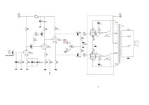
I’ll attach a schematic (left channel).
What I did in the meantime: I put back in the old tubes, that had been painstakingly measured and adjusted by the dealer’s tube expert (long retired) in 2006. I had not used the amp extensively during the years, so I assume they are not “run down” completely.
Adjusted bias (adjustments necessary to hit the little meters’ sweet spots from back then was quite different from the newer tubes).
With the old tubes, V4’s temperature is definitely colder than V1-3 (they seem closer in temperature now), for what it’s worth.
Will take your advice and try to find someone around here who’s able to do the measurements you suggested.
If there’s anything you want to add after seeing the schematic: feel free!
Attachments
Last edited:
You already have 8.2 ohm resistors in each cathode circuit.
Just measure the DC voltage across each resistor when warmed up.
The cathode current is the measured DC voltage divided by 8.2 ohms.
You cannot properly maintain a tube amplifier without a digital voltmeter.
Just measure the DC voltage across each resistor when warmed up.
The cathode current is the measured DC voltage divided by 8.2 ohms.
You cannot properly maintain a tube amplifier without a digital voltmeter.
huggygood,
Good Question!
It does have the negative feedback port (connection) . . . J3.
However, J3 is not connected to either the 2, or 4, or 8 Ohm taps of the output transformer secondary.
Chances are, that connection has already been made, but it is not shown on the schematic.
That would be [almost] global Negative Feedback around the output transformer. Almost Global, because it does not include the input stage.
I bet you were looking for some form of Global Negative Feedback, Right?
But, it is OK Even if J3 is not used, never fear . . .
There is Local Negative Feedback in the output stage.
Ultra Linear is Negative Feedback
Triode Wired EL34 Pentode is Negative Feedback.
Triode Wired is more negative feedback than Ultra Linear.
Ultra Linear Local negative feedback can range from at least as low as 25% to at least as high as 80%.
Triode Wired is 100% Local negative feedback.
Take your pick, Either Ultra Linear Or Triode Wired.
And Pentode Mode is 0% Local negative feedback.
Then there is the dominant high frequency pole of the 2nd stage: R14, R18, and C10 are negative feedback at the pole frequency, and for all frequencies higher than the pole.
True, most do not consider this to be negative feedback, because it does not work at mid and low frequencies.
But it actually is Local high frequency negative feedback.
Last but not least . . . the 2nd stage's cathode resistor, R18 is un-bypassed; that is Local negative feedback (degeneration).
These are some places to look for negative feedback.
Last edited:
Note: The switch in the schematic is incorrectly marked: it says triode mode, and pentode mode.
But it is actually triode mode, and ultra linear mode.
And, one switch is connected in triode mode, and the other switch is in ultra linear mode.
Check your schematics!
Attention to details!
But it is actually triode mode, and ultra linear mode.
And, one switch is connected in triode mode, and the other switch is in ultra linear mode.
Check your schematics!
Attention to details!
Guys - you really are amazing in your knowledge!
I’m just an end-user seeking help and I never got an official schematic for this amp (Unison Triode 20) - someone reverse engineered it by looking at the PCB and created this.
As for the switches: that’s what’s printed on the case, good to know, that there’s a difference.
If anyone can provide an official schematic (mine is missing the Phono-section anyway), I would be most thankful: then I can get the amp serviced.
That bias arrangement does both output tubes in one channel together. That would still require both tubes to be carefully matched. Also, if R53 and R54 are not carefully matched, as well as R55 and R56, that could lead to inequality of bias. It would be better if the two cathode resistors were matched as well. Alternately, if this amp had a way to bias each tube separately, the matching of parts would be less of an issue.
Buying a "matched quad", you are at the mercy of the person doing the matching, and how fastidious they are. I recently purchased a "matched quad" of Soviet-era 6∏6C (6P6S) from a dealer in Ukraine. These are 6V6GT equivalents, and they had the results from their tester drawn on the base of each tube. Those results were indeed closely matched, according to the tester use - 42/3.8, 42/3.7, 41/3.9, 41/3.8. (I'm assuming the first digit is the Gm rating on their tester, and the second in Gm in Siemens). When tested on my Hickok 800A upon arrival, Here are the Gm results I got, in order - 3650, 3925, 2750, 2700. Yes, different testers yield different results, but the relative results should be the same, or close to it, for them to be considered "matched".
rayma suggested swapping tubes, and I agree. If the temperature variations follow the tubes (after biasing), then the tubes are not well matched.
Assuming that V1 and V2 are the equivalent of V3 and V4 for the other stereo channel, then I would expect V1 and V4 to be similar in temperature, and lower than V2 and V3, which should also be similar to each other, but get less airflow from the outside. Is something impeding the airflow next to V1, or reflecting radiated heat back to it, maybe something sitting next to the amp?
Thanks again for giving advice and hints!
Airflow: the amp is freestanding, so reflections or different airflow should not be an issue.
So it all comes down to measure bias, as you all suggested. AFAIK for the Svetlana EL34 “winged C” I should settle for 35-37mA at 400V (393V), right?
I refrained from measuring voltage at the 8.2 Ohm (in my case, actually 2.7 Ohm!) cathode resistors. I do have a digital multimeter, but this measurement scares me, to be honest, working at an open tube amp…
But I’ll be able to get my hands on a “TAD Biasmaster”, that lets me do the measurements more safely using their tube socket adaptor probes.
In case you know the device, the online manual left me a bit confused about whether I can install all four probes at the same time and switch between them, or whether measurement can only be taken with ONE probe installed.
Quote: “This procedure [they refer to install only one probe instead of all 4] has also to be made in amplifiers that have a Cathode resistor ( like for example Mc Intosh MC30) . By installing more than one adaptor probe of the TAD Biasmaster chances are to make a faulty measurement”
The German manual is more specific: “…amplifiers, that have each one cathode resistor per tube or pair of tubes (like McIntosh MC30). Using two or more adapters at the same time might lead to errors in measurements.”
I looked up the schematic for the MC30 and I got even more confused, since I do not see a resistor at the cathode, only a direct wiring to the transformer.
So: What does that mean in my case? Can I install all 4 probes at the same time?
Last edited:
There is no reason to be scared measuring the cathode resistors. The voltage expected is below 1Volt.
If you are nervous for the voltages in the neighborhood i suggest you solder 4 wires to the resistors in case,
route these wires outside the amp together with a ground connector and connectes them to a
terminal . There you can measure the voltages and don't need to poke around inside the amp.
Using "biasmasters" is just another work for wasting money.
The Four 8.2 Ohm cathode resistors (or in your case the four 2.7 Ohm cathode resistors) all connect from their respective cathodes to ground.
The top plate of your amplifier has lots of "real estate" (room).
If the underside of your amplifier top plate has the room, you can drill 4 holes in the top plate.
Mount four Tip Sockets in the holes. Connect the four tip sockets to their respective cathodes.
Plug your meter Red + lead into one of the Tip Sockets. Connect the meter - lead to ground.
Measure the voltage. Repeat for the other three Tip Sockets. (You really need to get an inexpensive digital or analog meter).
Example:
If the cathode current is 37mA, and the cathode resistor is 2.7 Ohms, then 2.7 Ohms x 0.037A = 0.099V (about 0.1 volt, easily measured).
A slight in-accuracy of the Meter is OK. That meter has exactly the same accuracy or the same in-accuracy for all for Tip Sockets.
0.11V four times, or 0.98 Volts four times, who cares?
One important thing is that the voltage reading divided by 2.7 Ohms is approximately the current you want to run the tube(s) at.
Another important thing is that the voltage of one channel's push and pull tips are very well matched,
and the other channel's push and pull tips voltages are very well matched.
You should check this when the tubes are new.
It is a good idea to check again in a week, then 3 months, then a year.
The tubes either start matched, and age together, or they do not.
Un-matched? Then get better matched tubes.
Push Pull output transformers Hate Un-matched plate currents.
Low frequency saturation, distortion, and even intermodulation of the mid and high frequencies.
If you are scared to measure the low voltages on 4 cathode Tip Sockets, you need to stay away from vacuum tube amplifiers (and keep away from solid state amplifiers too).
I am Very sure you ARE up to the task.
Try Eurotubes.com Their matched tubes are MATCHED!
They do sell a number of JJ tube types, EL34 included.
Have fun!
Last edited:
The top plate of your amplifier has lots of "real estate" (room).
If the underside of your amplifier top plate has the room, you can drill 4 holes in the top plate.
Mount four Tip Sockets in the holes. Connect the four tip sockets to their respective cathodes.
Yes, this works well. As an example, I am rebuilding a few Heathkit W4-AM amplifiers. They don't have a bias control, but they do have a provision for balancing the current draw through the output tubes (These are mono amplifiers). The original way is a bit weird, so I will not mention it here. My solution was to drill holes, add tip jacks, and put a 1 Ohm resistor across each. In the case of the OP's amp, you will want to run wires to either side of the cathode resistors as described above. Here's the described installation in place on a W4-AM:
One end of each resistor will be directly connected to the cathode of each output tube, the other end will connect to a resistor network connected to that potentiometer. From the top, it looks like this:
BrassTeacher,
Because you used 1 Ohm between cathodes . . .
A good DMM is needed.
Most analog meters do not read that low.
I mV difference between cathode voltage, is 1 mA difference current.
Probably OK for most push pull output transformers.
5 mV difference between cathode voltage, is 5 mA difference current.
NOT good for some push pull output transformers.
Look at the graph on the last page of the Heathkit W-5M manual.
It shows the surprisingly large low frequency distortion with just a small amount of un-balanced quiescent DC push and pull currents . . .
Even though the Negative Feedback is being used (negative feedback makes saturation Worse).
How is this done?Of course, I did a proper bias setting (can be adjusted for each pair only)
All good fortune,
Chris
Chris Hornbeck,
I think you already know . . .
There is a single bias adjustment for one channel's push pull pair, and another single bias adjustment for the other channel's push pull pair.
That Requires a Very well matched push pull pair for each channel.
Set the current to 2X the cathode current you want for each tube of a channel.
Then repeat all of that for the other channel, using its single bias adjustment.
I always use Very well matched pairs of JJ tubes for my push pull mono-blocks.
I get them at Eurotubes.com
I drive over and pick them up (lucky me).
By the way, the Heathkit W-5M mono-block has a pretty good bias and balance setup; although I do not use anything that complex in my mono-blocks.
Have fun!
- Home
- Amplifiers
- Tubes / Valves
- EL34 Push-Pull: big temperature differences between the 4 tubes - problematic?