Good software for designing active elliptic reconstruction filters?

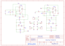
I have been looking to design an active elliptic filter for a dac project that I have been working on to speed up audio at a specified multiplier. The dac can speed 44.1 audio all the way up mhz sample rate ranges. I was wondering if anyone can recommend a tool to help design an active elliptic reconstruction filter?

Previously I have attempted to implement a passive elliptic filter stage using the rf-tools elliptic filter calculator but struggled with the very specific inductor and capacitor values required for said filter. Implementing a passive filter multiple times as required for the project would be a complex undertaking so I'm thinking an active stage would be easier to implement and also be more repeatable when needed? If my target sample rate was 2.8224 mhz images will start appearing at around half of the sample rate so I'm guessing a filter utilising a 1.3mhz cut off would be sufficient to suppress the dac images? My maximum theoretical frequency would be around 1.28mhz. If anyone has any pointers I am eager to listen.

Crown IC150 Phono Stage

Someone asked me how I fit the Jung-Didden regulators into this box...which led me to look at the phono section.

The two input transistors that Crown used, 2N3895A and PN4250A low Rb, the LM301A opamp is truly ancient. I hadn't seen this type of phono-pre, but only started seriously dabbling in phono pre and RIAA comp networks in the past decade or so!

SY isn't around to throw bricks at this Crown design. The compliance, in simulation, to the RIAA curve is very good. Will have to see if my actual living model is equal to the simulations.

Attachments

  • Crown IC150 Phono Compliance.png
    Crown IC150 Phono Compliance.png
    5.7 KB · Views: 263
  • Crown IC150 Phono Section.png
    Crown IC150 Phono Section.png
    13.9 KB · Views: 311

SiC JFET, Maybe the Best Choice of Depletion FETs

Looking through a lot of relatively new circuit designs of valve amplifiers, the Constant Current Source takes almost all the leading position. Except those used in Filament CCS, almost all other designs are Cascode ones.
1658228003048.png

For example like this, the M3 and J1-J4 formed a Cascode CCS.
If we set it at 10mA and using DN2540 at M3, the FET at J1-J4 position could only get a Vds even below 1.5Volts, which can't drive the FETs into saturation area.
If the lower side FET can't go into saturation area, how could it deliver a constant current?

These new SiC JFETs entirely eliminated such problem. The Vgsoff of these transistors is typically -9Volts, which means you'll have over 8Volts for the lower side.
I could say these SiC JFETs fully "liberate" the lower side conponents, providing a better working condition(Over 8.7Volts for 25mA) comparing with traditional Depletion MOSFETs such as DN2540(lower than 1Volts for 25mA) and IXCP10M90S(About 2.4Volts for 25mA). Even LM317 could be used here for a higher current accuracy.

I've bought some samples of the 650V 80mΩ version, and give it to my friend replacing DN2540 in the Mu Follower design. Now his only remainging question is what to use at the lower side😀.

The problems of the SiC JFETs are also clear.
The capacitance is the biggest one. The Rdson=80mΩ version has a Crss of 88pF, while the Crss of Rdson=400mΩ version is 18pF. It's much higher comparing with DN2540.
Maybe packaging the UJ3N1701K2 is the ultimate solution 😵

UJ3N0650.png

Here's the curves I traced with DTT-X of UJ3N065080K3S.
image2.png

400mR.png

These two are the characteristics of UJ3N170400B7S.

And I also managed to trace the output characteristics in high voltage area of UJ3N065080K3S with etracer. Since it's not easy setting, I've only scanned the curves when Vgs=-9.0V.
Notice that Vgs should be provided externally and previously, because the normally-on state of JFETs will trigger the Short Circuit Detection of etracer.
It's not as horizontal as DN2540, so Cascode is necessary.
1658230986703.png

Dayton BR-1 original or modified by Dennis Murphy

Hello everyone. I'm thinking of building a pair of Dayton BR-1 speakers.
I would be interested in your opinion on whether to do it with your original crossover or with the crossover modification proposed by Dennis Murphy.
The drawer would have the measurements of Paul Carmody's Classic II.
The position of the drivers would be respected according to the original BR-1.
The duct would be later.
Another question is if the tweeter in Murphy's crossover mod is the Dayton DC28F-8 or does he have another.
First is original and second is Murphy.

http://murphyblaster.com/content.php?f=pe_br1.html

Attachments

  • BR-1_diagram_02.jpg
    BR-1_diagram_02.jpg
    13.7 KB · Views: 328
  • woofer + tweeter circuit.JPG
    woofer + tweeter circuit.JPG
    12.9 KB · Views: 293

KEF 103.4 mid-range driver problem (B160 SP1278)

Hello everyone,

I just bought a pair of old KEF 103.4 speakers from the 90s. Unfortunately 1 of the speaker sounds completely muffled. I thought the ferrofluid of the tweeter had to be replaced but the problem seems to be the mid range driver. The driver is a b160 sp1278 and it seems that the membrane is somewhat stuck. if I apply pressure on the membrane it does not move freely. It feels like there is a lot of resistance (the other speaker’s membrane is much more flexible and the speaker sounds fine). It also seems there there is a damage. I attach a video where I try to visualise the issue Login to view embedded media
I would swap out the driver but I am not able to find any. Does anyone have a clue if there is a way to fix this issue? Any suggestion is highly appreciated. I really don’t want the speaker to end up in the landfill so I would like to repair it.

Many thanks!

Alberto

TSE-II build and arcing rectifiers (mostly 5AR4 vacuum tubes, new issue)

At the request of those who are helping me with this issue, and for the benefit of all members of the community who may someday experience a similar problem, I am going to gather the details of this "case" in this new thread...

The circuit in question is the TSE-II SE amplifier with 5842 input tubes and 300B power tubes.

The schematic is attached to this post.

The power transformer in this case is:

https://edcorusa.com/products/xpwr178-660v330-0-330-200ma-6-3v3-15-0-3-15-6a-5v2-5-0-2-5-3a

I measured DCR as follows:

  • Primary winding: 1.75 ohm
  • HV secondary: 35.3 ohm and 36.8 ohm

I did use this choke in place of R4:

https://edcorusa.com/products/cxc125-10h-200ma-10h-200ma-choke

Its DCR is 75 ohm (vs. the 150 ohm R4).

C4 is a quality 47uF 450V electrolytic capacitor.

(A 5AR4 should be able to handle a 60uF input capacitor, according to the datasheet.)

C5 is a quality 150uF 450V electrolytic capacitor.

I have the following motor run capacitor in parallel with C5:

https://www.digikey.com/en/products/detail/kemet/C870CG36100AA0J/6556371
(100 uF Film Capacitor 470V Polypropylene)

Attachments

3 way design help TPL 200Hh TD10M TD15H+

hello everyone
I have a speaker in the works that I’d like some input for
Im quite new to diy so it’s quite a ambitious project
The driver I have are
Beyma tpl 200h
Ae td10m 4ohm ( on order )
Ae td15h+ 4 ohm

The front end will be mini dsp flex so it will be a active speaker
I’m planing on using 3 pairs of stereo audiphonics Hypex ncore amps

The main problem for me is the size, I want to keep it as compact as possible

I was thinking of either having the 15s in there own chamber maybe sealed
And then either having the tdm and Tpl share a chamber
But I could also remove the rear of the tpl so that would need it’s own chamber

I was either thinking of having the speaker 12” wide for the td10m, so it looks slimmer from the front
And have the the cabinet 17” deep for the 15” drivers to be side firing

Or have it 17” wide and the 15” face mounted but make the speaker 12/13” deep

So sealed or ported for the td10m / 15h+
At the minute the td15h+ are in small sealed boxes with about 750w each to them

I was thinking of being able to get around 60 litres sealed in the 3 way

John recommended ported for the td10m

The other thing I’d like to do is cross the td10m as low as possible to the td15h+ with some shallow slopes to help that 100hz area

Help Sizes slopes stuffing cabinet design etc would all be appreciated

Thanks in advance

New owner of Beveridge Electrostatics!

Hi all-

I am excited to report I have finally found and purchased a pair of Beveridge electrostatic speakers. I am NOT excited to report they are in rough shape and do not currently run; they need significant work. So let's start a conversation, shall we? I'm happy to hear from anyone who's been there and done that.

They are model 2SW-1 but the separate woofers are gone. The amps need a significant amount of work, time & money to fix. Before I do all that I first want to verify the health of the ESL elements, to the extent possible anyway. So let's start with them.

I have not opened the cabinets yet but the capacitance measured at the banana plugs is ~2,500pF from stator-to-stator, and it's one-half that from the membrane to any stator (~1,300pF). Both cabinets measure the same; I take that as a hopeful sign.

So... what do you think? What testing and inspections should I be doing here? Any input is most welcome, these are unique in many ways and I could easily be missing some important detail (or several 😀).

Many thanks.

Fender Transformers

I have a shelf of old Fender transformers. Some are from the Fender/Panasonic collaboration many years ago (they made power amps and larger scale mixing consoles). Some are older transformers for tube amps. Small ones are probably for reverb tanks? Most of these are NOS (new old stock).

I'm moving and these need to go, hopefully to a good home. Contact me if you're interested in any of this.

Location: Chicagoland Illinois USA

Additional pics.
https://www.teedy.audiovidual.com/s...606f7b7e/c69fe0e0-b976-4675-8937-313180f0d5cf


e2db5cfaded1409c8c098b2b9dd5bc7e.jpg

For sale Icepower 50ASX2BTL PCB and various other amp Ghent Audio parts.

Im parting out my Icepower 50asx2BTL mono blocks.
I have 2 Modules available, real BTL not SE converted. ASKING 75 SHIPPED EACH USA
Ghent Audio MonoBlock case 60 shipped Like new still
Ghent Audio RTX Module have 2 of these as well. 65 shipped COnt USA.

Attachments

  • IMG_9266.JPG
    IMG_9266.JPG
    591.9 KB · Views: 73
  • IMG_9267.JPG
    IMG_9267.JPG
    559.1 KB · Views: 65
  • IMG_9274.JPG
    IMG_9274.JPG
    298.1 KB · Views: 58
  • IMG_9273.jpg
    IMG_9273.jpg
    265.6 KB · Views: 56
  • IMG_9272.jpg
    IMG_9272.jpg
    312.5 KB · Views: 89
  • IMG_9271.jpg
    IMG_9271.jpg
    574.6 KB · Views: 62
  • IMG_9270.JPG
    IMG_9270.JPG
    397.5 KB · Views: 68
  • IMG_9268.JPG
    IMG_9268.JPG
    420 KB · Views: 64

Fostex version 2.0 software

hello, i picked up a fostex vf80 recorder from reverb.com,not knowing it didn't have the build in CD burner ,so i found one CD 1-a burner on eBay,installed it in the unit,and found out it was not plug and play, you have to upgrade the software as well, the software is fostex version 2.0,i know this is a shot in the dark,but if anyone happen to have a fostex version 2.0 for fostex vf80 recorder,and can put it on a flash drive/cd i am willing to pay for it as well as shipping,this maybe a long shot,but without the software the installed CD burner wont work,thanks

Budget bookshelf speakers build recommendations?

Hey everyone!

First time posting here. I have owned and used a pair of KRK Rokit Classic 5s for close to 8 years now. I always really enjoyed their sounds, not knowing any better. It has 'good enough bass extension' and sounds alright.

I have been meaning to upgrade my system for a little while know. I would like to go the DIY road because I want the absolute best bang for my bucks. I have some experience when it comes to DIY, enough to undertake a nice build, going slow and steady.

I'm somewhat on a tight-ish budget, and wanted to explore my options. The speakers would be placed in a room that is about 14/16 square meters, on bookshelves.

I listen to jazz and electronic music mainly so bass extension and good detail retrieval is important for me. Most of all, I'd like for the build to truly feel like an upgrade from my current studio monitors.

I have about 400€ set aside for the build. I've been looking everywhere but it's hard finding good, recent recommendations, and I always end up clicking on dead links or seeing recs from 2011. I was wondering where the best value lies nowadays.

I don't mind sourcing individual parts vs. getting a kit. I have access to some woodworking equipment but would prefer something straightforward vs. some odd, complex slanted cabinets. Of course, if a complex cabinet is what's standing between me and an awesome speaker, I'd be willing to go the extra mile.

I would chose an amp based of my choice of build. Budget for that is around 200/250€. DIY is alright as well.

6SN7 push pull flea amplifier project

Finally got a few hours to lash together a design I've been playing with, and I am extremely proud of how it turned out. The very messy prototype is surprisingly hum free, and can be driven to 1.4w clip, but can sustain a clean 1.2w continuously, using a ~300 volt supply. My calculations point to around 2w would be possible at higher voltage around 400 or so without too much change.

Now here's the goofy parts- I am using Antek toroidal power transformers as outputs, and due to the low current and power, 10VA units work great, and are very affordable. In order to keep the current balanced, I'm using the garter bias arrangement, which works way better than you think it should, and at such low current and voltage is not a big loss at all having extra cathode resistors. I drop 9.2 volts across each 1k resistor, so my tubes are running at 282 volts, sitting at around 2.6w idle dissipation per triode, 5.2w per tube, not counting the heater. It's got NFB too, just to make everyone upset 😀

Here's a messy teaser pic of the first rig, but I'll get up a schematic soon. I've got an aluminum box coming tomorrow and will work on a layout for it too.

Attachments

  • IMG_20170215_191054.jpg
    IMG_20170215_191054.jpg
    969.6 KB · Views: 11,096

Need amplifier tester - NE FL/SE Georgia

Hi,

I have three tube amplifiers including two kits recently constructed (one of them still in progress actually). I'm looking for someone in Northeast Florida or Central Florida or Southeast Georgia who can spend a few hours one afternoon with me putting them on a 'scope for testing. I'll drive them to you. I haven't touched a 'scope in over 30 years and don't have access to one. Even if I did, I'm not qualified.

Anyone within a few hours of driving available for some quick tests?

Thanks!

Is this amp safe to power up with output transistors removed? (Luxman LX-104)

Amateur level status person here...

Just picked up a non-working Luxman LX-104 stuck in protection.

Have verified that it will come out of protection if I disconnect R channel from protection board.
Found negative rail voltage floating on output of R channel (present on Base and Emitter of all outputs of R, but not L channel).
Pulled R channel outputs and tested on a cheap and cheerful small ebay component tester. All seem to test fine.
No fuses blown and current draw at rail fuses is nominal.
Have done an in-circuit test of all other small signal transistors and have found no shorts. But, I can't really access the ones on the "Main Drive" daughter boards as seen in the attached schematic.

So I thought, if it's possible, that I would like to power it up (even at 1/4 or 1/2 power via Variac) with the outputs removed to run some left to right channel voltage comparisons to see if I could identify where the errant voltage is coming from?

There is I assume also the possibility that the outputs are faulty and just not showing the fault at low voltage? And if this is the case I should see no voltage at the B and E pads with the outputs removed?

So, can someone tell me if the amp can be powered up sans outputs?
Or so I need to solder in some temp components to make it stable?

Thanks in advance.

PS, the numbers in red are the voltages I took when I realized what was going on.
Q514 is a 2sc1845 also attached to the heatsink near the outputs.

Luxman voltages.png

Old guy returning and need some advice on a 1624T Supro amp build

I have been away from the tube amp world for a few years. I am going to build a 1624T Supro syle amp with 12AX7 pres and EL84 power tubes. The amps were built using 6973 which I can get NOS but pretty costly, around $100 each. Am I making a mistake by using EL84s?
I have in mind to use a vintage greenback 12" speaker which is 8 ohms. I also have a Webber alnico 12" I could try also.

Two questions.
Is there any good reason to use the typical 5Y3 or can I just use diodes?

Do you have any recomendations for the PT and OT?

I will keep one hand in my pocket...lol

Billy

  • Locked
Bose 802

I have a pair of bose 802 unloaded cabs and would like to fit some large speakers in. I have already cut the baffle out on one and ready to fit a new plywood baffle. The question is 2x10 would be my prefered choice but it would be a real tight fit, but possible or 1x10 or 2x8 thoughts please. I do have a pair of subs so bottom end isnt everything.

NOS DAC chips still in production

Hi everyone,

Does anyone has an updated list of NOS DAC ICs that are currently in production and are not sigma-delta?

The ones that I am aware about are:
PCM56U
AD1851RZ
AD1856RZ
AD1866RZ
I can't find PCM56 chips of the K and J version and devices from AD in the J version.

I'm currently testing an AD1866RZ and it sounds much better than most consumer audio equipment sigma-delta DACs. I can't describe, but for me multibit NOS DACs seem to sound more detailed and natural than sigma-delta, specially in the lower and higher frequencies, but this is only my opinion, in fact most newer OS DACs clearly outperform resistor ladder DACs in terms of measured specifications, maybe I have some hearing or psychoacustic problem(s).

Well going back to the NOS chips, which one from this list sounds the best? I'm more inclined to give the PCM56U a try, maybe in current output configuration? What do you think? 🤔
The PCM56 needs a deglitcher? Or is it only required for single chip stereo applications?
Any suggestions?
The PCM56U sounds better than the AD1866?

All the Best,
Danny

DAS: Which RAID Configuration to Minimize Bit Rot Error Risk?

I'm dangerously overdue for a revamped back up system; I just use old JBOD among two xeon PCs, though both have ECC RAM. I'm so badly overdue for new storage hardware it's terrifying!!!! But I've got to be sure to buy what I need most to protect my data.

Capacity wise, total data is ~ 350 gig, but I will eventually want to not only do hundreds more uncompressed CD track rips but also dozens rips of TV episodes and rare movies from DVDs (though rarely from not BDs). Those videos I'd be saving as MKV files, not much larger ISO files. The good news is that I mostly watch (re-watch) lots of vintage stuff, and when I do buy more movies I do so on BDs, which are less likely than DVDs to get hit with bit rot. Thus, I'd be less inclined to rip (with RedFox) and back them up. So for for these back ups, should each RAIDed HDD drive be 5 or 7TB?

My plan is to have a multi drive DAS in my living room and bedroom. My internet connection is via my iPhone's wifi so I have no router that could have been otherwise used with two NAS instead. So for every monthly backup session, I'd have to grab the bedroom DAS, bring it to the living room DAS and use my PC's Windows Explorer to share and/or update any document, videos, music files between them via USB.

But got to make sure I don't trip during trips! It would have helped if at least Qnap or Synology made at least one DAS with a safety handle! Why not a case like this? https://www.silverstonetek.com/en/product/info/server-nas/CS01-HS/

AND how best to protect data from however unlikely bit errors?? My data is my life. Qnap and Synology use btrfs, zfs or other non-Windows file management systems offering powerful bit error prevention and self-healing between RAIDed drives. But the learning curves of those file systems-let alone the initial building of them-are way more for the enthusiasts than newbie laypeople like me, and I don't want to get stuck with hardware/software that's a nuisance to learn, use and maintain.

Instead, will the right RAID configuration in both DAS boxes and the ECC RAM in both my PCs get me reasonably good error prevention? If yes, which RAID config to use with two to four 5TB or 7 TB HDDs in each DAS? https://www.seagate.com/products/hard-drives/barracuda-hard-drive/

And which Qnap or Synology model DAS?

B1 rev 2 board for sale

B1 rev.2 complementary FET, as discussed here :
https://www.diyaudio.com/community/threads/b1-rev-2.301812/

Board is designed by member Mikerodrig27, as posted here in the thread:
https://www.diyaudio.com/community/threads/b1-rev-2.301812/page-20#post-7266237

Resistors are Vishay CT55, Dale CMF60, Dale RN60 in the critical position. 2SK170/2SJ74 matched (to 0.1mA) quad IDSS value 8.3mA, from the highly recommended punkydawg ( eBay seller). Trimmed to a rock steady 0.00V dc on my Fluke multimeter on 300mV range.

58 USD (shipping included, registered + tracking). Shipping from Singapore

AD1862 DAC Chips for sale

A quad of AD1862N-J chips for sale at xx USD ,shipping ( registered + tracking ) is included.
This quad belongs to a friend who bought too many of these chips together with me. We built the Miro AD1862 dac together .
We have no spares anymore after these are gone. They are clean, new.

Paypal FF only please. Check all my past sales records for reference. All buyers know i pack very well and provide proper updates.
Shipping from Singapore.
  • Like
Reactions: miro1360

Need help simulating quasi saturation for emitter follower in LTSpice

Hello all,

I am still learning about BJTs principle of operation and came by the concept of quasi saturation and hard saturation.
To better understand the concept I tried simulating emitter follower using popular transistor models.
I am not sure at what I am looking, but would appreciate if someone can explain.
I tried varying collector current of Q1 by changing R2 from 100R to 1K.
Probed collector current of the Q1 and I get kind of wobbly sine wave.

Sim file is in the attachment.

Attachments

  • t-sat.PNG
    t-sat.PNG
    11.5 KB · Views: 95
  • Draft4.asc
    Draft4.asc
    2.4 KB · Views: 50

What if the computer virus had AI?

It gets worse:

"The malware uses artificial intelligence to make informed decisions and synthesize its capabilities as needed to conduct cyberattacks and continuously morph to avoid detection."

[..]

Using the current early versions of generative AI, EyeSpy is capable of:
  1. Selecting its intended victim independently or through a threat actor’s specification.
  2. Assessing the target environment, platform, applications and environmental footprint.
  3. Identifying optimal vectors to extract information.
  4. Writing malware on the fly – for example, if a target is on a specific video conference app, it will compose, test and validate the malware for that app.
  5. Executing the attack.
  6. Analyzing the QA result.
  7. Self-repair and continued attack iteration until it has achieved the attacker’s goals.
Jan

Favorite Composite Power IC for Headphone Drive?

Hive Mind,

What's your favorite 2nd-stage (power) IC for headphone drive (to 16 ohms) in a composite circuit? Will likely use the use the OPA1611 as a first-stage in the composite. The power IC should have at least +/-250mA of drive current and at least +/-12V rails. I want a composite design in order to get super low THD and noise.

I've not checked lead-times, but these are the candidates I've found that meet my criteria, so far.

OPA551
OPA564
LME49600
(this one looks great, and I've had good sonic experience with the old LME National parts, and it won't need as much FB compensation)
TPA6120 (ditto)
BUF634


Another approach would be to parallel some high-performance opamps for 250mA performance. The performance of these opamps is so dang good that I wouldn't need a composite solution. I'm looking at these:

OPA1655 (x3 in parallel)
OPA1622
(x2 in parallel)

Appreciate your time.

DD

Perreaux PMF2150B Restoration

I picked up a Perreaux 2150B and working on restoration. Someone desoldered the wires from the Bridging switch to the boards.

I have the service manual, but this wiring is not well detailed. All the photos I can find are from top side of the boards.
I believe the wires go where the inputs attach, but I want to be sure. Hoping someone here may have knowledge of these amplifiers.
If I had photos from the underside, it would be easy to figure out quickly.

Thanks.

VC2002 function generator service manual or calibration

I just bought a simple Victor VC2002 generator. It works but the Voltage display seems to be fully out of range. On the front panel it says Vp-p but actually it measures something half of p-p , so a Vmax. But even this value is about 20% wrong. I found an older post with a link to the schematics here (downloadable from Scribd). Unfortunately, the quality is so bad, that I can not identify anything. Does anyone have a better schematics? Or can tell me, which potentiometer is responsible for calibration of the voltage display value?

Experiment with 12AU7 pre stage + CSS servo

Hi all,
Here is schematic of my 12au7 pre, it use dual polar hv and an opamp to sense the output node and output current through 2 current mirror (q1,q2 and q7, q8) to set dc offset at output voltage.
You may ask why i make thing so complicated, instead of cap at the input, it can be moved to output so i can get rid of negative hv and opamp servo. But my next stage can have input impedance as low as 10k (common pot value) so i can't use low value capacitor. I want to use capacitor as low as 0.01uf so i can afford hi-end Duelund cap at that position.
With this schematic, it simulate perfectly 0V at output but when i try to change R1 and R19 different value instead of 300R, it no longer work correct, output jump between supplies.
Does anyone have an idea of what's wrong here? Thanks!
12au7 pre + css servo.jpg

Attachments

PCM63P and free empty dac board

SOLD SOLD
One pair of PCM63P chips, with free Miro PCM63 DAC board ( blank)
Circuit design and board info available here:
https://www.diyaudio.com/community/...s-input-nos-r-2r.354078/page-209#post-7049224

The PCM63P chips are bought new. Please refer to pics attached below.

Price is $110USD, covering also the registered shipping worldwide from Singapore.
I have sold and delivered almost 20 items successfully to Europe, UK and US with zero problems.
My preferred transaction would be PAYPAL FF only. For members who are unable accept this mode of payment would have to skip this deal, i am sorry.

I will always be happy to buy Miro a coffee as usual, for his generous sharing.

Help selecting mid bass driver replacements

Hi
I'm a complete novice when it comes to this stuff so go easy on the nooB!

Speakers: Mission m64i
Problem: one blown mid bass driver LF-M049, 8ohm, 168mm OD, 140mm cutout.

I am having great difficulty finding a replacement because the baffle cutout diameter is 140mm, which is slightly too small for the normal 6.5" driver options. There's no info available for this driver using the search term LF-M049 as per the sticker on the magnet. It looks just like a regular Monacor driver, but they don't have one that's the right size for the baffle cutout.

However I've found a Peerless driver - SBS-160F35AL01-04 - this fits but I don't know if it is the right spec.

What sensitivity should I be using? Most of the woofers seem to be around 84-09 dB but these Peerless ones are 78.7 dB. So I haven't the foggiest if they would sound ok and match the crossovers.

Like I day - completely ignorant about this stuff! But am an engineer (mech) and love getting into new stuff, so feel free to educate me.

Any guidance on what to go for in terms of audio specs would be greatly appreciated. I'd replace both drivers obviously.

Amp is a Cyrus III with PSX.

Old Preamp

Hi ... I have a Goldmund VSR-V2 preamp. Spec sheet says output stage impedance < 10 ohms and corrected output impedance ~ 330 ohms.
I'll be driving an advertised total 2012 ohm load not including any added residual load which might be substantial as it will be driving 6 amplifiers, but are all short IC's.
If 10 ohm I should be Ok. Not sure what to do if it will not take load.
Would appreciate you guys help.
Zene

ACA mini amp supercap question

Second thread from the novice ACA Mini builder.

This time I have a question about the supercaps for positions C6. The BOM says "SUPERCAP 1F, 2.7V OR GREATER". My Completion Kit has two blue caps labeled "2.7V3.3F". [See photo.] Are these OK? Does the "OR GREATER" refer to the capacitance? I don't want to solder these in until I know.

IMG_20230803_153647500.jpg


I read that film capacitors have no polarity, so I assume I can solder these red ones (1 uF) into C1 without worrying about their orientation.

IMG_20230803_153734488.jpg


Finally, a progress report. My new soldering iron is working well, and I've got the board to the stage you can see below. I learned how to desolder after I noticed that the small transistors don't face the same way for the left and right channels. I just assumed, wrongly, that they'd be symmetrical.

IMG_20230803_153530068.jpg


I am having loads of fun with this project. If it works and sounds good when I'm all done, I'll be grinning from ear to ear!

Aiyima STK433-260 board - PSU questions

https://en.aliexpress.com/item/1005001302655864.html
Hello. Not so long ago I received this board I bought without being entirely sure whether I'd be able to power it properly or not. I was attracted by it's price, power and neatness of the PCB. I knew that I would need a dual AC power supply (2 AC waveforms with a 180 degree phase shift) and assumed that I'd somehow manage to power it using two of my transformers. Well, it seems that I won't be able to use one of them since the rectified voltage that I would get from it after rectifying and smoothing exceeds 50V, which is way beyond the maximum value the STK chip supports (max. +- 40V min +- 30V). The other transformer, on the other hand, has a secondary providing 28v. The rectified and smoothed DC voltage would be approximately 38.4 V assuming a voltage drop of 0.6V of each diode in the rectifying bridge. (28/0.707 - 2*0.6) The seller/designer recommends +- 37V. I intend to get +- 38.4 V from a single secondary.
Here are my questions:
Has anyone managed to successfully power this kind of Sanyo chips (STK family) using a transformer with a single secondary?
Would it greatly impact it's performance in a negative way?
Would it actually present some danger to the speakers?

Building the TPA3116

Hey guys, I wondered if anyone could give me any tips or insights of what've done so far. I need to know the following:
1- Is there anything wrong with my circuit?
2- How to connect XL60? Pin 3 and 6 together? Only pin 3? Or only pin 6?
([Warn] : Found some components Pins floating, suggest placing No Connect Flag on the Pins : U2.2,U2.6,U3.2,U3.6)
3- Wanted as well to know, recommended Power Rating for the Resistors
4- PCB Design: Anything I should have done in a different manner?

Thanks in advance
1691093842313.png

Attachments

  • SCH_Schematic1_1-MAIN_2023-08-03.png
    SCH_Schematic1_1-MAIN_2023-08-03.png
    30.2 KB · Views: 151
  • SCH_Schematic1_2-PS, IN, OUT, V+_2023-08-03.png
    SCH_Schematic1_2-PS, IN, OUT, V+_2023-08-03.png
    28.1 KB · Views: 148

What distortion do you emphasize/remove when tuning a tube amp?

Odd question but I'm hoping someone may have experience to guide my tuning.

I've built a set of EL34 monoblocks which I'm steadily refining, mainly tuning the feedback for best response and the input stages for optimum values per the loadlines. By the book I'm aiming for minimum distortion across the board. OK cool, makes sense... but it sucks some of the magic out of the soundstage depth and width.

Does it sound better, objectively? Yes. Does it sound better subjectively? Ehhh... I'd like to get a better balance between the frequency response and pleasant room-filling depth you get when it's close but not quite right.

Detail, tone, and extension in high and low is fairly consistent so I'm happy with that, now I'm just fine tuning the final character - which is mainly the imaging and holographic qualities.

So the question is: rather than chasing minimum distortion in all categories, which distortion should we "allow" or focus on? We all hear about the even harmonics being the "good" ones, so do I allow a few % of 2nd on my loadline calcs? 4th? Etc.

My first iteration was poorly optimized for the output load, had too much feedback, was borderline unstable, and was cathode biased- but had some impressive depth when listening. I'm trying to get it back to that depth but without the faults.

Acoustic elegance TD15H+ Apollo

I have for sale two td15h+ Apollo subwoofers/mid bass there in gloss black 17” cubes made from 25mm mdf stuffed with lambs wool to give a a of roughly .6
They also come with a inuke 3000 with silent fan mod which gives them roughly 750w each

The cabinets have a nice finish but have a few chips and scratches from kids
The chips I’m sure can be touched up with some
Gloss black touch up paint to look great in the room again
Binding posts are on the bottom so they can face the room or the wall

They also come with grills but the lugs have been snapped off I can supply new lugs but they need the old lugs to be drilled out and new ones glued in again

These are super clean 15” that can play up to 500hz easy so amazing for music
Can be put in bigger enclosures or eqd in these small enclosures which are nice and compact

( note one driver has a earlier foam surround the other has a neoprene surround as bought at different times this doesn’t effect bass frequencies )

£700 for the pair with inuke

There heavy so collection only from post code TW17 shepperton U.K.
unless you want to arrange a pallet or something

Attachments

  • 25610FFD-985C-4BBE-AFD0-74041260F358.jpeg
    25610FFD-985C-4BBE-AFD0-74041260F358.jpeg
    598.2 KB · Views: 99
  • 1DCFA961-8256-44BF-A8E4-C4BA3979269C.jpeg
    1DCFA961-8256-44BF-A8E4-C4BA3979269C.jpeg
    499 KB · Views: 92
  • 84647FD3-81DD-4391-9583-576E6AD4C469.jpeg
    84647FD3-81DD-4391-9583-576E6AD4C469.jpeg
    496 KB · Views: 100
  • DDB61758-6A91-473B-8807-D3AE6D1F358D.jpeg
    DDB61758-6A91-473B-8807-D3AE6D1F358D.jpeg
    539.5 KB · Views: 88
  • 5FD48C08-DD8E-45F3-943B-225B11A8BEE6.jpeg
    5FD48C08-DD8E-45F3-943B-225B11A8BEE6.jpeg
    414.3 KB · Views: 90
  • 4FDCEE2A-9DFF-4468-A2C5-20984D60A5EE.jpeg
    4FDCEE2A-9DFF-4468-A2C5-20984D60A5EE.jpeg
    489.2 KB · Views: 73
  • 25B00E9F-0DDD-4CE9-87F9-F206DA395523.jpeg
    25B00E9F-0DDD-4CE9-87F9-F206DA395523.jpeg
    250.1 KB · Views: 75
  • A293BB9C-038E-40F4-8D8B-E00568B54228.jpeg
    A293BB9C-038E-40F4-8D8B-E00568B54228.jpeg
    453.2 KB · Views: 76
  • E4C8E1DC-6843-457A-9A09-D582339A6B3E.jpeg
    E4C8E1DC-6843-457A-9A09-D582339A6B3E.jpeg
    460.3 KB · Views: 78
  • 546F267A-7E73-40EB-AC75-CB526AE801E9.jpeg
    546F267A-7E73-40EB-AC75-CB526AE801E9.jpeg
    420.2 KB · Views: 82
  • 7300E872-6891-4AF5-857E-75AED982A401.jpeg
    7300E872-6891-4AF5-857E-75AED982A401.jpeg
    560.1 KB · Views: 83
  • 5ED76B34-3FEB-4C73-8840-E9ED780A8F8E.jpeg
    5ED76B34-3FEB-4C73-8840-E9ED780A8F8E.jpeg
    417.7 KB · Views: 92
  • Like
Reactions: Arez

Miro PCM63P NOS Dac sale

SOLD SOLD SOLD

Spare set of Miro PCM63 DAC for sale. i2s inputs on board.
Circuit design and board info available here:
https://www.diyaudio.com/community/...s-input-nos-r-2r.354078/page-209#post-7049224
You need a PSU and I2s source and a pair of single op amp for this DAC to function. Look at the info in the thread to see the PSU requirements.

Board fully populated with good quality caps eg. Panasonic FC for digital , Nichicon Fine Gold for all the analog circuit, Kemet ceramic bypass smd for the glue logic chips, Epcos film bypass caps for all the decoupling electrolytics , low noise non-magnetic resistors, good quality Nextron IC sockets etc. Packed with good parts.

The PCM63P chips are bought new for this project and used for a few months for this board. I have attached the pics of the chips when it arrived to show the legs before i inserted them onto the board. Pins of new chips need to be bent inward slightly in order be socketed, which i hope the pic can show (i am not great at taking pics).

Again, to remind you that I will not be providing the IV op amp.

Price is $180USD, covering also the registered shipping worldwide from Singapore.
I have sold and delivered almost 20 items successfully to Europe, UK and US with zero problems.
My preferred transaction would be PAYPAL FF only. For members who are unable accept this mode of payment would have to skip this deal, i am sorry.

I will always be happy to buy Miro a coffee as usual, for his generous sharing.

Atoll CD200- strange noise

Hello everyone!
I have CD player ATOLL CD 200 first generation. The player is upgrated with better capacitors, sockets etc. I bought it like this from Germany.
The sound is beautiful, the job is very well done. It outperforms the new Atoll CD200 signature.
Unfortunately few days ago a strange noise appear in the right channel. The left channel is clean.The quality of the sound is not affected in any way, but in the low passages of the music the noise can be heard,
Here is a link where it can be heard :

Login to view embedded media
I connected external DAC to the coaxial exit. Everything works fine, no noise.
I need help where might be the problem.

Channel imbalance with adjustable input level gain stage

Hi all,

I have a bit of a head scratcher with channel tracking and the attached, very simple circuit.

I have an issue with a low input level of the DAC I use for my TV and made a very simple gainstage based on a standard OPAMP non-inverting circuit. It works very well, gain is at x3 (9db). This then goes into an ESP P97 preamp as indicated.

The problem I have is that there is a large channel imbalance when using the pot to adjust the level, but, when the pot is at max (zero resistance), the channels are perfectly balanced. So, perfect balance with no resistance, imbalance with any other setting.

I did speak with Rod at ESP and he stated it must be the load resistors are not matched, everything else being rulled out as the channels are balanced with no resistance (i.e. max setting). But, they are matched?

I thought to ask you guys here, I ask Rod too many questions (!)

Attachments

  • 20230804_090850.jpg
    20230804_090850.jpg
    162.7 KB · Views: 76

FS: DIY Sony VFET R0 push pull vfet amp kits from papa Pass (2016 version)

FS: A pair of the 2016 First Watt push pull Sony Vfet amp kits. The pairs of 2SK82 and 2SJ28 are matched and graded by papa himself, all 4 are KE-33 rank.


(from the pdf) - The amplifier delivers 15 watts into 8 ohms and 20 watts into 4 ohms. The open loop gain is about 36 dB without a load, and 35 dB with an 8 ohm load, and the closed loop gain is 16 dB. The output impedance is 0.18 ohms, a damping factor of 45.

Included are everything in the photos, the 2 amp boards, the 2 pairs of Vfets, the other fets, the mica insulators, the aluminium mounting brackets, mounting screws, power supply, as well as some mica goop not in the photos... The boards have been stuffed with everything except the fets and Vfets. These must be completed, tested and adjusted.

I have had some expensive repair bills for my car that were very unexpected and this project that I have had on the shelf must go to help me cover some of the costs....

Please make me an offer via private message.

Thanks

Attachments

  • IMG_7168.jpg
    IMG_7168.jpg
    477.1 KB · Views: 238
  • IMG_7164.jpg
    IMG_7164.jpg
    532.6 KB · Views: 250
  • IMG_7165.jpg
    IMG_7165.jpg
    477.4 KB · Views: 224
  • IMG_7166.jpg
    IMG_7166.jpg
    559.1 KB · Views: 215
  • IMG_7169.jpg
    IMG_7169.jpg
    603.1 KB · Views: 203
  • IMG_7170.jpg
    IMG_7170.jpg
    521.3 KB · Views: 187
  • thumbnail (1).jpg
    thumbnail (1).jpg
    125.8 KB · Views: 172
  • thumbnail.jpg
    thumbnail.jpg
    139.5 KB · Views: 233
  • art_diy_sony_vfet.pdf
    art_diy_sony_vfet.pdf
    422.4 KB · Views: 137

Which HT should be suitable for 4 ways speaker system?

Which HT should be suitable for 4 ways speaker system?
8878T01 300Hz
JBL 2450 300-12k/20k around
??? 12k/20k around-6k around
JBL 076 6k above

the question is which HF is better for this range, from 12k/20k-6k?
someone say RCF ND350
Faital HF108/108R/108D
JBL 2420 second hand
or others......
I think the throad should be 1 inch no doubt.

The HF should have good curve in that range, most important it should sounds musical.

Many thanks for your advise, thanks in advance.

LM4766 done left - first PCB design

Hi all!

After couple of years of reading this forum (a lot), I finally got to design my first chipamp PCB.

I'm a total amateur, surely there are errors in my design, but where should I go, if not here? 😉

I'm using LM4766, because:
1) is was available, while 3886 was not,
2) I don't need much power for starters,
3) I couldn't find any sensible 4766 pcb, so I thought that maybe I'll give it a shot.

I'm worried about a couple of things:
1) grounding (what else, really? 😀 )
2) overall layout or schematic bugs,
3) ...maybe crosstalk issues? Wrong feedback coupling?

The design is based on the TI reference design, but I have used a lot of information from Circuitbasics, Neurochrome... I looked everywhere basically.

As I mentioned before, I'm an amateur - though I understand electricity and basic physics, I lack proper PhD Master Blaster Engineering educaton.

Thanks in advance, you all are awesome and I hope I'll learn some of electronics engineering myself, as much as it is possible for a hobbyist.
What do you think?

Attachments

  • IMG_20220525_230319.jpg
    IMG_20220525_230319.jpg
    173.8 KB · Views: 408
  • IMG_20220525_225006.jpg
    IMG_20220525_225006.jpg
    98.6 KB · Views: 373
  • Like
Reactions: aditya and ziffel

FX Audio 502e-l amp modifications

Hi all.

Just purchased an fx audio 502e-l class d amp for the grand total of 19.99 including shipping from ebay in the u.k

Pairing it with an fx audio tube 03 pre amp. For a budget build 🙂.

Just wondered if anyone had bothered to modify one before. Noticed from looking at pics of the board it has a surface mount ne5332 op amp on there which could be swapped out easily enough and potentially upgradeable capacitors.

Attachments

  • 99d997b009.jpg
    99d997b009.jpg
    334.8 KB · Views: 242

Pensil on stands?

I have built the Pensils with MA-CHR-70A/3. Very pleased and after the extended run-in added the 'Holey Brace' 🙂

Now moved them to my library (small, near-field) and have a placement problem. They need to be lifted 300mm off the floor to clear some obstacles (don't ask ).
As they are designed for floor standing what are the ramifications of being lifted ?
If I add a plywood (sand-filled ?) box-stand will this help in continuing the front baffle to floor level ?

Thanks,
bob

QUAD 2912s developed a "digital squeal"?

My almost-5 year old 2912 left channel has developed a strange digital 'squeal' that's coming from a specific spot bottom left section of the speaker. Somewhat ignorable when playing stuff but still unacceptable given the quality of these speakers overall.

Trying to record it with a phone .. you can hear it clearly https://recorder.google.com/share/57968ffd-d5b6-49a2-af4b-9387dc51fec4 increasing in volume when mic is close, but the digital squeal nature of the sound is somewhat lost. Best I can describe it is that an old PC of mine long ago piped noises my harddrive made into the soundcard output (fun). Somewhat uneven noises.

How does an analog speaker even create this noise?

More importantly, anyone know if this is an easy fix (I'm not super skilled but I can replace a cap or two.)?

Limited run of Buffalo SE Pros?

I have been receiving a lot of emails asking about the availability of the Buffalo SE-Pro28/38 and associated parts.

While I am winding down Twisted Pear Audio, I am thinking of making a limited run of Buffalo Kits, if there is interest. This would be pre-order, and would have options for the Buffalo DAC, Tridents, Mercury output stages and power supplies.

Thoughts?

TEAC-Z500 or CDP-400 or CD-Z4000 etc and modifications to same - Dual TDA1541A

Hi! So I think I've searched enough that this isn't duplicate

Going to me more Howie Didit, than my usual ramblings, but there you are. "If only one CD-Z is saved it will have been worth it"

So Teac's CD-Z500 (or CD-Z 5000) nice player frankly with two times TDA1541A = one for each channel

Best of all it has a discrete 'doing all the CD stuff' board and a 'doing all the audio stuff' board (technically there is some clock handshaking betwixt the two but meh

FIRST OF ALL ok it has TDA1541A's in parallel - if you need a moment to yourself after hearing that, take a shower & wipe your self off before reading on

This is just for fun OK? no one died

Typically I didn't take any photos of the outside but armed with this very websites version of the truth (special mention to Pedja Rogic) I did the standard version one mods replace all electrolytics and add decoupling caps for the TDA1541A's as suggested

And you know what?

It's become my daily. Pretty sure I own at least one CD player that is technically better but I turn this on, it makes music and I like it

Yes output op amps came along: SIL yes, thanks for that Teac,

TBH it gas been a few years since I 'did' the first one. but see pics

more to come from the last iteration FYI

Andy


IMG_7921_00.jpeg

Attachments

  • IMG_7934_00.jpeg
    IMG_7934_00.jpeg
    483.1 KB · Views: 360

PCB Copies from good Pictures/Photos, PDF Templates etc.

i can make pcb copies from good pictures/photos, pdf templates etc. using the tracing method (provided the dimensions are known so i can scale them properly).
If there are interesting templates and there are enough interested parties, I would be happy to take a look at them!
best regards

Attached is the board of the tube-tester µtracer 3 that I copied 😎

2.JPG
  • Like
Reactions: JMFahey

NE5532 preamp noise

Hi,


I'm working on a replacement preamp and amp for an old B&O. See this post https://www.diyaudio.com/forums/class-d/342430-beomaster-refit-controversial-6.html


I have a TPA3116 based board from Aliexpress, XH-M569, this board had some bad noise issues from an unnecessary opamp on the input, I removed this as suggested elsewhere and now it has acceptably low noise.


I am trying to hook it up to an NE5532 based preamp, aliexpress XH-A901, but it has a terrible whine noise, which is not dependent on volume. I have tried several power supplies an configurations, running both amps on same power and separate power.


Both the preamp and the amp have single line inputs, would it be possible to convert the preamp output to balanced? Would this help with the noise?


Can anyone help with how to eliminate this constant whine noise?


Thanks,


Theo
Projects by fanatics, for fanatics
Get answers and advice for everyone wanting to learn the art of audio.
Join the Community
507,689
Members
7,884,315
Messages

Filter

Forum Statistics

Threads
406,041
Messages
7,884,315
Members
507,689
Latest member
Giannikos