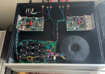
Sound comparison between the “Simple Reflex” for Alpair 10.3/10p and the “Classic Golden Ratio Mar-Ken” for Alpair 10.3/10p

Hallo liebe DIY-Leute,

Wer von euch hat verlässliche, verlässliche Erkenntnisse, wie sich die beiden Reflexgehäuse für den MA 10.3 klanglich unterscheiden? Aber bitte nur gesicherte fundierte Kenntnisse!! Anhand der Zeichnungen lassen sich die baulichen Details einschließlich der Volumina eindeutig ermitteln. Die Ausrichtung von Scotts „Simple Reflex“ für das 10.3 ist Fb = 40 Hz, F3 = 44 Hz mit einem Volumen von rund 17 Litern und Daves „Classic Golden Ratio Mar-Ken“ für das Alpair 10.3 mit einem Volumen von rund 14. 7 Liter. Aber der Klang/Eigenschaften. . . . . . . . ??

Allerdings dürfte in der heutigen teilweise übertechnischen „Audiowelt“ viele „Audio-Jünger“ von der Bezeichnung „Simple Reflex“ abgeschreckt sein, da die Gleichsetzung mit „gut“ oft kompliziert ist – frei nach dem Motto „viel hilft viel“ was dann zu einer Raketentechnik wie Wilson Audio WAMM Master Chronosonic führt, nur weil man meilenweit vom klanglichen Optimum der Punktschallquelle entfernt ist und dann wieder kompensieren muss. Vielen Dank an Scott für diese Einfachheit!

Diese Frage richtet sich natürlich auch an die „üblichen Verdächtigen“!

Vielen Dank für eure Antworten und ein schönes erholsames Wochenende.

Grüße Stefan

Marantz vs Marantz

This is a big forum with lots of members and the chances of someone having an answer that can be useful is therefore high and this one is regarding Marantz PM-11S3 (integrated) vs Marantz SM-11S1 (power amplifier). According to Marantz themselves, these two amps are complimentary to one another and use very similar approaches. Both use the HDAM SA3 as an example, deliver pretty much the same power and so forth.

But I still want to ask if someone has dealt with both and can inform me of if there are any discernible difference in the in the performance arena that I should be aware of ?
  • Like
Reactions: picowallspeaker

Ekta Grande or Ekta 7741

hello all,

i need new speakers, so i want to ask your opinions about this 2 DIY Kits.
The baffle at the ekta grande looks like a promise for a good soundstage.
The 7741 use the newer illuminator chassis.

Ekta Grande

Ekta-7741

i want to go for passive xover this time, even i own a pair of hypex 123 amps which would reduce the cost.
they are a good tool when its comming about making the xover fast and easy and active speakers are always great,but aside of this really big benefits im not so happy.

My room> 5,22m in lengh and 3,85 in width
the speakers are placed left and right of a lowerboard where a 65" TV is. (yes,not perfect, i know it has an impact on the reflections)

on the ceiling i have 18 pcs 50x 100cm Basotec panels which are 5cm thick.
on the opposite site of the speakers is the couch and above that a 240cmx140m acoustic picture which is filled with 5cm basotec panels.
so the treble is well damped, maybe a little to much 😉

Music, well all kind music except jazz.(classic is really rare, maybe one or 2 times in a year.

what i like on speakers, details and more details, a good seperation between instruments.silent things to hear that get lost on cheap shoutboxes.

my past system was a 4 way active seas excel system. with an 35cm baffle.

So, what do you think are the pro and cons of those 2 Kits ?

PP 807 stereo amp with 6F8G or JAN 7193 drivers/preamp

Not used to hifi but designed and built >10 guitar amps.

I’ve got a quad of matched 807’s. Is planning a stereo amp build for my jazz and classical (also some metal) loving son for vinyl playing.
Was initially thinking of a regular pp amp but since I had a quad I was thinking stereo. Been searching the net and found the heathkit series and Stancor.
Do want to take advantage of the coke bottle style so want to skip the 6SN7 and run 6F8G’s (two 6J5’s in one bottle) instead Then I realized that I had 10 pieces of JAN 7193 tubes (one 6J5 but top capped grid and plate). Would look way cooler with eight 7193 up front and the heater current draw is 0.3A (half of a 6F8G).
Regarding the 807’s I was thinking a Vp of 400-450V.

So my questions are:
1) a stupid idea?
2) triode or UL operations? Do not need +70W output
3) have this PT from an old PA amp, will it be sufficient? I can always add an extra filament transformer. Will this PT work?
4) the PT does not have a 5V winding and read that an indirected rectifier tube (like a 5v4 or gz37 if preferred). Any way of getting a 5V output from one of the windings?
5) What are the optimal OPT’s for such a stereo amp. With regards to wattage. Frequency response I was thinking 20Hz-20kHz. Could get a custom made toroidal OPT with or without a UL tap for fairly cheap. I do have one 40W 6.6K:8Ohm as
of now with hifi specs. Is stereo really needed?
6) a choke and what would the “optimal” inductance be? Due to the rectifier choice?
7) any drawbacks with using two 7193’s instead of one 6F8G?

If anyone has a similar schematic for a PP hifi amp it would be very much appreciated.
I’ll attach the schematic from where I could get the PT from.
Centrum pa.JPG

rear radiation of the speaker

Hi everyone .
when you enclose a speaker in an enclosure the rear surface radiates the waves inside the cabinet and after bouncing, a certain part of them come back and hit the speaker membrane.
a fibrous mass or a pyramidal sound-absorbing panel is usually used to solve the problem of standing waves but is it an optimal solution to also solve the problem described above? or are there other methods and tricks? .
bye thank you .

help troubleshooting Parasound A23

Hello,

I have a Parasound A23 amplifier. It has several relays, can be started by audio signal, 12V trigger or manually. I give this precision just in case.

When plugged to the mains you have a P with red light.
When started you have Two blue lights in front.
You also have a Temp light which is always off.

Now the problem.

Amplifier stays online for several seconds or minute then it can :
A switch off the output and the blue lights
B switch off everything including the red light. In that case you have to unplug from the mains and plug again.

I opened the amp. All fuses are intact. nothing looks burnt.

Dont know what could be the problem or what I shall do.

Any thoughts ?

Regards, Greg.

Genelec S30 repair part2

Hi,
Hello,
I trying repair Genelec s30's.
- its a three way active speaker

- bass, mid, treble has it own amp

- changed many parts and got it running.

Problem is treble amp offset reads -32 VOLTS when COLD!!

- treble amps bias is fine

- When amp heats up dc offset drops to +- 50mv, this is withing Genelec specs

- Dc offset bounces a lot when hot, from 50mv to 10mv then to 70mv and back to 50mv

Bias is stable when hot

- Genelec specifies that amp should be measured hot, but this is way too much when cold

- when this amp is working normally, offset is max 200mv when cold. (I have many S30 amp boards that work well)

- offset trimmer pot is tested and ok

- the whole treble amp board was resoldered just in case, looking for bad connection, no changes

- When amp is hot and its turned off for a couple of seconds, DC offset is immediately -5.00 Volts from -50mv. And starts super slowly rising back to 50mv

Where is the fault?

Attachments

  • 20230906_174223.jpg
    20230906_174223.jpg
    152.9 KB · Views: 239
  • 20230906_173934.jpg
    20230906_173934.jpg
    219.3 KB · Views: 216
  • 20230906_153711.jpg
    20230906_153711.jpg
    606.4 KB · Views: 334
  • 20230906_153503.jpg
    20230906_153503.jpg
    180.1 KB · Views: 309

Is This Worth It ... ?

First post... I've gone down the rabbit hole for a couple of weeks and I'm not getting very far (eyroll)

I borrowed a cheap subwoofer from a friend and managed to very quickly kill it dead (the amplifier hum of death)
https://www.hifi-tower.co.uk/Sound-...rs/18-Active-DJ-PA-Subwoofers-2000W-Pair.html

I am wondering if I can de-activate it (scrap the amplifier) and throw a monster cone into it as a consolidatation.
Something like one of these --->

https://www.loudspeakersplus.com/Eminence-Impero-18C-p/eminence-impero-18c.htm
https://www.loudspeakersplus.com/v/vspfiles/templates/driven/pdfs/Impero_18C.pdf
https://www.cedist.com/sites/defaul...mpero-18c-4-cabinet_design_specifications.pdf
"Ideal for two-way top boxes, full-range two-way boxes, bass guitar boxes, and small subwoofers"

I downloaded WinISD Pro (Alpha) but for some reason it won't accept my numbers and throws an error box.
(Screenshot attached)
I am about to download Hornresp now and see if that fares any better.

Internal dimensions of the box are 610 x 520 x 375
This gives a net volume of 118.95 litres.
Minus 6.70 litres for an Impero 18C, .506 litres of brace and two ports (95mm dia. x 110mm deep) .77 litres each,
giving a combined port volume of just over a litre and a half (1.54l)
Approxamite box volume 110.004 litres


Any help appreciated.... Going back down the rabbit hole.


Databass/

Attachments

  • WinISD screenshot.PNG
    WinISD screenshot.PNG
    8.1 KB · Views: 77

Golden Tube SE-40 - Worth screwing around with?

There is a nice example attractively priced near me. Sonic Craft had an upgrade kit for them, and it sounded like a fun soldering project. The reviews I’ve read seem to be “Flawed design, doesn’t meet specs. Sounds fanatic though.” I’ll be ok as long as I can get 20wpc out of it at least

What’s your opinion on the brand/model?

Odd power tube failure, what do we think happened here?

This tube works cold and fails hot. Runs normally for maybe ten minutes and then "just stops passing signal" with no pops or bangs or complaining at all. It just stops. Filament stays lit.

Tube is NOS and failed with a couple hundred hours on it. Perhaps this is a clue? - it operates horizontally and the funny looking getter was near the bottom.

36KD6 Beveridge amp

SPDI/F transport - advice please which at sensible price?

I use CD seldom but have about 1000 classical discs.

My TEAC T1 has started miss-tracking when starting a play sequence. The gears are 100% OK.
As a stop-gap I am using an old PHILIPS 800/II CDP as a SPDI/F (cable) out Transport. It is reliable
and sounds quite good but lacks the information retrieval of the TEAC.

What I require is a used transport at a keen (lowish) price to use with my SUBBU dac.

I am now over 80 years old and due to tremor unable to do any soldering; also I am unaware
of a good repairman anywhere near so whatever is advised as a solution needs to be of proven reliability.

Many thanks​

[Columbus OH] - Speaker garage sale (Morel TiW634Ft, Fostex FF225wk FT48D, Eminence Alpha 15a, Dayton 10" DVC subwoofers)

All prices negotiable + shipping within USA.

Dayton - Condition is good, never used, original purchase ~2010
SD270A-88 - 10" DVC Subwoofer - 4 drivers - $75/pr
DS270-PR 10" Passive Radiator - 1 PR free with driver

Eminence - Condition OK, originally purchased ~2016
Alpha 15a - 15" Paper cone - 2 drivers - $150/pr

Fostex - Condition is acceptable, originally purchased ~2010. These were some of my earliest speakers. Well used and loved, but a little rough.
FT48D - 1.2" soft dome tweeter - 2 tweeters - $50/pr
FF225WK - 8" Paper cone full range - 2 drivers - $150/pr

Morel - Condition is great, purchased early 2022
TiW634Ft - 6" mid woofer - 2 drivers - $225/pr

Attachments

  • Dayton DIYaudio.jpg
    Dayton DIYaudio.jpg
    446.6 KB · Views: 190
  • Emenance DIYaudio.jpg
    Emenance DIYaudio.jpg
    596.1 KB · Views: 143
  • Fostex DIYaudio.jpg
    Fostex DIYaudio.jpg
    547.8 KB · Views: 166
  • Morel DIYaudio.jpg
    Morel DIYaudio.jpg
    407.8 KB · Views: 183

Subwoofer tower help!!

Hey everyone. So I just got done completely rebuilding my Carver Amazing speakers along with a pair of custom made 1k watt mono blocks to power them. They do sound absolutely amazing but do lack a little on the very bottom end. Plus, they are over 30 years old and finding the original 12” drivers in good condition is getting harder and harder.

My crazy idea is to build two towers the same height as my Amazings (66”) using four PE GSR 12SW-4HE in each tower, kinda like the old Infinity ISRs from back in the day. These drivers have a low FS, decent Xmax and are pretty cheap. I’d be powering them with a 2 X 850 watt amp. My goal here is to get as flat of a response as I can down to the lowest frequency possible.

I used WinISD and came up with a 15cft ported enclosure with the port tuned to 20hz. That give a flat response down to 21 hz or so without exceeding Xmax on the power I have. The port would be pretty big (16.75 X 5.5 X 32”) to keep port velocity down but size isn’t really a concern here.

Overall internal space with port, bracing and Wd would be almost 18cft.

So am I missing anything here and how do you think they would sound. These will be strictly two channel music subs. Open to feedback.

Attachments

  • D488E49F-3032-48B5-8757-9AA614908532.jpeg
    D488E49F-3032-48B5-8757-9AA614908532.jpeg
    537.2 KB · Views: 106
  • 52DA1438-2BF2-49DB-82E1-2A31C2DE1BE8.jpeg
    52DA1438-2BF2-49DB-82E1-2A31C2DE1BE8.jpeg
    720.6 KB · Views: 127
  • 65F5C6A9-B0D8-477A-A982-6A91A1ED4E1E.jpeg
    65F5C6A9-B0D8-477A-A982-6A91A1ED4E1E.jpeg
    462.9 KB · Views: 138
  • 5BD966F2-F581-452F-9344-5397E9743D76.jpeg
    5BD966F2-F581-452F-9344-5397E9743D76.jpeg
    783.3 KB · Views: 127
  • 5F3F0A62-833C-4C2E-ADE1-0E9DEC1CC754.jpeg
    5F3F0A62-833C-4C2E-ADE1-0E9DEC1CC754.jpeg
    840.4 KB · Views: 114
  • Like
Reactions: geraldfryjr

Grounding scheme when using rails from different transformer windings

Hello,

I'm building a Tube Guitar Amp vaguely inspired to Mesa Boogie mk IIC+ with some ideas taken from later models and other amps.
I decided to start by fixing a very coarse amp topology and focus on prototyping the power supply first and once tested I will make a PCB.

Before starting to build, I tried to lay down a grounding scheme. Having read the related books by Merlin Blencowe thoroughly, in particular the chapter on grounding, I decided to go for a "local star approach" as strictly as possible, as the amp is high-gain.

However, I think I'm missing some points (I marked in red my doubts on the schematics).
My concerns are mainly related to safety, avoiding damaging the transformers, and avoiding ground loops.

My transformer has the following windings: (345/55/0/345) (3.15/0/0.15) (5v - no center tap) (12V - no center tap)
The primary mains circuit has a double fuse, double switch, a MOV, a NTC, then goes into the primary winding. The safety ground is bolted to chassis close to the IEC inlet. The only other connection to chassis is at the preamp input (see schematics), with eventually a switchable ground lift circuit.

1) On the first winding I'm using two-phase rectifiers since I have center taps. For the other windings I'm using bridge rectifiers. Is it safe for the transformer to connect their ground together (eg. red mark on the top right in the schematics), or would I short a winding/rectifier somehow? Since I plan to always bring wires coupled with their relative ground, my perception is that the connection marked in red only serves as voltage reference and the big flow of current from 12V / 5V rails would flow directly into their capacitor or rectifier, so they shouldn't produce significant hum. Am I correct?

2) One thing that isn't specified in books or posts I've read on ground loops, is what happen if I have to supply a pre-amp section from a different rail.
As you can see in the pre-amp sketch on the bottom, my tube stages in the pre-amp are fed by the same wires (A+ and A-), however I also have a solid state graphic equalizer in the middle of the pre-amp, which needs 24V that are taken by the bias windings. What is the appropriate grounding in this case? I suspect them to be either D- or the preamp ground bus. However, in the latter case, current from D+ would travel a long way down to A-/main reservoir and then... reach the EQ reservoir again? (something doesn't add up to me). In the former case, current from D+ would traverse the EQ and get back to the Eq reservoir in D- a shorter loop, but then I'm not sure what is the signal reference in that case. What is the solution that allows to generate less ground loops?

3) In this case D+ actually comes from the same windings of A+, so they should naturally be referenced to the same center tap, which is connected to the same physical point as A-, so It might be not a big issue. But what if I were to connect the EQ to the 12V rail?

4) As you can notice, there are two separate connections for power amp HT (B) and pre amp HT (A). This is because I plan to design a power scaling circuit from Merlin's book, which allows to drop the voltage of power amp B+, screens and bias voltage, leaving the rest unaffected. It will stay on a separate board, since I want to try the "stock version" of the amp first to measure actual voltages and actual maximum power. Again, I have to provide two different voltages to two components in the signal chain, and I'm not sure how to think. I maked it as a possible ground loop, but I don't really think it is the case.


I apologize for the wall of text, but I couln't make up my mind. Feel free to point out any other silly mistake you spot on the schematics 🙂.

Thanks!

1696026948293.png

Attachments

Jamo R909 open baffle, Accuton Cell speakers, Plitron & Tribute Audio output transformers

I have the following for sale. Local pickup only. Augusta, GA 30809

$7,000 - Jamo R909 black gloss - Revelator 9700, Seas Hexadym, 2x 15" woofers (21" surface area) per speaker
$2,000 - Clearwave Symphonia speakers in cherry - Accuton Cell c25-6-158 tweeter & C90-6-724 midrange, Scanspeak Illuminator 7" woofer


Measurements:
Jamo R909 (now owned by Klipsch)
Revelator 9700 - Hificompass - https://hificompass.com/en/speakers/measurements/scan-speak/scanspeak-d2905970000
Seas hexadym midrange - VoiceCoil Review - https://audioxpress.com/article/test-bench-seas-w15ch001-5-25-excel-hexadym-motor-midwoofer
Brochure: https://assets.jamo.com/files/r-909-whitepaper.pdf

Clearwave Symphonia
Accuton Cell c25-6-158 - Hificompass - https://hificompass.com/en/speakers/measurements/accuton/accuton-c25-6-158-cell
Accuton Cell C90-6-724 - Hificompass - https://hificompass.com/en/speakers/measurements/accuton/accuton-c90-6-724
Scan-speak Illuminator 18wu-4747T00 VoiceCoil Review - https://www.scan-speak.dk/datasheet/reviews/18WU-4747T00-VoiceCoil_2010-4.pdf

The Scanspeak 9700 is one of the lowest THD tweeters there is. Hexadym midrange is excellent for open baffle due to magnet design and measures well.
Accuton Cell midrange is HiFicompass's favorite Accuton midrange, costs $742 each; the cell tweeters $542 each. The underhung illuminator aluminum woofer is tested in VoiceCoil to have 10mm xmax, 4mm beyond spec. The paper version has been reviewed by Erinsaudiocorner and is similar with less xmax.

Attachments

  • IMG_20221204_132207966.jpg
    IMG_20221204_132207966.jpg
    337.3 KB · Views: 414
  • IMG_20221009_150636026_HDR.jpg
    IMG_20221009_150636026_HDR.jpg
    234.5 KB · Views: 254
  • IMG_20220909_140518360_HDR.jpg
    IMG_20220909_140518360_HDR.jpg
    329 KB · Views: 267
  • IMG_20220909_140436285_HDR.jpg
    IMG_20220909_140436285_HDR.jpg
    361.2 KB · Views: 205
  • IMG_20220622_064944182.jpg
    IMG_20220622_064944182.jpg
    367.6 KB · Views: 179
  • IMG_20220622_065715769.jpg
    IMG_20220622_065715769.jpg
    386.2 KB · Views: 203
  • IMG_20201212_183037391_HDR.jpg
    IMG_20201212_183037391_HDR.jpg
    291.6 KB · Views: 204
  • clearwave speakers brochure.jpg
    clearwave speakers brochure.jpg
    370.9 KB · Views: 197
  • IMG_20221204_132118210.jpg
    IMG_20221204_132118210.jpg
    346.5 KB · Views: 188
  • IMG_20220622_065601446.jpg
    IMG_20220622_065601446.jpg
    373.4 KB · Views: 187
  • IMG_20201212_183327422.jpg
    IMG_20201212_183327422.jpg
    210.1 KB · Views: 180
  • IMG_20201212_184626906.jpg
    IMG_20201212_184626906.jpg
    207.4 KB · Views: 249

Valve PA amp - what to do with it?

IMG_20230928_184428895_HDR.jpg


IMG_20230928_184443145_HDR.jpg


IMG_20230928_184912373_MFNR.jpg


IMG_20230928_184922688_MFNR.jpg


IMG_20230928_184929713_MFNR.jpg


IMG_20230928_184934525_MFNR.jpg


IMG_20230928_184941117_MFNR.jpg


IMG_20230928_184906615_MFNR.jpg


*This has already been posted in another section, I've copied it here as well on the advice of a fellow member. Mods, please delete if you feel the other section is more appropriate

I have a valve PA amplifier which has been my possession for many years. It was my late grandfathers. I've never seen it working. It's complete but would obviously need a fairly comprehensive overhaul before it could be used. The valve line up is EL34, EL34, ECC81, 6BR7, 6BR7, ECC82. There are 2 EZ81 rectifiers also.
It's an strange old thing which has the option of running from a 12v battery. It has a wierd mains/battery socket on the front. I think it looks pretty cool and would love to use it as a guitar amp and build a little cab for it to sit on top of, finishing both the amp and speaker cab in a matching quilted leatherette similar to the beaten up stuff that's already on the amp casing.
Whatever happens, it stays as it looks now. It won't be cannibalised for parts!

The issue is that I can't find a schematic for it. I've looked many times over the years and come up with nothing.
Searching on Google just brings up old posts on vintage-radio, (one of which was made by myself), another gives some interesting background info on the company who made it. However there's no schematics posted anywhere.
If I had a diagram to follow I'd be able to make better sense of the circuit but as a relative beginner, it's beyond my capabilities to trace out the entire circuit.

So, I'm thinking of just starting from scratch and finding a suitable guitar amp schematic which uses the EL34's and rewire it that way.
I've no use for the 12v circuitry etc...

I'm thinking a good starting point would be to make sure the transformers work, these being the most expensive things to replace.

If anyone can suggest a guitar amp that could be make use of as many of the existing components as possible, let me know.

Any ideas on how to precede will also be welcomed!

Bass response in room, box simulation compared to measured response

Hi,

here some data to show magnitude of effects room has on bass response, and how much bass box alignment matters in comparison.

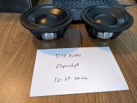
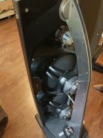
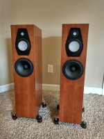
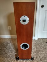
Short story: I've had some 15" woofers for many years and have been prototyping a speaker system with three way mains speaker equal amount of time. Currently on third bass box version for the mains, and I've been downsizing every time as I've always had to EQ the lows lows down to match up sensitivity of rest of the system. Also, I've felt there is coloration of sound from the bass box, which ought to reduce by better construct, smaller panels, modes inside higher up in frequency, minding about the port and so on. In general, as box gets smaller any issues get higher up in frequency, hopefully beyond pass band and out of harms way and should reduce any "box sound".

But that would compromise the bass, right, making box smaller than a simulator suggests? True if only looking anechoic response on the screen and forgetting the box will be in a room along with rest of the stereo playback system. And in this case, a 15" bass provides plenty enough for my home use, so there is extra SPL potential that can be sacrificed. Your system and context might differ, so please post if you have an example, perhaps even a counter example.

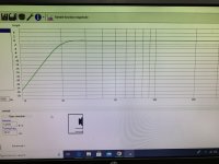
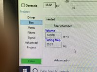
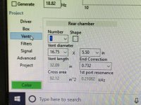
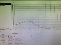
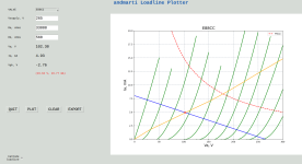
Anyway, my first box is already scrapped so approximating a bit. I remembered it was 150l but it was likely smaller as simulator suggests 113l for the driver automatically. Lets assume it was 113litre and try to remember the tuning. Second box was and still exists about 80l. Third box is sealed and only about 50l. Here are box simulator responses for the three, all using the same woofer:
113litre-reflex-box.png80litre-reflex-box.png50litre-sealed.png

Dramatic difference, right, the 50litre box response drops much higher than the other two and should have underwhelming bass. Also the 80litre box should shame on the 113litre, which should have much "better" bass, right, that's what the simulator automatically suggests at least.

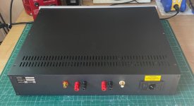
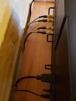
Let's find out, here is measurement of one of the boxes. This is box that does sub woofer duty right now, and one of the three above. Mic was at listening spot, ungated sine sweep. Can you guess which one of the three is it? You can guess it reasoning with the text above, but the important bit is can you read the box alignment from this graph? The reflex boxes are tuned around 40Hz but here is crazy dip around 40Hz.
measurement-at-listening-spot.png

No, I cannot read the aligment. It's the 80l reflex box.
Here is the box simulator SPL graphs from all three above overlaid on the actual measurement, see correlation now? I cannot still 😀
measurement-at-listening-spot-with-sims-overlaid.png

The green line is the corresponding simulation. Huge 14db peak above simulated SPL at 33Hz and 11db dip at 39Hz with the room and positioning I happened to have this time. I'd say the response would be pretty much the same regardless which one of the tree enclosures it was, a 113litre reflex box or 50litre closed box. They would have some differences, but none would measure like the simulation.

ps. the measurement voltage was not calibrated so the amplitudes are matched roughly by eye.

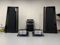
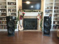
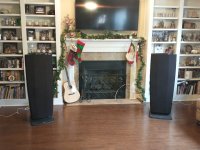
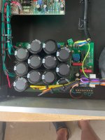
Alright, here is the 50l closed boxes, main speakers Left and Right and both overlaid. The boxes are at different location in room being Left and Right main speakers, while the mic stays put.
mains-left.pngmains-right.pngmains-both.png

On these graphs the measured responses show trend of the simulated response quite nicely, varying roughly +/-10db due to influence of the room. I have to use EQ to make sound better like with all of the boxes. These small boxes sound lean without EQ and the bigger reflex boxes sound boomy without EQ, and with all of them it's very hard to get system bass nice sounding, which I attribute to peaks and dips in the response but of course could be anything as I'm a hobbyist.

Anyway, to get some feel on magnitude of things: If the room influence was translated into amplifier power it would mean that if I fed 10W to the speaker, the dips would be equivalent of feeding 1W power (10db less) and peaks 100W (10db more), total effect of room is 100x amplifier power! Looking at the combined graph, around 47Hz the left channel has 16db more output than the right, that is 40x difference in amplifier power between Left and Right channels, due to room.

So, manipulating positioning of things is very important, while box alignment is less important, almost meaningless in comparison at least in this particular example.

Lesson in my particular case presented here: as the room already ruins the bass response and manipulating it to liking would require separate bass system and EQ, or at least EQ, I could further ruin the bass without any extra harm by sacrificing some of the extra bass output that box simulators originally suggested, just tweak the EQ. This allowed to make smaller box that's both easier and cheaper to build, easier to accommodate and position in room, has less audible issues on midrange and bass performance is pretty much still the same as before, dominated by the room! I had to use EQ on all of the boxes to make system response balanced.

Based on this experience I don't mind main speaker bass alignment too much currently, other than better make it so that midrange works as well as possible, basically to optimize everything else than the bass. I feel main speaker bass box alignment has very little to do with perceived bass quality, instead one should consider utilizing separate bass system that is specifically adjusted with the room to get the response you want with SPL capability you want, by what ever means suit you like using some gradient bass system, positioning, EQ, multisub, tearing down the room, what ever.

Many of you already know all this, but many of you don't, like I didn't when starting off spending hours in front of WinISD looking at wrong things. It was interesting to see the graphs today, so though to share. Have fun!🙂

External amp to power a broken sub?

Hi.

I have a KRK 10S 150w Sub speaker. When I power it the main fuse blows, I've gone through a few fuses fault finding but with no joy in finding a fault, Therese nothing obvious when I look inside the unit, blown caps etc. New whole parts (ie pwr supp) are thin on the ground as its pretty old, to replace the whole thing would be about £400 2nd hand.

In short I want to get a stand alone amp (150w), drill a whole in the sub cab and connect directly to the speaker from the amp bypassing all the electronics of the unit and just utilising the cab and speaker, feeding the amp from the SUB op of my DtoA converter which in turn is fed from the Dolby Atmos software (sub op).


Can anyone recommend a "cost effective" preferably class D, balanced input amp that could do this. The speaker is 8ohm, 10 inch. Or tell me why this is a bad idea!?

Thanks!

s-l1600.pngUnknown.jpeg

Hum

Hi,

About 3 years ago I built an amp based on a Champ using parts from an old unidentified amp. It has recently developed a constant hum, regardless of the volume position. Its not really loud, but since it used to be really quiet, I want to figure out the reason. When building it, I used new good quality capacitors, but some resistors I did recycle, as well as the tubes that came with the amp. Before I open it up, I'd like to ask if there are points I should check with a volt meter to help find the reason for the noise. I've attached the schematic. Some resistor values have changed, and noted, but the updated schematics are inside the amp.

Thanks

Attachments

Hello from San Leandro, California

Hi all!
I stumbled on to this board looking for speaker specs (salvaged speakers from TVs, cheaper speaker cabs, computer speakers, etc) AND I am going to recreate one of my favorite sets ever.
At some point in the early 80's I made the double chamber reflex speakers from Weem's book "Building Speaker Enclosures" and yes, I was at R/S at least once a week going back to the early 70's!

Right now I have a pair of JBL 166's that I re-foamed years ago and a pair of Infinity 120's (also re-foamed). And I'm looking at a pair of Mitsubishi SS 152's for $200 ea in fairly good shape.

I want to be able to get accurate numbers so I can make better/funky, weird enclosures for some of these "no-name" drivers (because, why not?) and so far it looks like the the Dayton Audio DATS (thoughts, suggestions?)

Ciao!

Hello from Sheffield UK...

Hi - thanks for having me here. I'm Tim from Sheffield, UK. I'm a sound engineer (Studio and TV outside broadcast) by trade but compose semi pro in my spare time. I've just put together my Dolby Atmos 7.1.4 room at home, mostly for experimentation rather than as a commercial venture. I'm looking for advice with simple electronics problem solving in the studio environment, not building. And I will now reading some of the very interesting posts on here!!

Thanks!!
  • Like
Reactions: Captain B

vituixCAD crossover from library block

hello,
a newbie here, first time XO planning. i used the 3 way crossover from the library and tweaked it. i have a few questions hope i can understand the answers 🙂

drivers
T - Dayton Audio AMT Mini-8 Air Motion Transformer Tweeter 8 Ohm
M- Dayton Audio PS95-8 3-12 Point Source Full Range Driver 8 Ohm
S- Dayton Audio LW150-4 6 Low Profile Woofer 4 Ohms

1, can thes XO can be simpler to build? less parts or smaller parts
2. what do you think about the values of the components and the overall graph?
3, can you guess the cost of the parts? rufly

1695146007998.png

For Sale Avondale Audio SE200 power amplifier

For disposal: I have an Avondale Audio SE200 power amplifier which is surplus two requirement as I have now upgraded to the SE400's.

The transformer is an Audio Grade 540va from Tiger Toriods
The SE200 amp boards have been populated with exotic component variants (audiophile types) in appropriate locations.
The power supply is the latest offering from Avondale the NCM3 with 60,000uF capacitance per rail totaling 120,000uF in total for the amp, and incorporating Schottky rectification (MBR10200)
The power supply also has its own soft start onboard!!
The case is from Modushop 2U 400mm deep, the facial is unmarked new.

Audition welcome by arrangement (Hampshire UK)

£1500

Free hipping to UK only
.

IMG_2032.jpg

Attachments

  • IMG_2034.jpg
    IMG_2034.jpg
    235.4 KB · Views: 178
  • IMG_2025.JPG
    IMG_2025.JPG
    480.7 KB · Views: 217
  • IMG_2030.JPG
    IMG_2030.JPG
    551.2 KB · Views: 249
  • IMG_2036.jpg
    IMG_2036.jpg
    440.5 KB · Views: 245

For Sale Fostex FE208e∑ Drivers

Hello. I have some Fostex FE208EZ drivers for sale

https://www.madisoundspeakerstore.com/approx-8-fullrange/fostex-fe208ez-8-full-range-sigma-series/

The total usage between them is less than 2 hours

I have 3

2 for $350 plus shipping. Make an offer on the third/a single

Attachments

  • 20230927_181127.jpg
    20230927_181127.jpg
    574.8 KB · Views: 87
  • 20230927_175916.jpg
    20230927_175916.jpg
    326.1 KB · Views: 89
  • 20230927_180022.jpg
    20230927_180022.jpg
    394.2 KB · Views: 90

Stupid question: Where do amps come from?

Let's say I've built a power supply with a transformer that converts 120v to 25v, and then a bridge rectifier, and some filter capacitors. Now I've got 25VDC to connect to my equipment. What determines the number of amps my equipment can draw? Is it the total capacitance of the filter caps? Then I guess there's the transformer, and then the wall.

To put it another way: If I double the capacitance of my power supply, did I just double it's maximum amperage?

DAC as an USB to SPDiF converter

I have decent studio DAC from Antelope Audio model Zodiac Gold. I use it mainly to play files from HD since I have a decent library of redbook , High rez and DCD files .For a change of presentation I took it's SPDiF output to feed an older dac which has no USB input effectively using Zodiac as a USB SPDiF. I have problem with noise between tracks . Any idea how to fix it ?
These are specs on Zodiac digital outputs
1x AES/EBU De-Jittered, re-clocked Digital Output. 110 Ω. 2x S/PDIF De-Jittered, re-clocked Digital Outputs. 75 Ω.
I will add that input of an older Dac either re-clocks the signal or uses custom jitter reduction process (those are the options to chose)

EL34 UL PP Transformer

I plan to build a classic EL34 UL PP amp. One of the big questions is which output transformer to use. I know this has been asked before but the most recent thread I can find is 4 years old and a lot can happen in the world of transformers in that time. I am in the UK so European suppliers would be preference but not essential. I am aware of the Sowter offering but that is a little expensive for my tastes. I am looking for something of reasonable quality that is not too expensive, i.e. good value for money.

Recommendatiion?


Cheers

Ian

Push-pull load lines for GU-50-Triode - did I do this right?

After a recent thread about load lines for push-pull tube amps, I decided to try matching triode-wired GU-50s to a couple of OPTs I have lying around. One has 8k ohm (plate-to-plate) primary, the other about 5k ohms. Check my work? Did I do this right?

GU-50_Triode PP 8k and 5k OPTs compared.jpg


I chose Vp-k of 380V and Ip of about 80mA (Vg1 of -60V) because that's a reachable set of operating points with power transformers I have available.

What would be the disadvantages to using an OPT with 5k pri? Are there significant advantages to using an OPT with 8k pri?

SSE - Choke and Supp Cap Position

I'm working on the layout/parts ordering for my build which is slowly coming together. So far, I had planned on positioning the Power Trans and OPTs conventionally at the top/back of the chassis - i.e. Power trans in one corner, rotated 90 degrees to the OPTs. positioned side by side at the other side. My question concerns positioning the choke and supp cap.

To save size and space on the main chassis, I could build a small frame inside the enclosure, using V slot 2020 aluminum (grounded of course) and mount the choke on it below the Power trans and the supp cap laying horizontally on the frame under the OPTs.

Does anyone foresee a problem with that approach?

FS: Black Gate NX Hi-Q capacitors

These were kept in stock by me only to be used in excellent equipment. I decided to sell them as the DIY frequency is not high enough to justify keeping stock. These were all bought from an official distributor. I never noticed deterioration but of course they need the hours for "breaking in". These were bought when the announcement came that production would stop.

These values are in stock, I checked prices but they vary a lot. I don't recall what I paid for them except that is was a very expensive affair. I do recall thinking that I bought caps with a combined value of a nice second hand car 🙂

BG NX Hi-Q 47 µF/6.3V 25 Euro/piece
BG NX Hi-Q 22 µF/6.3V 17.50 Euro/piece
BG NX Hi-Q 0.47 µF/50V 12 Euro/piece
BG NX Hi-Q 0.1 µF/50V 10 Euro/piece

I have many other values and series and will post these later on.

Attachments

  • iu.jpeg
    iu.jpeg
    89.1 KB · Views: 1,145

JL 1000/1 PWM comparator

I have a 1000/1 on the bench which shorted a pair of output FETs, but replacing them didn’t solve the problem. When it turns on, it makes a shrieking sound...

After some poking around with the scope I realized that all the output gates have drive, but the on time isn’t balanced between the high and low side like I would expect. The PWM is unbalanced all the way back to the comparator. Probing pin 5 of U511 shows the normal sawtooth coming from the 555 timer as expected, and pin 4 is 1.7v. Sure seems like pin 4 should be higher, like maybe around 2.5v?

Can anyone verify what pin 4 should be, and if that’s what’s wrong, what sets the DC on that pin? Offset pot had no effect.

Adding Bass to monitor speakers (not a subbass)

I'm getting deaf with age and work related issues. Worse it becomes more I like mainstream electronics and speakers most of you guys love so much but can't afford 🙂
I found on the curb a pair of MBL 311E piano finish speakers which I quite like even though they sport 17cm Davis kevlar midwoofer , material I used to hate. They do well in the "mimicking bigger speakers " department mainly thanks to severe shelving the efficiency to mere 84db/4 Ohm . Manufacturer quotes 44Hz . I do not want to touch the crossover in the speakers I just may introduce 6db high pass filter . I would like to add some true bass , mid bass from at least 10" woofer . Separate enclosure bi amped . I'd either replace stands with the box or build two tower boxes standing next to the speakers in unfortunately narrow but long space (10 ft wide). Is it something worth pursuing or I'd be wasting my time? I dismiss subwoofers. I have those in the corners of the room. Sealed , tight but it's not gelling with mains in the proper way. I need a driver in direct line with kevlar midbass.
https://stereonomono.blogspot.com/2018/12/mbl-311e-speakers.html

Attachments

  • blog-MBL311E.png
    blog-MBL311E.png
    140.3 KB · Views: 190

New forum: Electronic design

We have a new forum category to discuss electronic design.

This allows for a logical space where concepts that are unrelated to a specific piece of hardware can be discussed, such as the pros or cons of wide of narrow bandwidth in electronics or the intracies of feedback.

https://www.diyaudio.com/community/forums/electronic-design.200/

I think Jan will get the ball rolling shortly... 🙂

Convert DSP input from analog to S/PDIF

Hello! I have an older DSP that doesn't have a digital input.

I have the schematic for it. The A/D converter is a PCM1802. Fairly certain I've seen digital input boards for a reasonable price. Would it be as simple as disabling/removing the current A/D and connecting power to the converter and connecting the data/LRCK/BCK/MCK and selecting the interface mode?

Why are people still touting the Mullard 5-20 circuit?

If we believe Morgan Jones when he writes in "Valve Amplifiers" of the 5-20:

"The input stage is an EF86 pentode, which is responsible for the high gain but poor noise performance...."

"The cathode coupled phase splitter is combined with the driver with the driver circuit using an ECC83...... The output stage has an input capacitance of ~30pF, and combined with the 53k ohm output resistance of the driver stage, this gives a cut-off at ~100kHz, which is quite poor."

"....the driver stage has only 10dB of overload capacity. When the output stage gain begins to fall, for whatever reason - cathode feedback, input capacitance loading the driver, or primary inductance in the output transformer - the global feedback loop will try to correct this by suppling greater drive to the output stage, and the 10dB margin will be quickly eroded, raising distortion."

Jones goes on to discuss the output tube's individual biasing resistors and their bypass capacitors, "The capacitor is a short circuit to AC, and so prevents feedback, but its reactance rises at very low frequencies, so it is no longer a a short circuit, and allows feedback. Because the output stage is load matched, this feedback causes an immediate rise in distortion and reduction of power output due to the mismatch."

There are other points as well, I've just chosen a few.

Isn't it time we moved on from the Mullard 5-20?


Cheers, Steve
  • Like
Reactions: stenak and peteki

2 way 12 inch horn?

Hey guys I got an idea instead of buying and selling commercial speakers, thinking about building or buy a kit or a project with a 2 way horn speaker, with a 12 inch and a compression driver,my goal is clean and low distortion,and a good directivity horn with a proper horizontal distortion,(wider is my preference as I think they sound the best in a home environment, here in Italy we have faital drivers , and I think they could be good candidates, and I already have 2 18n862 BMS subwoofer that could be crossed at like 100hz Soo the 2 way speaker could be crossed little higher, do you have any opinion about this project? Thanks!

Lucky me, I have a pair of original Z565 OPTs -- But I have 4 ohm speakers...?

I was going through the closet, looking at what's sitting there on the shelf. It seems I squirreled away the iron from an old Dyna ST35 amplifier. (Its PCBs burned up back in the days before JLPCB made it so cheap 'n easy to have your own made.) I was recently given a nice aluminum chassis that's pre-drilled for a quartet of 9-pin output tubes and a couple of 9-pin driver tubes, with room for transformers, etc. Obviously, this has to be a project.

The speakers I want to use are all 4 ohms. I have a pair of Snell E/III that I like, and are supposed to have 91dB sensitivity (but at 1W? 2.83V? I don't know).

The Z565 OPTs have 8 and 16 ohm secondary taps. I think their primary impedance is 8k plate-plate.

What would happen if I used 6P43P (EL86) tubes instead of the EL84 (6P14P) tubes the OPT was designed for?
  • Running the 8k:8 rated OPT into a 4 ohm load on secondary would make it 4k:4, would it not?
  • 6P43P has half the rp of EL84, so should be happy into a 4k p-p primary load.
  • Z565 is supposed to present 100H primary inductance. Does that change if the OPT secondary is underloaded? Or is the primary L relatively constant?

Thanks for any help with this.

Lost in EU Kits - Needing some direction

Hi all, I just joined and I'm building my first "real" hifi/ht system but feeling a bit lost (lots of variety!).

For the past months I ended up spending probably too much time researching, reading and watching YouTube videos about various speakers. I also went to a couple hardware stores to figure out what I value in a speaker the most.

Anyways, since I'm doing a HT and wanted to have the same speaker all around, I thought of going DIY, but since it's my first DIY build I wanted to go the kit route. The problem is, all the time I spent researching was mostly about kits and speakers based in the US. And when it comes to EU, the websites are all barebones (as in a nightmare to navigate and find straightforward info) and even here it's a bit hard to find information or similar posts to what I wanted. I decided to just write this and see if some of you could help or give me a general direction to follow.

The room I'm putting these in is quite small 5x5 meters. It's a living room/home theater hybrid so that's both music and home theater, they are going to do double duty, I already did some room treatment for the projector, so I can do the same for the acoustics, that's not an issue. That being said there's a couple shelves on the sides. We will probably move in the next couple of years for a bigger space tho, so I really wanted something that I wouldn't have to ditch in a slightly bigger room.

After spending hours with multiple speakers in store, I tried most of the recommended brands. There was a single speaker I fell in love with, and that was the q acoustics concept 50. Which I was going to purchase but then I started making the math and with concept 30 surrounds it would add up. Plus since my center will stay behind the screen I would really prefer to have the LCR to be all the same and that would mean I'd have to buy an extra pair since they aren't selling singles. If I had to describe what I liked, it was the detail and soundstage compared to the others, so I guess I fall more on the analytical side of things. I also tried some Arendals, and I loved those.

Worth noting, these will be connected to probably a Marantz Cinema 50 for starters. I will add some dedicated amps as I go.
I also don't care much about the deep low end, as I'd prefer to have a dedicated sub or two for that job.

So I guess my question is, is there a DIY speaker or parts that would give me a similar sound signature? I apologize for not being more throughout as I'm a bit of a newbie when it comes to speakers. I spent my entire life just using headphones (Audeze LCDS).

Thank you in advance!
EDIT: Can't believe I forgot, besides movie duty. The music we most listen to is Indie, some Metal, a bit of Pop with a high emphasis on vocals and the occasional EDM.

Loadline plotter

Hello. Having done some utility apps for using my Keithley 2015 to measure my amps (https://github.com/andmarti1424/free_keithley), I just started this python project yesterday:


e88cc.png


Its hosted on github as well: https://github.com/andmarti1424/loadline_plotter and its GPLv3.

I really like other similar loadline plotter like Merlin's Excel o VTADIY one.

But the problem with the later is that is not free and the loadlines data is not downloadable.
I really like to have hover over the plot to see the Va and Ia values.
And in VTADIY you cannot change maxY value so graphs sometimes shown too narrow.

The app current status is basic funcionality. It lacks validations, more useful data to show.
Remember its just a few hours of work.
Hope someone find it useful and if so, can help with PR...
Thanks.

Attachments

  • e88cc.png
    e88cc.png
    65.9 KB · Views: 111

QA401 Audio Analyzer up for Sale (+QA350 DC-meter)

I have a pristine QA401 Audio Analyzer available for sale.

I purchased it in a moment of despair when I thought I had broken my RTX6001, but fortunately, that was not the case in the end. I have only briefly tested the QA401 and never used it for anything serious, so it's as good as new. I bought it directly from QA in May 2020.

Please send me a private message with reasonable offers. We all know the value of this analyzer, so I will ignore offers below a certain threshold.

Additionally, I have a QA350 24-bit µV DC meter that I can bundle with the QA401. It's in an equally mint condition, as I never really understood what I needed it for 🙂

Cheers, Nic

The QA401 is sold

Formula request - Power required for driver at xmax by frequency

I'm trying to model maximum excursion for several drivers in a spreadsheet.

I have Max SPL per frequency as a function of Sd and Xmax. Max SPL obviously increases as frequency increases, leading to power / thermal handling limits - credit to a Jeff Bagby post:

SPL= 20 * log(10) (1.18 / 0.00002 * Sd * Xmax / SQRT(2) * 2 * PI * F^2)

Where Sd is in Meters^2
Xmax is in Meters one-way linear travel
And F is the frequency you want to solve for.

What I now want is the power limited formula equivalent (such that I can "cap" driver output above the point where Xmax would demand more power than the voice coil can handle in heat).

I have a power formula that uses driver Sd, Mms, BL and Re, but it seems to be about ~6dB out when calculating max SPL given max continuous driver power.

Can someone please post a formula or links to good references?

I tried to reverse engineer Linkwitz' closed box spreadsheet, but failed (maybe too tired). Linkwitz' model is better in the sense it caters for per frequency variable impedance, but I'm more concerned at the top end, not necessarily driver Fs or cabinet loading impedance changes.

Thanks!

For Sale 12” Denon DA-302 tonearm and direct drive motor dual EDS-1000-2

A very nice broadcast tonearm by Denon specifically made to match the 103, clearly can be used with other cartridges as well.

Tonearm is in great conditions, rewired with silver cables, original head shell included but it needs one wire to be soldered (I preferred a modern head shell) and its original tonearm rest. Bearings are perfect, the tonearm was restored a few years ago.

And a direct drive motor with platter and rotary switches. It is a truly excellent motor. I just dismantled my proto turntable as I did not use it any more for years now

Tonearm 500€ or best offer
Motor and platter 100€ or best offer

Plus shipping costs from Italy

Attachments

  • IMG_2926.jpeg
    IMG_2926.jpeg
    383.6 KB · Views: 170
  • IMG_2925.jpeg
    IMG_2925.jpeg
    293.7 KB · Views: 150
  • IMG_2924.jpeg
    IMG_2924.jpeg
    340.6 KB · Views: 168
  • IMG_2923.jpeg
    IMG_2923.jpeg
    334.1 KB · Views: 167
  • IMG_2922.jpeg
    IMG_2922.jpeg
    433.8 KB · Views: 173

Tubelab SEII Chassis

So I was planning on posting a whole set of - how I built my SE II and got all lazy but thought folks might find this useful.

I had trouble with Hammond 276 and 376X power transformers running REALLY hot so ended up going to a B373EX which is HUGE, but runs really cool. Used Edcors for outputs and mil-spec Vishay-Dale resistors (Mouser) or matched ones from Sonicraft.

All of the resistors are mounted on the top and caps on bottom. Board is mounted with 1/2" long standoffs to give clearance for the resistors and put the tube sockets about flush. All the board mount and transformer mount screws are 10-32 button head screws.

Super oversized heat sinks on the mosfets and power IC which resulted in this chassis arrangement with digital current meters for bias monitoring.

So what you get are some pictures but also PDF's that if you print full size will give you the hole layouts for everything. I tried to make notes on the PDF's but if you have questions, post them.

The transformer covers are from Ebay and work great. The small handles over the switch and front and back are there to protect connectors and frankly, aesthetics.

I used Greenlee chassis punches for the tube and switch holes as well as a bunch of vent holes in bottom cover.

The front RCA inputs are probably not ideal visually but keeps cable runs to absolute minimum.

I have large motor run cap set in the underside of chassis in a 3D printed clamp.

There are four extra holes in the top to expose the four adjustable pots and I cover them with little plastic plugs.

The whole thing is not small but its been running fantastic for well over a year now. AND SOUNDS AMAZING! Just wanted to get this out there for folks that might be interested. I will post a more comprehensive build over time. Biggest thing is I could not have built this without George and this community so just trying to give back!

Attachments

QuantAsylum QA400 and QA401

The QA401 is now available and it has differential inputs and complete isolation from the host PC. Starting around here http://www.diyaudio.com/forums/equipment-tools/231401-quantasylum-qa400-186.html#post4657822 is discussion of the QA401 and some measurements. With the new version my efforts on a balanced out and differential in become less important but they still may help someone.

Several of us have been playing with these for a few months now. They are an inexpensive "sound card" USB capture device that has been optimized for audio measurement. More here: QA400 Audio Analyzer

The performance is quite good. More than adequate for any normal audio measurement need and the software works well, avoiding the usual problems with the Windows sound engines. It provides many good measurements as is and hopefully will get extended by others for specific tasks.

The one problem is that the I/O is single ended and limited to around 1V. This is fine for mobile audio stuff like iPods but not enough to work well with more conventional audio with 2V+ levels and amps good for much more.

In my prodigious free time (as in none) I worked out a design for an interface card to match the QA400 to real world audio devices. Its similar to Pete Millet's interface Soundcard Interface but not as refined or pretty. It also is two channel and doesn't have the metering, since the QA400 is quite accurate.

For the I/O I realized that making interface cables with appropriate connectors would resolve several issues. I have something like 5 pounds of adapters to go from anything to anything, however most end up as part of a link from one connection type to another. Usually for me its a dual BNC to Banana adapters to single BNC to dual banana to clip leads. Pretty dumb. My idea (borrowed from the Praxis interface PRAXIS INFORMATION ) is to make cables that have the appropriate adapter as part of the cable. The I/O is 3.5MM stereo connectors. This would be a stereo 3.5mm connector used as a differential interface terminated into an RCA for line level or two bananas for spoealer level, or XLR for balanced interfaces. Then the cable can have attenuators built into it eliminating the need for overload protection required for a dual banana type input.

I decided to steal power from the USB interface and make it a pass through. I'm using a DC-DC converter to get enough voltage to get 10V RMS out. I won't know until its built if this worked so easily.

The IC's will all be socketed on mine so they are easy to replace when they get fried.

I got my assistant Tim to do most of the heavy lifting on the layout. We have checked it and have sent it out for fab. We should have PCB's and parts in a week to build and test the design.

I am attaching the schematic and layout, all in Expresspcb ExpressPCB - Free PCB layout software - Low cost circuit boards - Top quality PCB manufacturing since I feel its very appropriate to this project. Please feel free to point out the dumb mistakes I made and improve it. The software is free from them.

PLEASE DON'T ORDER ANYTHING UNTIL I KNOW IT WORKS! I will post a revised version after I have made the first ones work.

Attachments

  • Poll Poll
65Hz or 170Hz for stereo subwoofers

Please provide reasons in comment.

  • 65 Hz + mono operation

    Votes: 7 50.0%
  • 170 Hz + stereo operation

    Votes: 7 50.0%

I have two subwoofers for stereo subwoofers setup. Each subwoofer is placed next to each left and right main speaker. Since the electronic crossover, a/d/s/ 642ix, has fixed frequency module. It requires to change the module to alter crossover frequency. The currently available modules are 65Hz @ 24dB/octave and 170Hz @ 24dB/octave. And the electronic crossover allows to select either mono or stereo subwoofer operation. The manual suggests to set the operation to stereo mode only when the crossover is set above 100Hz. I need advice which setting I should use. Note that this is two subwoofers system, not usual single subwoofer setup. Please vote the poll and reply the opinion on comments.

Help finding DIY community approved quality stereo amp

Hi, I'm in a hunt for a decent stereo amp available to buy as a device or a DIY kit with a budget around 150EUR.
I've spent last 2 days reading the forum and watching reviews. I didn't found a particular highly rated model, thus decided to ask. The usual suspects are the TPA3255 (Aiyima, BRZ) or MA12070 (Topping PA3S) packages but I can't pick a winner. Also "some say" they can't come close to something like Cambridge Audio AXA25.

My needs are very simple - low noise amp, stereo input from a PC and 2x30W output for a 8ohm Mark Audio Alpair 10p drivers.

I have access to soldering stations at my work so I will consider a model which can benefit from better capacitors or some other easy upgrade.
One thing I will greatly appreciate would be a USB audio interface so I could eliminate the need for a quality sound card.

Any recommendations?

XT25 3d printed WG adapter question and ID

I printed a set of adapters to fit my Visaton WG148 waveguides thinking I had the correct STL file, but it looks like its for another WG.

Its been a while since I downloaded the file and I dont remember.

Dimensions are 4.5" OD and the opening tapers to 50mm. I'm not sure if its intended for the Monacor WG300?

Can someone tell me which file is the correct one for adapting the Peerless XT25 to the Visaton WG148 and possibly ID the adapters i printed?

Attachments

  • 20230927_074933.jpg
    20230927_074933.jpg
    347 KB · Views: 95
  • 20230927_074905.jpg
    20230927_074905.jpg
    317.2 KB · Views: 103
  • Like
Reactions: Bryguy

Discussion: Unwanted clipping in solid-state e-guitar preamps

For years, I've heard a sort of low-level gritty harshness from solid-state electric guitar amplifiers, when set for clean tone.

I'm talking specifically about solid-state, all-analogue guitar amps that follow the typical recipe: op-amps in the preamplifier, and an IC power amp (or a rarer discrete power amp stage).

For a long time (decades!), the cause of this phenomenon eluded me. I didn't know what caused it, I didn't have the test equipment to capture it, and not every musician even heard it at all.

So it was basically a case of "He said, she said", and that is a very unsatisfactory situation for what is fundamentally an engineering problem.

I think I now finally understand the cause of the harshness I've heard so many times, and I'd like to talk about that in this thread. Hopefully this is of interest to other people who want to build solid-state DIY guitar amplifiers, or simply want to understand them better.

The starting point for all of this is the actual electrical signal from an electric guitar. Exactly what does it look like?

Fortunately for me, Rod Elliott, a name familiar to most DIY electronics enthusiasts, had made a number of measurements of e-guitar signals, with the intention of finding out the amount of voltage that could be expected from a typical e-guitar.

While Elliott's goal was to calculate peak and RMS voltage from a guitar, he also posted screen captures from his oscilloscope on his website: https://www.sound-au.com/articles/guitar-voltage.htm

There are a lot of interesting things to be seen in those guitar signal captures.

More in the next post.

-Gnobuddy

RIP- Rick Craig of Selah Audio...

He died of a heart attack this weekend.

This is sad. Rick was one of the 3-4 people that were present at my first experience in hifi, about year 2000. I've told the story before a few times, but;
We met in Ft Wayne down on HWY 24, IIRC. Rick was in town from NC visiting his folks in FW, who still resided here at that time. JeffB, Rick, myself and another fellow I don't remember met at Applebee's. 4th guy left after lunch. Rick's folks eventually moved to Indy where we also met once more about 2005.
After lunch we went further into town to a HiFi shop which is now closed. I heard Jennifer Warnes played on B&W Nautilus 801, via a massive McIntosh tube amp. I was the inexperienced one here, and Jeff/Rick agreed that the treble was sssibilant, and that the bass was okay but didn't extend all that deeply for a 15" woofer. We all thought the mid was spectacular.

He was what I consider one of my mentors, and will be missed. He has touched many a soul through his speaker-designing business, and I've not heard of a disappointment with any of his products.

He really knew his stuff.

Wolf

Noisy kids

Hi my neighbours kids are driving me crazy, tried asking parents to intervene with no joy
Bearing in mind I know nothing about audio et cetera, I'm aware that there is certain sound which only children can hear and which may deter them from the area around my fence
Is there an app, combined with a high volume Bluetooth speaker, or something anyone can recommend that will put an end to my misery 😟
PS I'm in the UK

Marantz CD75ii laser not moving and CD just spins

Hi guys, got this as faulty from online. Buyer stated disk just spins and does not read CDs I was hoping its just the blue cap under the laser but no joy!

When I put a cd in it just spins and laser does not go up or down and I cannot see a bean either.

I've checked most of the rails and on the chips and they all seem ok as far as I can see.

Any experts on these old players? Its 100% not the cd mechanish as I tried that in a working unit and it was fine.

Ive been using CD65DX service manual but the device is CD75 II

Any help appreciated.

Attachments

PSU for tube mic - A good 47uf / 250v?

I have a late 1950's Neuman U47 mic that has gotten noisy. Obviously, this mic deserves the best components available.

I don't have a scope, so can't test most thing, but I figure it might be a good idea to change the 64 year old electrolytics in the power supply.
Sure, they might still be fine, and they don't meke 'em like they used to, etc, but it seems logical to do it now.

There are two 1000uf / 50v, and those are no problem. I can easily fit Nichicon LKG's there.
However, there are also four 47uf / 250v axials, and I'm having a very hard time finding a suitable replacement even in a radial cap, hence this post.
The original caps are FRAKO GPF series, (polarized electrolytics) and are no longer made. I saw some vintage nos ones for sale, but what sense does it make to buy really old electrolytics?

I would love to pop some polystyrene's in there, but space is a real problem.
(I'm also not clear on whether I can use non-polarized caps there.)
Even a really good electrolytic, like maybe a Mundorf MLytic, is too big. The max diameter I can easily fit is about 20mm.

One alternative would be to use decent electros (or smaller film caps and glue them to a different area in the enclosure. However, that would require pretty long leads, maybe 4-6". Would that be a problem?

Or maybe use a bit less capacity? I assume these are bypass caps, yes?
Still Neuman surely knew what they were doing, so....

------------------

I may just change the big caps first, and see how it sounds, but even if that cleaned things up, should I consider changing the others as well?

-----------------

Anyway, does anyone know of a really good, but fairly compact, cap I can use? (axial or radial, I don't care.)

- thx
Projects by fanatics, for fanatics
Get answers and advice for everyone wanting to learn the art of audio.
Join the Community
507,774
Members
7,888,127
Messages

Filter

Forum Statistics

Threads
406,221
Messages
7,888,127
Members
507,774
Latest member
pete2000