When winding output transformers I've come across the term "spiral winding" of the secondary windings.
The idea is that sometimes the secondary windings won't fill the whole width of the bobbin.
This will cause increased stray inductance, and the remedy is spiral winding on parts of the bobbin.
So, my question is;-is this what it would look like?

The idea is that sometimes the secondary windings won't fill the whole width of the bobbin.
This will cause increased stray inductance, and the remedy is spiral winding on parts of the bobbin.
So, my question is;-is this what it would look like?
I can't help with your question, but if allowed add the next one. I always liked the OPTs with 4 equal secondary windings, much like the standard outputs from Sowter https://www.sowter.co.uk/push-pull-output-transformers.php
Besides offering flexibility at the output, wouldn't the 4 equal windings imply that the problem of not filling the whole winding is eliminated?
Besides offering flexibility at the output, wouldn't the 4 equal windings imply that the problem of not filling the whole winding is eliminated?
To fill a full layer, I'm usually going multifiliar with a fine wire. I've reached deca filiar layers on some projects. That allows for maximum efficiency of fitted copper on a layer.
I think it depends on the transformer.
Winding output transformers seems like a puzzle full of compromises.
It looks easy in theory and on paper, but there are many factors involved often working against each other.
Wire gauge, number of turns, impedance ratio, interleaving pattern, isolation between layers, bobbin width and height, fill factor, lamination size etc.
If stray inductance is not an issue it becomes simpler, but if it is an issue it gets more complicated.
50AE --->Sounds like a much better solution than spiral winding.
-I never thought of that possibility.
-I never thought of that possibility.
I fully agree about the puzzle full of compromises. Furthermore, doing it well for OPTs requires some serious equipment (to lay the layers nicely, not some scramble winding...) for which one needs space. And all the rolls of different wires, the cores...
I am very happy that there are still people doing this as it is so important for this hobby, chapeau for them!
I am very happy that there are still people doing this as it is so important for this hobby, chapeau for them!
Simply said, you change one small criteria on your OPT requirements and chances are you'll have to redesign it all over again. After building some, say, 300 different types of audio transformers, you kind of memorize so much interleaving patterns and variations, that it begins feeling like building Lego.
I have re-wound simple transformers by hand. Quite possible, but it takes a long time and it's very boring.I fully agree about the puzzle full of compromises. Furthermore, doing it well for OPTs requires some serious equipment (to lay the layers nicely, not some scramble winding...) for which one needs space. And all the rolls of different wires, the cores...
I am very happy that there are still people doing this as it is so important for this hobby, chapeau for them!
Transformer winding seems very tricky, and experience is probably most important.Simply said, you change one small criteria on your OPT requirements and chances are you'll have to redesign it all over again. After building some, say, 300 different types of audio transformers, you kind of memorize so much interleaving patterns and variations, that it begins feeling like building Lego.
For a newbie like me it would be tempting to rush along with a huge amount of primary inductance to ensure good low frequency response only to get to a point where stray capacitance starts to eat away at the high end of the frequency spectrum.
You add at one end only to have it taken away at the other end if not careful.
It seems like a balancing act which is only mastered by experience.
What I remember from the time I was winding stepup transformers for ESLs, is that it's always better to completely fill the space with copper if low leakage inductance is your goal. So either use thicker wire, or use multiple parallel wires. Leaving space in between the windings will result in significant higher leakage.
On the other hand, more copper area increases capacitance. You can use thicker interwinding isolation to reduce that effect, the price being increased leakage again. So pick your compromises...
On the other hand, more copper area increases capacitance. You can use thicker interwinding isolation to reduce that effect, the price being increased leakage again. So pick your compromises...
Another reason for filling the layer with wire by spiral winding is that it gives a more even foundation or bed for the next winding.
Very much doubt that is a real problem.This will cause increased stray inductance, and the remedy is spiral winding on parts of the bobbin.
Stinks of overthinking and "non solutions for non problems"
And in any case, will apply to one layer only, the last one, since all others have been filled end to end by definition.
IF there is any influence, it will be microscopic.
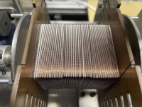
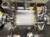
If winding won't fill the whole width of the bobbin there are several solution:
1) Even distribution (on photo 1).
2) Thin film-insulated (e.g. Nomex) flat (ribbon) litz wire (photo 2).
3) Multifilar winding as explained 50AE (he is one of the best transformer experts on this forum).
4) "Spiral" winding pattern with uneven distribution (mentioned by Emtor) have higher leakage inductance compared to the first 3.
Attachments
I would suggest you to take well designed receipts from Patrick Turner, copy if his defunct we site available here:For a newbie like me it would be tempting to rush along with a huge amount of primary inductance to ensure good low frequency response only to get to a point where stray capacitance starts to eat away at the high end of the frequency spectrum.
https://www.vacuum-tube.eu/www.turneraudio.com.au/index.html
LinuksGuru---> Yes, I've downloaded all relevant pages from turneraudio.com.
Thanks BTW for the two other methods I was not aware of.
Thanks BTW for the two other methods I was not aware of.
A completely random thought that just struck me - since the design of an O.T. covering 20Hz to 20kHz in one unit involves a bunch of compromizes due to the importance of stray capacitance at high frequencies and the need for lots of inductance at low frequencies, could you not use two transformers to cover the audio band, secondaries in series to combine and perhaps an elementary passive cross-over on the primaries?
This idea is done with speaker drivers for basically the same reason...
This idea is done with speaker drivers for basically the same reason...
Not in this way like you describe, 2 separate amps for each channel with 2 speakers, e.g. 20-200Hz and 200 - 20,000Hz.could you not use two transformers to cover the audio band, secondaries in series to combine and perhaps an elementary passive cross-over on the primaries?
I (and many others apparently) had the same idea:A completely random thought that just struck me - since the design of an O.T. covering 20Hz to 20kHz in one unit involves a bunch of compromizes due to the importance of stray capacitance at high frequencies and the need for lots of inductance at low frequencies, could you not use two transformers to cover the audio band, secondaries in series to combine and perhaps an elementary passive cross-over on the primaries?
This idea is done with speaker drivers for basically the same reason...
https://www.diyaudio.com/community/...and-into-two-transformers.286621/post-4611092
Z winding isn't worth it for most OPTs, where primary to secondary capacitance usually dominates. Z winding only reduces primary to primary capacitance from a factor of 1.33 to a factor of 1. Primary to primary capacitance is very small in most OPTs, usually ranging from 100 to 300pF. This is because.
-OPTs have a high number of primary layers, so voltage gradient between them is quite small. Capacitance decreases exponentially with voltage gradient difference.
-OPTs are usually interleaved, and splitting primary layers reduces further the capacitance, as they get connected in series, hence imagine capacitance packages in series.
I'd say it is worth in other applications, such as little count transformer layers like for SMPS or chokes.
- Home
- Amplifiers
- Tubes / Valves
- Transformer spiral winding

