UN-Thermal Tracking an ARC SD135 amplifier
- By Zero Cool
- Solid State
- 29 Replies
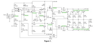
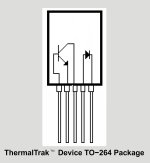
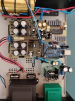
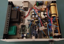
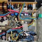
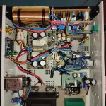
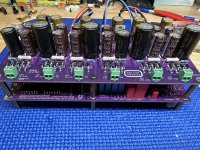
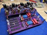
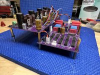
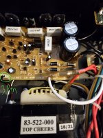
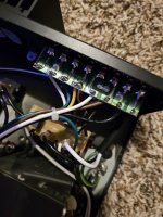
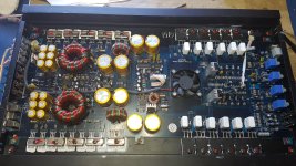
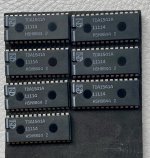
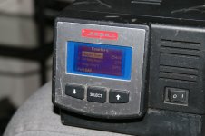
I have an ARC Sd135 amplifier that uses the now defunkt Thermal track output transistors. these are failure prone devices and despite the MFG's attempts to fix the issues with them, the product failed. The Thermal track NJL3281 is just a standard MJL3281 with an added internal diode. what fails in these is the thing that is supposed to make them better, the added Internal Thermal Tracking diodes! and that is exactly what has failed in the amp I am working on. thankfully it failed without doing any damage. often times that is not the case. Often times the output devices overheat and short. In my amp the output devices are still intact, but the diodes inside have gone wonky as that is the best way to describe what happens. leaky is maybe a better term. In this amp the bias is WAY out of range and jumps around all over the place. Looking to save this amp, I need to come up with a solution.
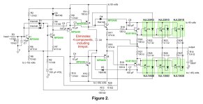
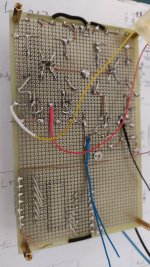
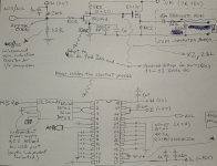
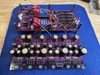
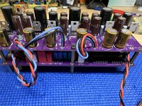
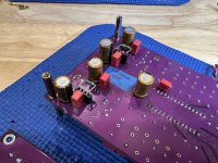
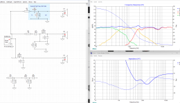
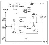
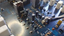
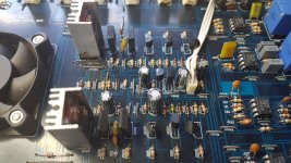
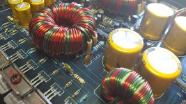
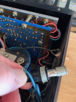
I disconnected the string of internal diodes and I experimented with an external string of 1n4148 diodes. 5 diodes gets the bias close to being in range but I would need a way to mount 5 diodes in contact with the output devices or the heatsink. Looking at the Thermal Track whitepaper they show an example with a standard VBE Multiplier. I like that approach better as it is adjustable and I did some experimenting by breadboarding up the VBE circuit and attaching the A06 transistor between 2 of the output devices on the massive heatsink they are mounted on. and with some tweaking I was able to get the amp to idle pretty close to factory spec. which is about 100ma per output device averaged across all the devices. 20mv on the .2ohm emitter resistors. I was able to get the amp to idle for 1 hour at about 18.6mv per device. BUT, I ran the amp at 1/3 power for 5 minutes and then back to idle and i observed that the bias was quite high. about 30mv per device. I may need to move the bias transistor to the middle of the heatsink and maybe come up with a better clamp for it.
*
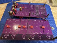
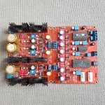
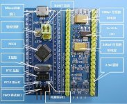
But before I start too far down that rabbit hole. I thought to throw it to you guys for some (TV show House ) diagnostic style input! I don't want to redesign the whole amp. But I can make a small daughter board with the VBE Multiplier on it that could be adapted to the amp.
Thoughts, feedback, Input?
I disconnected the string of internal diodes and I experimented with an external string of 1n4148 diodes. 5 diodes gets the bias close to being in range but I would need a way to mount 5 diodes in contact with the output devices or the heatsink. Looking at the Thermal Track whitepaper they show an example with a standard VBE Multiplier. I like that approach better as it is adjustable and I did some experimenting by breadboarding up the VBE circuit and attaching the A06 transistor between 2 of the output devices on the massive heatsink they are mounted on. and with some tweaking I was able to get the amp to idle pretty close to factory spec. which is about 100ma per output device averaged across all the devices. 20mv on the .2ohm emitter resistors. I was able to get the amp to idle for 1 hour at about 18.6mv per device. BUT, I ran the amp at 1/3 power for 5 minutes and then back to idle and i observed that the bias was quite high. about 30mv per device. I may need to move the bias transistor to the middle of the heatsink and maybe come up with a better clamp for it.
*
But before I start too far down that rabbit hole. I thought to throw it to you guys for some (TV show House ) diagnostic style input! I don't want to redesign the whole amp. But I can make a small daughter board with the VBE Multiplier on it that could be adapted to the amp.
Thoughts, feedback, Input?


