Best 7k output transformers for 46 triode SE amp

Looking for opinion on the best 7k primary output transformers for a 46 strapped-in-triode for use in a Single Ended amplifier. I know that Hashimoto, Tamura, and Tango make or made 7k primary transformers but their low-end bass performance is curtailed to 30 to 45 Hz. Are there any 7K OPT that go down 20Hz or less? Did MagneQuest ever produce a 7K transformer? I know that they did a 6K FS-007.

Tribute Audio use to produce excellent 7K transformers. Are there any other high quality 7K OPT available today that deliver great bass from a 46 strapped for triode operation?

What is the best 7K OPT for this application in your opinion? Whether still produced or not, which OPT’s stand out with 7K primaries?

Thanks in advance. Your opinions and guidance is appreciated.

F6 Illustrated Build Guide

Mosfet F6 Illustrated Build Guide

The Firstwatt F6 is a power amplifier from the brilliant mind of our technical, spiritual, and menu advisor, Nelson Pass.

The F6 is unique in that it uses a transformer for phase inversion, and both phases (The ‘push’ and the ‘pull’) of the amplifier are powered by an N-channel device.

This guide uses this PCB set — F-6 clone boards (2 PCBs, makes 2 channels; Rev 2.0) - Circuit Boards
Or here, the PCB with transformer bundled - F-6 Board + Transformer Kit – diyAudio Store
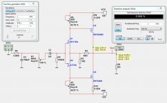
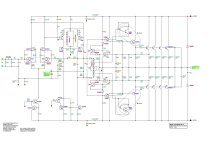
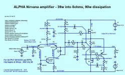
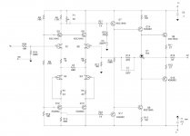
F6PCB.jpg


SCHEMATIC

The Schematic can be found here -

F6_DIY_SCH.gif


CHANGES TO THE SCHEMATIC - Change Z1, Z2 to a value higher than 5.1V if you need more bias. Increase in ~.5v steps until you can bias properly. The 1N4xxx series diodes are used here, 1N4733 is 5.1v, 1N4734 is 5.6v, 1N4735 is 6.3V, etc...

Suggested change, make R11, R12 110ohm. More information can be found in the BOM.

And an example PSU is here -

F5PSUschematic.jpg


diyAudio PSU v3 build guide — diyAudio Power Supply Circuit Board v3 illustrated build guide


CHASSIS

The example amp is build into a diyAudio Deluxe 4U chassis — Deluxe 4U "Jack of all Chassis" (All Aluminum) V2 - Full width with 40mm Heatsinks - Chassis

Also utilized was the diyAudio Premium back panel parts kit — Error 404 - Page Missing

ASSEMBLY


Here are the PCB. The production boards are blue, and have some very slight changes to the silkscreen, but are otherwise identical.

Note that the PCB are a matched pair, not 2 of the same PCB. This is to facilitate keeping the input transformer as close to the back wall (and away from the power transformer) as possible.


Stuff resistors first.


After the resistors, stuff the larger components. Jfets, pots, capacitors, etc…


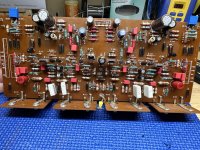
A stuffed PCB, sans transformer and LEDs (Didn’t have any blue ones on hand. 🙂 )

4080013.jpg

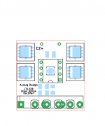
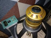
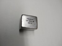
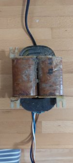
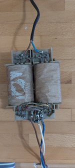
Input transformer. Note that on pair of pins is slightly narrower than the others. There are corresponding pads on the PCB for the narrow pins.


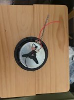
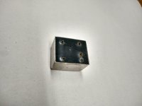
Transformer mounts here.

4080014.jpg

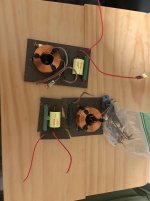
Both transformer mounted.

4080017.jpg

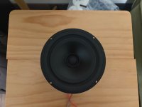
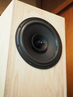
Remember, for best heatsink efficency, the mosfet should mount towards the bottom. This heatsink will make the left wall of the case.

4080018.jpg


4080019.jpg


IMG_3384.jpg

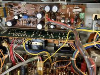
You can see all the wiring of the PCB in this photo. (Red Black Green) is from the PSU, (Black White) is to the speaker posts, and the thin coax connects RCA to input.

IMG_0661.jpg


Black is PSU GND and Speaker negative
White is Speaker positive
Red is V+
Green is V-


IMG_3386.jpg

Input wiring from RCA


IMG_0664.jpg

Completed, working amp. Need only to finish assembling the chassis around it.
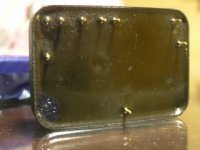
(The black box on the transformer lead is a clamp-on ferrite clamp. Necessary? No. Might it help? Yes.)


IMG_0666.jpg


IMG_0665.jpg


POWER SUPPLY

IMG_3374.jpg

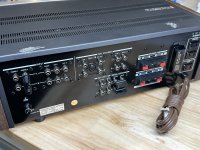
IEC socket. You must wire the fuse holder to the switch as shown.

IMG_3377.jpg

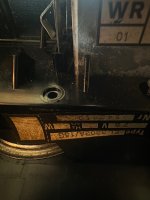
The long wires go to the terminal block with CL-60s, line cap and then the transformer primaries. I needed a bit huskier wire for the safety earth, and added the yellow for clarity.

IMG_0657.jpg

PLEASE NOTE - this shows 120VAC wiring. Please consult your transformer for proper wiring for other voltages.
Into the block you can see the thermistors and cap, the AC mains from the IEC switch (Red Black) and the transformer primaries (Black Brown White Orange)

IMG_0656.jpg

Safety earth and the CL-60 used to elevate PSU ground.

IMG_3173.jpg

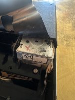
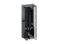
Two things to note - 1) I didn’t know if the power transformer was going to magnetically couple with the input transformers, so I wanted it as far away as possible. This will be almost touching the front plate. The L bracket was something I had from a salvage broken amp, so I can’t suggest a part number. Sorry. 2) Although I didn’t use the current PSU PCB, you can see that there is sufficient room (barely) for the board you can buy from the store.

IMG_3177.jpg

I used an older diyAudio PCB that I had on hand, mainly because I really wanted to use it up.
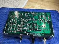
IMG_3176.jpg

Bridges mounted.

IMG_3193.jpg

Wiring up the PCB.

IMG_3194.jpg

More wiring.

For those of you wondering why I choose to have 2 big caps on one side and 4 on the other, it’s simply because I had those caps in my box. There’s no gain nor detriment to doing it in this manner.

IMG_3195.jpg


IMG_3381.jpg

The secret to clean wiring? Simple - start with your leads overly long and trim as you need to, and use lots of zipties. 😀

IMG_0662.jpg

You can see the connections from transformer secondary to bridges and from bridges to PSU board.

IMG_0655.jpg

PSU lit up.


TESTING AND POWERUP

Test PSU first for proper voltages BEFORE connecting amplifier circuit boards.

Then, connect only one amp PCB at a time.

Power Up

I suggest starting with a meter across the 0.47ohm source resistor, and watching it as it turns on, you want to have less than .5V across it to begin, turn it down with P2. If you start with the pot in it’s default position, it will most likely have too much bias initially. Turn off the power, turn down P2, and try again.


BIAS


P2 is marked BIAS on both PCB. Adjust this pot as necessary to set bias. Please note that as the pots and source resistors have the 1000uF capacitor in-between, the adjustments will happen in slow-motion and take a while to stabilize. Make small adjustments and wait as necessary. Patience is a virtue.


With DC voltmeter across the 0.47 source resistor, start by setting a bias reading of .5V (500mV) This will give a current of 1.05A, (.5V / 0.47ohm = 1.05A) which with a 24V rail gives about 25W of heat. Then zero your DC offset. Once you are satisfied that everything is stable and happy, you may increase the bias if you choose.

Remember the 3 rules of maximum bias… stop when you reach any of these -

Heatsink of 55C and/or Transistor pin 2 65C
Total bias , both channels, (in watts) of no more than 1/2 the power transformer’s VA
1/2 the maximum dissipation (in watts) of the output device. In the case of the IRFP240, it’s a 150W device, so no more than 75W. (Which is really, really hot…)

Generally, you will reach the 65C limit of the transistor before anything else.


OFFSET

P1is marked OFFSET on both PCB. Adjust as necessary to set 0V DC across the speaker terminals. Again, because the capacitor needs to charge and discharge as you make changes to the pot, any input to the pot will take some time to display on the meter, and it will seem as if it’s reacting in slow motion. This is normal.

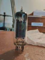
Lightbulb Mains lead notes -

bulbtester1.jpg


Please note that it must be an incandescent light bulb, not an LED or Florescent.
If the bulb ever turns on and stays bright, you probably have a short.

Normal operation when turning on a cold amp will have the bulb glow bright for a second or two, then dim, perhaps off. (this is the capacitors charging, then full)

As you increase the bias of the amp the bulb will glow brighter, and this is linear with the bias amount. A fully biased amp can get the bulb to glow very bright.

You cannot set full bias with the bulb in place - as it increases the bulb will glow more, limiting the voltage to the amp and all the readings will be wrong compared to when the bulb lead is out.

You can, however, set the initial bias with the bulb in place. Start the procedure, turn the pots until something happens, and set, at maximum, 0.1V across the source resistors and zero offset. Getting the pots started this way is a good idea. Remember, this is with a reduced voltage, and the pots will make the circuit draw MUCH more bias when the normal mains lead in used. Expect to measure 0.2V or more with a normal cord.

Class-D: Galvanically isolate the output stage?

Today many run their DACs directly connected to their class-d amps. I do. Amps with several 100 watts output and over 10A amps out.

I would guess that the signal ground in these amps are not the cleanest one could see. And here comes my culprit... the delicate ground in DACs where both clock ground and Vref grounds are tied up to the dirty class-d ground. Probably not ideal.

Pwm_amp.jpg


Why not make the PWM signal interface (red marking) after the "C" optical and let the input part float compared to the output stage. The only harmful part left sharing ground would be the triangle generator.

I bet such a combo of DAC and amp would be quite better sounding... what do You think?

//

PCM58- and Alternatives

This is a thread with everything discussing PCM58, and excellent chip which deserves it's own forum.

I want to resume some of my findings right now after months of juggling with many iterations of this chip in single ended dacs from China.

I will post some %%% in front of information which I could verify almost 100% by trial and error, oscilloscope and signal analysis.

%%% the signal must be 44, 48, 88 khz 16 or preferably 24 bits to the AK4118 receiver or it generates digital noise in the audio band. I don't believe any degradation from using higher resolution recording to downsample as the jitter/noise is the major quality factor here.

%%% the dac can be adjusted with trimpots, MSB, to 4th bit. It is a cumbersome process which doesn't necessarily translate to better audio quality, it is IMO necessary for the MSB and second bit. But further is no need, as the music is so complex it drowns any improvements and other factors are more important.

%%% Like the TDA1541, I find that 4X OS is the best by far, and 18bits only no less no more.

%%% In such a DAC the fidelity of the rendering is very subjective and imo not the reason why one would use such a DAC. I found futile to compare recordings/source (in DeltaWave) to assess the quality of the rendition. I did some visual checks of the waveforms screenshots vs originals and there is no visual differences. Mostly, one should focus on what details can be heard, and how much secondary voices (and complexity) are standing on their own or drowned, and how well the audible speech is rendered (are 'Rrrrs' realistic, Fss), and finally how deep and accurate is the soundstage.

more to come. And possible comparisons with PCM1701.
  • Like
Reactions: percival007

PSB Image tweeter repair

I just finished doing a writeup of how to repair PSB Image tweeters. I haven't found any information on the internet on this topic, but there is floating around many recommendations for a third party tweeter which I do not think is a great match. In the hope that this information is useful to someone I'll leave a link to my blog/whatever:
PSB Image tweeter repair guide
  • Like
Reactions: wyup

For Sale SEAS MR18REX/XF (H1699) Coaxial Units with crossovers, Offers only please

(Updated due to miss information on drivers). Good Evening. I have up for sale a Nice pair of Seas Coaxial Units from the 1990’s I think model T17-(H823) with crossovers for sale. They both work and preform as they should. Pulled them from a pair of speaker Cabinets. The drivers have no damage or issues or does the tweeters. The frames have some of the black finish chipped off because I had a hard time getting them out of the routed hole they were in. They are shielded and are not new but, Lightly used. I have no idea the price they costed brand new? Here are some pictures of them and the crossovers. Am just throwing in the crossovers and not asking for them in the price. 1 crossover is broken in half but, you can make a new board and solder them point to point like the intact one. Am asking for decent offers and not low end offers. Buyer will have to pay shipping to the 48 United States only. You can P.M. Me or E mail me. Thanks Jeff

Attachments

  • IMG_6607.jpeg
    IMG_6607.jpeg
    407.8 KB · Views: 90
  • IMG_6605.jpeg
    IMG_6605.jpeg
    511.7 KB · Views: 91
  • IMG_6608.jpeg
    IMG_6608.jpeg
    421 KB · Views: 90
  • IMG_6664.png
    IMG_6664.png
    431.3 KB · Views: 37

MarkBass Little Mark 250 Bass Combo Amplifier - Need Help With Repair

Hello!

I got a faulty bass combo amplifier MarkBass Little Mark 250. But it appears to be a little more complicated than those I worked with before.
In general, I'm at a dead end, hoping for help from experienced forum members.

Symptoms:
The midpoint between the output darlingtons floats at idle relative to the ground (in the negative direction), when the difference reaches about 1V, the DC protection circuit is triggered and turns off the speaker.

While the amplifier is cold, it floats a lot. As it heats up, it stabilizes (it heats up decently, up to 60-70C degrees at idle) and works normally for a long time. Only sometimes the relay clicks for a second.

All supply voltages are normal, I unsoldered all the electrolytics, ESR is normal, does not show leaks...

Where to dig next?

How is this middle point adjusted there?

The purpose of some parts is a complete mystery to me, such as T3, T4, T6 for example...

I've drawn the schematic of the amplifier part of the combo:

MarkBass Little Mark 250 Schematic.png

Rate my filtering

Thought I'd see what people think about a little two way I've made before spending money on crossover components. Nothing too special, a Dayton DSA 135 woofer and SB26 STCN tweeter. I assumed there would be a dispersion mismatch and there is. There is also a notch in the DI at 350hz that I'm unsure of it's cause. Speaker was measured outdoors on a 10ft ladder. I have plenty of experience with active filtering but wanted to try passive for various reasons, one being to verify my measurement process.


two way test filters.png


Reverse null

dsa135 sb25 two way SPL reverse null.png

LT4320 based active rectifier

hello folks,
here is something i have been working on for some time.
I am willing to offer the pcbs as a group guy.
let me know if there is interest.
I will share a bom to GB subscribers, all mouser based, if GB goes ahead.
regards
Prasi

Edit 1: Group buy closed for THT PCBs, but still open for SMD PCBs. More info in the below link.
Group Buy List
group list qty_new - Google Sheets
Schematic SMD LT4320 rectifier LT4320 based active rectifier
Schematic THT LT4320 rectifier LT4320 based active rectifier
Schematic LT4320 CRC PSU PCB: LT4320 based active rectifier

Edit 2: Revision in prices. (price drop!)
LT4320 based active rectifier

Edit 3: GB closed for SMD PCBs. Only last 10 pairs of THT pcbs remain.

THT BOM BY MERLIN EL MAGOO LT4320 based active rectifier

EDIT 4: New GB for LT4320 based CRC PSU PCB Started..PCB's Produced and being shipped..-Completed and closed...
1. The Design: LT4320 based active rectifier
2. The PCB design: LT4320 based active rectifier
3. Physical PCB's: LT4320 based active rectifier
4. The BoM : LT4320 based active rectifier

EDIT 5: Group buy sign up has begun for modified SMD and THT rectifier boards with ENIG finish and earlier LT4320+CRC PSU PCBs.
Please sign up at the below google sheet with your DIYA username and qty required against each pcb type.
LT4320 based active rectifier
Some 3D views of how the actual PCB assembly looks like
SMD: LT4320 based active rectifier
THT: LT4320 based active rectifier
CRC PSU PCB : LT4320 based active rectifier

EDIT 5: HAVE ALOOK AT PAGE 78 AND 79 FOR ALL PCB DESIGN IMAGES, SCHEMATICS AND 3-D MODELS AT ONE PLACE.

Attachments

  • LT4320-NEW.png
    LT4320-NEW.png
    6.4 KB · Views: 7,507

For Sale Binding post terminal cups - 60 available - great deal

New/unused - High quality compact terminal cups with gold-plated binding posts, 8awg bare wire/spade/banana/dual banana

$3 each - 60 available
$80 for all 60 pcs.

same as: https://www.parts-express.com/Round-Speaker-Terminal-2-15-16-Gold-Binding-Post-260-283

Please see photos below. Shipping from PA 18951 - not incl. /$TBD, either USPS or Fedex. PayPal only.

IMG_5458.jpgIMG_5431.jpgIMG_5432.jpgIMG_5433.jpg

For Sale CAPS! Film, F&F - Duelund, Mundorf, ClarityCap - priced to move

Please see photos below. Shipping from PA 18951 - not incl. /$TBD, either USPS or Fedex. PayPal only.

(Qty)
(2) Mundorf Supreme Silver/Oil 0.82uF 800VAC 1200VDC - $15 each (used, short leads)

(2) Duelund VSF stacked Cu foil 2.2uF no voltage rating - $25 each (used, full length leads) SOLD

(2) Russian Teflon FT-3 0.22uF 600V - $12 each SOLD

(2) ClarityCap MR 3.3uF 630V - $18 each (NOS/new) SOLD

(4) ClarityCap ESA 4.7uF 630V - $6 each, $20 for all 4 (NOS/new) SOLD

(3) ClarityCap ESA 1uF 630V - $5 each, $12 for all 3 (NOS/new)

(2) ClarityCap ESA 0.1uF/100nF 630V - $4 each (NOS/new)

(4 left) ClarityCap SA 3.9uF 630V - $4 each, $12 for all 4 (NOS/new)

(2/2/2/2/2) ClarityCap DTAC 630V M8 screw mount 2uF/2.7uF/3.3uF/4uF/4.7uF - $10 each or $60 for all 10 (used)

Thanks for looking! Make an offer for all if you like...


IMG_5440.jpgIMG_5441.jpgIMG_5442.jpgIMG_5443.jpgIMG_5446.jpgIMG_5448.jpg

Attachments

  • IMG_5447.jpg
    IMG_5447.jpg
    70.5 KB · Views: 119

Is there an Italian member that could help me?

Hi,
I'm interested in purchasing some audio item in Italy but i would like some help from some fellow italian member:
Item is on 'Subito' and being outside the country i can't register ( afaik), so i'm unable to contact seller to know more about the deal ( not even talking how good i'm in talking Italian...).

Please contact by pm if willing to help me to get in touch with seller.
Thanks in advance
  • Like
Reactions: geoturbo

Phillips Cassette Player

Hi there,

I have a Phillips Cassette Player with a broken motor. I am looking for somewhere in the United States or Europe to get this fixed.

Type: EL 3302A/15G
Voltage: 7.5V
Frequency: 50/60 Hz
Manufacturer: Philips
Motor markings: WR 01 941


I believe that the motor I am looking for is a small DC motor, likely a 7.5V brushed type used to drive the capstan and reels.

Does anyone have any advice to where I can find one of these and/or get this fixed? I am located in California, but again, can send it anywhere.

Thank you.

Attachments

  • IMG_5680.JPG
    IMG_5680.JPG
    728.5 KB · Views: 121
  • IMG_5681%202.JPG
    IMG_5681%202.JPG
    458.1 KB · Views: 123

Board 3 Way DSP Amp

I will post the availability and price of the 3 Way DSP Amp boards here.

TOP Plastina+ESP32.jpg


Read more about the boards here.
https://www.diyaudio.com/community/threads/3-way-dsp-amp.415065/#post-7734899


The price of one 3 Way DSP Amp board is $95.

The price of one I/O board is $15.

Delivery to Europe and America is at my expense. Delivery to islands or other distant places is negotiated separately.

Order more than one 3 Way DSP Amp board and get $5 off.

Payment via Payoneer.


We currently have four 3 Way DSP Amp boards and four I/O boards with ESP32 available.

What's up with Lii Audio/ Lii Song?

In my search for a monster open baffle woofer I stumbled the W21 21" open baffle woofer. It looks interesting but the more I research Lii Audio the more something seems off. I cannot find much objective information on them. Most of the people talking about them seem to have conflicts of interest. Then I found there are more than one version of this driver....some may even be copies or made by another company?

The driver on Alliexpress looks very different from the one for sale on lii-audio.com website.

The first one seems to have a single voice coil, the latter double. The first one has a lowish QTS of 0.39 and MMS 201g while the other one sports QTS 0.82 and MMS 644g.

Normally I would assume the Alliexpress is fake but then I read this by caisson rj:

I am happy to see some people talking about Lii Audio Xizi founded in 2006 and Lii Song founded in 2016 which is a copy of the original Lii Audio. I visited both headquarter in Hangzhou and it was clear to know which one fake it. If you hold both speakers in hands it's is really obvious. The short story is that Xizi Lii Audio hired one guy to expand the business outside china and that guys screwed him and founded Lii Song and took the foreign market. There is currently quite a lot of new drivers made by Lii Audio that are coaxial drivers that are simply harder to copy for Lii Song so in the future you will see more and more drivers that Lii Audio will only sell. I am talking 21 inches coaxial stuff, premium range etc.

CAN SOMEONE SET THE RECORD STREIGHT? SHOULD I BOTHER WITH ANY OF THESE DRIVERS?

ALSO...IS A 21" DRIVER WITH A 201g MMS even realistic?

https://www.aliexpress.com/i/1005003529835421.html

https://www.lii-audio.com/product/w21/

Does anyone have experience with any of the Lii audio/Lii Song 15/18/21" woofers?

Help with Levinson ML-9 offset voltage

I have a problem with an ML-9 amplifier channel, and I need advice. One channel works fine, but the other doesn't. I have disconnected all output transistors, and although I am able to see an amplified input signal at the output of the second amplification stage (the input to the 7-diode array), the DC offset at that point should be about +2.25 volts; instead, it's 420mv. The voltage across the 7-diode array is 4.53 volts (0.42 volts at the top of the array and -4.11 at the bottom, for a total voltage drop of 4.53.) Because the DC offset is almost 2 volts more negative than it should be, the pre-amplified signal saturates when the input voltage level is increased beyond about 100 mv. So far, I have not been able to determine why the DC offset across the diode array is 2 volts more negative than it should be.

I bought this amp for a really great price because someone before me unsuccessfully tried to find the problem; several parts were replaced. As a result, there may be more than one problem layered on top of the original problem. I don't mind clipping component leads or circuit board etches, but removing transistors will be a last resort, given the difficulty of desoldering these components. I have lots of voltage measurements, and I'm happy to take more measurements or replace some of the components.

Thanks for your help.

Attachments

  • ML-9_schema_amplifier board_JP_V1.jpg
    ML-9_schema_amplifier board_JP_V1.jpg
    204.4 KB · Views: 76

Lii Audio (not Lii Song) from Full-Range to Coaxial drivers! New models

As some of us quickly learned from this thread that Lii Audio (established in 2006) is not Lii Song (established in 2019) now it's easy to define the original manufacturer by a line of brand new Coaxial Drivers.

As a fan boy of Tannoy I'm glad the Lii Audio (not Lii Song) is now making not only full-range, but new BIG Coaxial Drivers.

In this thread I want to discuss their new line, please do not post here about Lii Song as they have been separated from each other due to war between two ex partners. This is why you will not find coax drivers in the Lii Song catalog.

I hope Lii Audio will continue manufacturing unique drivers and will be able to expand their sales internationally, at the moment you can follow them on instagram for updates.

If some of you will find any reviews or have personal experience with any of Lii Audio COAX drivers please post in this thread.

On Ali Express for international buyers at the moment I can see '12 inch (C1202) , also '15 inch (H1502) and even '18 inch (Lii Audio TRIAX 18 and C1802) models and they are working on a bigger size as you can read on instargam page.

Some of them are good looking units, but pricey! What about sound quality?

Attachments

  • IMG_0579.jpeg
    IMG_0579.jpeg
    63.8 KB · Views: 239
  • IMG_0580.jpeg
    IMG_0580.jpeg
    62.2 KB · Views: 217
  • IMG_0581.jpeg
    IMG_0581.jpeg
    91.4 KB · Views: 211
  • IMG_0582.jpeg
    IMG_0582.jpeg
    97.2 KB · Views: 227
  • IMG_0583.jpeg
    IMG_0583.jpeg
    106.8 KB · Views: 223
  • IMG_0586.jpeg
    IMG_0586.jpeg
    91.3 KB · Views: 206
  • IMG_0587.jpeg
    IMG_0587.jpeg
    83.5 KB · Views: 222
  • IMG_0588.jpeg
    IMG_0588.jpeg
    192.2 KB · Views: 224
  • IMG_0576.jpeg
    IMG_0576.jpeg
    182.6 KB · Views: 231

A60(+) Amplifier. Build this?

Hello everyone.🙂

This is the first thread I have opened here with the aim to share my experiences with you and to broaden my knowledge about electronics from possible replies.

Over the 2020/2021 winter I have built an amplifier based on A60+ boards from eBay and was quite satisfied with the result: an amplifier sounds great, is relatively easy to build and involves everything what is needed to complete the project: power supply and effective speaker protection.

Below is a photo of one channel of the amplifier.

The amplifier comes in two different versions:
A60, smaller, with 3 output pairs of transistors
A60+, larger, with 8 pairs of output transistors.

There are variety of possible versions: with different output transistors
MJL3281A/MJL1302A
2SA1943/2SC5200

It is also possible to purchase bare boards, partially stuffed boards, complete boards and also amplifiers in chassis.

In addition to this the board incorporates a solid power supply and effective speaker protection. You only have to add your heat sinks large enough, transformers, transistors and capacitors.

I have decided initially for a A60+ version without output transistors and without power supply capacitors.

I also have tested A60+ and it sounds splendid indeed. Someone else on internet said its sound is "golden" and has gone that far to state that it has "euphoric tone". He is right it really sounds extraordinary. Just read this review.

I have also done extensive measurements: it measures great. It is done right across the whole audio spectrum and beyond. I will repeat the measurements and make them soon public.

The sound was great so I have decided to spend a bit more of time and money on this project.

I have purchased two A60+ and three smaller A60. This will be my spring 2021 project.

Finally, some hints for these who decide to build this amplifier:

Only capacitors with diameter 35mm and 10mm lead spacing will fit into this board. Initially I was afraid that just 4X10.000uF per channel wouldn't be enough, but it works indeed very well.

Carefully with biasing – this is a wild beast and can quickly go incredibly hot.

Chose heat sinks large enough to have freedom to set higher bias.
914525d1611440288-dartzeel-amp-schematic-build-a60-jpg

Compact Horn Subwoofer Technology by Kvålsvoll Design

Just stumbled upon the site from Kvålsvoll Design, and their Compact Subwoofer Horns.
https://www.kvalsvoll.com/Articles/CompactSubwooferTechnology.htm

Looks like very solid engineering.
Getting 110 dB @20 Hz from a 70 liter horn box. Not bad at all!

They are employing tuned "pipes" to dampen resonances, e.g. see the insides of the T140.

Like the shape of e.g. the V6, which would make a very good pedestal og lower part of a 3 way, with the V6 + say a 6.6-8 inch mid and a horn tweeter!

Attachments

  • Response.JPG
    Response.JPG
    103.8 KB · Views: 213
  • Udklip.JPG
    Udklip.JPG
    131.4 KB · Views: 201
  • V6.JPG
    V6.JPG
    19.6 KB · Views: 206
  • V110_10.jpg
    V110_10.jpg
    33.2 KB · Views: 202

Lateral MOSFETs for sale, Exicon ECX10N20, ECX10P20, ECW20N20, ECW20P20

Hi all,

New and unused selected/matched (see attachment) Lateral MOSFETs bought from Profusion:

Single die, 200 V, 8 A, 125 W:

4 x ECX10N20 (Green dot)
4 x ECX10P20 (Red dot)

Double die, 200 V, 16 A, 250 W:

1 x ECW20N20 (Yellow dot)
1 x ECW20P20 (Yellow dot)

Sale price is 85 euros + shipping.

Regards,
VS

Exicon.jpg

Attachments

Sony TA-5650 RestoMod

I picked up a TA-5650 in good to very good cosmetic condition that played music in both channels, but typical scratchiness turning the volume pot. I figured this piece is definitely worth a full dose of TLC to restore it.
  • All the VFETS were pulled and tested - All good here
  • Power supply board recapped and D405 series diode mod installed.
  • EQ amp, selector, tone control and filter boards recapped and all switches and pots cleaned and lubed (where needed).
  • All solder joints reflowed and pcb's thoroughly cleaned and flux residue removed. They were pretty messy from Sony, especially the amplifier board.

Still in the process of working on the main amp board. So far it's been recapped, death diodes replaced and some resistors swapped.

This is a good time to formulate a plan to replace the OEM speaker spring clips with 5-way binding posts. BUT, the puny 22ga hookup wire is driving me crazy!
I plan on replacing the output relay and main filter caps.... While the chassis is open, should I take this opportunity and rewire the full output path from amp board -->output board -->binding posts with 18ga flexible silicone jacket wire?

Or should I suppress the urge to replace the 22ga and move on.... 🙂

Attachments

  • IMG_2395.jpeg
    IMG_2395.jpeg
    742.3 KB · Views: 221
  • IMG_2392.jpeg
    IMG_2392.jpeg
    652.3 KB · Views: 175
  • IMG_2383.jpeg
    IMG_2383.jpeg
    690.4 KB · Views: 166
  • IMG_2380.jpeg
    IMG_2380.jpeg
    653.3 KB · Views: 181
  • IMG_2346.jpeg
    IMG_2346.jpeg
    491.1 KB · Views: 177
  • IMG_2344.jpeg
    IMG_2344.jpeg
    407.9 KB · Views: 166
  • IMG_2399.jpeg
    IMG_2399.jpeg
    563.4 KB · Views: 188

ARC Ref 6 Preamp schematic

I was contemplating building a linestage based on the ARC Ref 6 or later but I cant find anything anywhere regarding it. Does anyone have any intel? I spent some time trying to decipher pics of the PCB online and it looks like it is similar to the ref 3 but implemented a current sink on the CF along with some regulator upgrades. To be honest it seems like each new iteration from ARC moves closer and closer to Allen Wrights designs but with the 6h30 tubes.

For Sale FIVRE / General Electric 6CG7 6FQ7

Interesting original 6CG7 FIVRE . This marked FIVRE an high quality italian tube maker of the 70s. However, the 6CG7 (and other models) where produced by General Electric in the US and rebranded for the Italian market. I bought this tube NOS, I tested but then I never had the chance to use it in a line stage as I wanted.

I ask 35€ plus shipping from Italy

Attachments

  • IMG20250606135335.jpg
    IMG20250606135335.jpg
    390.4 KB · Views: 47
  • Like
Reactions: OtisCampbell

For Sale Dayton DSP-408 + DSP-BT4.0 USB Bluetooth Receiver

Excellent Dayton DSP-408 digital signal processor, complete with the DSP-BT4.0 USB Bluetooth dongle. Suitable for both car audio and home hi-fi use. I personally used it only in a hi-fi setup, and only lightly.

The analog outputs are of very good and can drive virtually any system. Output levels are strong and clean. It features a master input volume, and input/output levels can be adjusted independently. Supports crossover filters from 6 to 24 dB/octave and includes a 10-band equalizer, with fully configurable center frequencies and Q factor for each of the 8 outputs. I actually preferred it over the more popular miniDSP.

The DSP-BT4.0 Bluetooth receiver allows remote control of the unit via Android or iOS apps. Alternatively, it can be managed from a PC using the official app available on the manufacturer’s website.

The unit is used but in excellent condition. Sold exactly as shown in the pictures.

Price 170€, the buyer pays is favorite shipping service of choice.

For my American friends, the price might seem a bit high — but here in Europe, between import duties and taxes, getting the full setup ends up costing around €300.

Attachments

  • 1.jpg
    1.jpg
    376.2 KB · Views: 44
  • 2.jpg
    2.jpg
    246.3 KB · Views: 39
  • 3.jpg
    3.jpg
    249.5 KB · Views: 37
  • 4.jpg
    4.jpg
    290.7 KB · Views: 40
  • Like
Reactions: taloyd

Building BA-3 as analog output stage of noDAC

Hi guys, as tittle said "Building BA-3 as analog output stage of noDac", well the noDac outputs 0,19Vrms so I was looking for something with a gain x10 to get near the standard 2Vrms, helping me to take the BA-3 option because I own original SK170BL, SJ74BL, K2013 & J313 from when I used Erno Borbely stuff, also it's not complicated to do it and adjust (very similar to Borbely), don't take to much room inside noDac box and is a lot of more easy and a lot of less money than make a DHT 4P1L with the same gain of course I don't expect the same SQ.

I read with attention NP BA-3 article, it seems with standard resistors values BA-3 fits nicely the x10 gain I'm looking for.

Attached NP BA-3 article to know if it's the latest or there is other new and also B.O.M. for a balanced unit that I will not do because all my system is SE.

I read Jfets have to be "matched if possible" at 10mA Idss, I have on hand:

SK170BL
9.48mA x 2

SJ74BL
9.02mA x 1
9.03mA x 1
or
10.11mA x 1
10.24mA x 1
What's best pair to use with the SK170BL?

I guess with these values P1 & P2 will remain 500R, right?

With the input voltage of +-25V can reach the x10 gain?

I will post pics of my work in progress.

TIA
Felipe

N.B. Big thanks to Jim aka 6L6 to give me a couple of PCB.

Attachments

  • BA-3 B.O.M..png
    BA-3 B.O.M..png
    257.4 KB · Views: 87
  • BA-3.pdf
    BA-3.pdf
    927.4 KB · Views: 110
  • Like
Reactions: 6L6

TIS/VAS, Driver transistores KSA1381E + KSC3503E + KSC3503D for sale

Hi All,

I have a stock of new transistores for sale:

130 -> 110 -> 55 x KSA1381E (Fairchild/On Semi)

130 -> 118 x KSC3503D (Fairchild/On Semi)

100 -> 80 -> 24 x KSC3503E (Fairchild/On Semi)

300 V / 0.1 A / 7 W / TO-126 / (grades D and E, hFE = 60-120 and 100-200).

Offers accepted for the whole lot.

Price per pair with a minimum qty of 20 pieces: 1.5 Euros/pair + Shipping.

For matching please PM.

Regards,
VS
IMG_6208.jpg

Attachments

  • IMG_6207.jpg
    IMG_6207.jpg
    267.7 KB · Views: 38
  • IMG_6205.jpg
    IMG_6205.jpg
    228.4 KB · Views: 39
  • IMG_6206.jpg
    IMG_6206.jpg
    291.4 KB · Views: 39

"The Bog Standard" - A good enough amplifier for the rest of us

Well... Here goes nothing!

I've been reluctant to do this out of fear of ridicule. You see, I'm not a very experienced designer and the design I'm about to present is a pretty mundane Class AB job.

But lately I've seen beginners on various forums struggle with designs that require exotic and/or obsolete components or designs that require very stable power supplies and careful thermal management. I've also seen people having a tough time with what's clearly outdated or outright bad designs that are floating around. So based on that, I thought a fellow beginner might find this thread useful.

I decided to share a decent amplifier that can be built using cheap components that are readily available from almost any source. It uses only 2N5551/5401, BD139 and IRFP(9)240 transistors, some 1N4148 diodes, a couple of 5V zeners and a smattering of capacitors and resistors. That's it! It runs fairly cool, does fantastic with a modest 40mA bias current and has a net negative temperature coefficient with regard to bias if you're careful with the thermal transfer between the VBE multiplier and the output MOSFETs. It physical tests, it's fairly flat past 100kHz at 50% power and gets a decent 0.003% THD at 80% power and 1kHz in simulations. I don't have the equipment to measure an accurate physical THD, but just eyeballing it on the scope, it's definitely <0.1% and probably a lot less. Nothing compared to the Class A masterpieces some people here are building, but enough to sound pretty nice. The way it's drawn it should be good up to 50W with the right heatsink.

It's also very forgiving in terms of component values and (probably) layout. I've messed around in SPICE, and it takes real work to make it misbehave. You can even mess up the matching of the LTP transistors quite badly without it throwing a fit. It also has a >70 degree phase margin in simulations and would probably do fine with a lower Miller capacitance if someone wants faster performance. I've tried it with 8ohm and 6ohm speakers, and based on simulations it should have no problem at all with 4ohm as long as you're staying within a reasonable power (50W). The gain is 23x (27dB), which is a bit low for regular line level. You could probably bump it up a bit, but I'd probably recommend a pre-amp instead. I haven't checked the stability with a higher gain.

This design has been built and sounds and measures well. Audiophile quality? Probably not, but good enough to "open up" music I've listened to many times before and letting me discover new details.

I'll share the schematic and also a Github repo with all the design and simulation files, along with some ideas on how to build and test it. If you're a beginner, feel free to try it or just borrow ideas and inspiration. And if you're an experienced designer, I'm happy to listen to ideas for improvement. You can even clone the repo and send me a pull request if you want to contribute. But please be gentle! 🙂

There are a few things I'd like to change when I get a chance. The pot on the long tail can be replaced with fixed resistors and the terminal block for the speakers on the middle of the board is awkward. But it's buildable and works well in its current form. You could (and probably should) add speaker protection and maybe a preamp and some tone controls.

The repo: https://github.com/prydin/classab-amp-mosfet

I hope you'll find my humble contribution valuable in some way. And be gentle on me!

[EDIT: Updated the schematic with a protection diode for the VAS to avoid disasters... Also removed the DC offset pot, since it doesn't do much due to the current mirror]

1737820163866.png

Alpha Nirvana 39w 8ohm Class A Amp

Hugh has been doodling on LTSpice and he came up with something really extraordinary: a 43% efficient SE Class A amp that can drive 39w into an 8ohm load with the usual Aksa-approved harmonic profile and low phase shift. The amp uses only 6 bog-standard actives and employs the excellent Aksa Lender front end to drive what seems like standard complementary MOSFET output stage using the venerable and easy to find IRFP240 and IRFP9240 outputs. However, it is not a push-pull amp though, but operates in SE Class A with an active CCS controlled by a cleverly wired PNP CCS controller. Please note that this active CCS is no longer based on the Pass Aleph topology but a PNP-controlled P-channel with symmetric sense resistors. The amp should really be called an Aksa Lender Nirvana.

So we have 4x TO-92's, and two TO-247 MOSFETs. Together, with only a +/-27v supply, they combine to make 39w into 8ohms with a predicted 0.019% THD AT 12w, and of course, always dominant H2 and a monotonically decreasing higher order harmonics. Output impedance is predicted to be less than 50mOhm at 12w into 8ohms at 1kHz and DF is 160. Quite a powerful amp given the rather low 27v rails. 27v rails happen to be what you get when you use an SLB PSU with a 22v trafo like an Antek AS-3222. Gain is 28.5dB, and phase shift is only 5.3deg at 20kHz.

Here is the rough schematic from LTSpice:
790838d1572288561-alpha-nirvana-39w-8ohm-class-amp-alpha-nirvana-schematic-v1-jpg


More detailed analyses and sims to come...

Later to be followed with the usual P2P vero-build, and then hopefully, a real PCB verification build and full measurements.

Enjoy!

A huge thank you to Hugh for continuing to give us these gems! :cheers:

Edit Sept 21, 2023: Looking for Cliffs Notes on the BOM and some and hints on what parts to use etc by Voiceofposeidon here: https://www.diyaudio.com/community/...8ohm-class-a-amp.344540/page-107#post-6920076

Edit May 25, 2020: detailed O-scope max power clipping tests by AndyR using his 4-ohm variant Alpha Nirvana with +/-21v rails:
Alpha Nirvana 39w 8ohm Class A Amp

Short story - good for 34W into 2.1ohms loads! Not bad for true Class A amp (cannot ever go into Class AB - it simply softly clips when pushed).

Edit Oct 31, 2019: latest version 2 schematic of amp
791336d1572501676-alpha-nirvana-39w-8ohm-class-amp-alpha-nirvana-schematic-v2-jpg


Predicted FFT with v2 for 2.83Vrms into 8ohm, THD=0.0039%:
791338d1572501676-alpha-nirvana-39w-8ohm-class-amp-alpha-nirvana-v2-8vpp-8ohms-fft-jpg


And if we increase power to about 12.5w into 8ohm, we still see a nice monotonically decreasing harmonic distortion profile. THD is now about 0.016%:
791339d1572502081-alpha-nirvana-39w-8ohm-class-amp-alpha-nirvana-v2-28vpp-8ohms-fft-jpg


Edit Nov 27, 2019: Measured max output before clipping is 51.6vpp into 8ohms, or about 41.6w into 8ohms. This is with +/-28.5v rails.

797233d1574584334-alpha-nirvana-39w-8ohm-class-amp-build-prototype-completed-main-01-jpg


797481d1574673293-alpha-nirvana-39w-8ohm-class-amp-sound-00-jpg


797514d1574693319-alpha-nirvana-39w-8ohm-class-amp-sound-06-jpg


797995d1574862995-alpha-nirvana-39w-8ohm-class-amp-alpha-nirvana-51-6vpp-8ohm-clipping-test-scope-jpg


Edit Nov 29, 2019 - Grounding scheme schematic (post 279):
798443d1575030654-alpha-nirvana-39w-8ohm-class-amp-grounding-schematic-built-v2-jpg


Produces background noise FFT like this:
798444d1575030654-alpha-nirvana-39w-8ohm-class-amp-bkgnd-grounding-improved-jpg


Some measurements at 3.16vrms into 10ohms with a Cayin N3 DAP as 1kHz osc source, obtained 0.0041% THD and mostly 2nd and 3rd harmonic:
799462d1575395857-alpha-nirvana-39w-8ohm-class-amp-3-16vrms-10ohms-cayin-n3-fft-jpg


GB thread for this amp here:
Alpha Nirvana 39W SE Class A Amplifier GB

Tips and tools on how to do professional clean looking SMT/SMD soldering:
Alpha Nirvana 39w 8ohm Class A Amp

Edit Dec 14, 2019: BOM in easy to read .XLSX format: https://www.diyaudio.com/forums/att...8ohm-class-amp-alpha-nirvana_bom_001-xlsx-zip
Mouser Shopping Cart for BOM here. Do not modify cart - please save to your own shopping cart as a new project before changing.

Edit Jan. 3, 2020: please note that the Mouser shopping cart above needs to have parts for snubber boards increased by 2x as there are parts for 1 board only. The BOM is for one amp board so needs to be doubled for stereo. Double following: (R1001, R1002, C1002, V1001)

Edit Dec 26, 2019: AndyR did a lot of due dilligence to put together a very nice BOM for both the 8ohm and 4ohm versions of this amp here:
Alpha Nirvana 39w 8ohm Class A Amp
Thank you, AndyR!

Edit Apr 24, 2020 - Dual Monobloc Connection Diagram is using SLB and SFP boards:
837360d1587747684-alpha-nirvana-39w-8ohm-class-amp-a190389f-cdd0-45c7-8d35-354511cdef86-jpeg


As built schematic verified and tested to work:
799467d1575397209-alpha-nirvana-39w-8ohm-class-amp-proto-schematic-built-dec-3-2019-jpg


Edit Apr 19, 2022: beautiful build by Steve (Sledwards12375):
top_iso-jpeg.1046306


Edit July 12, 2024: @AKSA said in this post that 2.2A quiescent current is needed for 4ohm variant of this amp. So size your trafo accordingly.

Attachments

  • Alpha-Nirvana-Schematic-v1.jpg
    Alpha-Nirvana-Schematic-v1.jpg
    210.7 KB · Views: 44,774

MarkAudio Okapi - Alpair 7MS build

I wanted to share here my experience of building the Mark Audio Okapi with Alpair 7MS designed by Scott Lindgren. I was looking for a relatively compact (i.e. narrow) loudspeaker that I could use in my home office. The plan is to use it with an Audio Note Kits "Virtuoso" PP EL84 Headphone/Speaker amplifier that I built a few years ago. I am currently using a pair of Fostex FE83sol in tiny cabinets and I wanted to see if I could do better than that. After reading many posts in this forum I decided to give a self build a go.

Since I do not have a workshop I ordered my plywood (18mm baltic birch) pre-cut online from cutmy.co.uk. I could even specify the circular cut-outs for the drivers and the reflex tube. Here is what came in the package:

IMG_20240508_194150_HDR.jpg

Studer A730 CD player spins backwards

Hi all,

Can anyone suggest a track, as I am running out of ideas searching where is the cause of my old Studer A730's todays issue : as soon as it's powered on, even if lid is open, motor starts spinning backwards at full speed and machine doesn't respond to any order. Swing arm goes full travel outward to disc end, lens tries focusing and laser beam is visible.

Machine fully overhauled 3 years ago (all electrolytics, fresh battery) and it has been playing faultless since. I hadn't used it at all during last 3 or 4 months, but until then it has been working flawlessly.

Some years ago it has been retrofitted by Studer with a CDM-4/16 drive (Neues Laufwerk für A730 Umbaukit MkII 1.630.027.81)

I checked all power supply voltages (+5/-5V, 12V, -15V) and they're all within specifications.

For the time being I'm lost...

Dale CMF/RN resistor country of origin?

Hi,

I have been away from DIY for a wile. Used to use the light brown colour Dale Metal film resistors in the past which were decent at reasonable price.

Recently, I want to build a simple 3-ways Analogue Signal Processor. Bought Some Dale CMF55 1/2 w resistors from Mouser and Digikey. However, three of the many values got are in light blue and are made in CZ republic ( the other values I got are all light brown made in USA same as those I used years ago).

I used a magnet to test the light blue CZ made one and found out that they are magnet attracted to magnet ( possible at the end caps).

I want to get the light brown ones which are non magnetic. So, I buy the three values again from Digikey. I enquired Digikey before I place the order to ensure that the three types ( values) I selected are made in the USA. However, once I receive them , still, one of the three values I got is in light blue made in CZ with same magnetic properties. They are near the same manufacturer code number.

I am too frustrated and not sure how I can get the light brown ones. Emailed Digikey but received no response.

Not sure if fellow DIYers have similar experience. Whether the RN60 versions are still made in the USA in light brown and are non magnetic? If they are, I will pay a bit more to get the RN60 versions.

Appreciate if you could share your experience or information.

Thank you very much

Asynchronous I2S FIFO project, an ultimate weapon to fight the jitter

People keep talking too much about jitter issues, but did less to make some kind of improvement. I decided trying to do something real – a working asynchronous I2S FIFO.

Before I go any further, I need to make something clear in advance:

1. FIFO is widely believed as one of the final methods to deal with jitter problems. But the asynchronous FIFO itself is just a technology which could provide a logic function to isolate the two clock domain. That means, for an I2S stream, digital audio data could pass through without any modification but the input clock was blocked and replaced with the new one. The new clock is totally independent from the old one except they should have the similar frequency. The FIFO logic itself does not influence the sound quality;

2. What really makes it sound better (or even worse) is the low jitter secondary clock. For example, if we have a new clock after the FIFO which comes with one digit ps jitter(RMS), we should get much better sound quality than before (the jitter level of the master clock from DIR chip usually around 50ps(RMS) level above corner frequency). So, we should pay more attention on the secondary clock and related interface. Everything connected to secondary clock has to be very carefully to deal with; otherwise new additive jitter will be introduced;

3. The size of the FIFO memory should big enough to meet overflow or empty time caused by the worst case of i2s input clock, but still has to be carefully selected to get the balance between the delay time caused by the working depth(usually half full) of the FIFO;

4. FIFO with low jitter secondary clock could only reduce the play back jitter for an audio DAC, but has nothing to do with the sampling jitter. I don’t have any idea if a CD was reordered with poor clock of the ADC.


The main logic functions could be achieved by a FPGA/CPLD chip together with a megabit SRAM. But the clock section has to use specialized clock/timing circuit, because the jitter performance of the output of FPGA/CPLD are far from what we want.

Below is the possible block diagram of this I2S FIFO project:
https://github.com/iancanada/DocumentDownload
https://twitter.com/iancanadaTT

FifoPi Q7 Jan.12,2023 update https://github.com/iancanada/DocumentDownload/blob/master/FifoPi/FifoPiQ7/FifoPiQ7Manual.pdf
FifoPiQ7_0 by Ian, on Flickr

Attachments

  • Like
Reactions: IamJF and Oabeieo

Basic JLH '69 amp build questions. Please excuse me for asking...

Greetings to everybody and thank you for letting me post my rather stupid questions. Hopefully I can contribute to the forum as I learn more.

I'm currently trying to build a stereo amp using a pair of Chinese JLH 1969 kits. At this point, I've stuffed a PCB from one of the kits, but I want to be sure of my power source before learning how to adjust/test the circuit. I don't want to fry anything. Despite plowing through loads of posts from various sources and watching Youtube, I still haven't found a simple step-by-step guide to building this amp.

Does anybody have a link to a set of basic instructions on how to build a kit like mine? Are there any instructions out there on how to build a basic power supply for this amp?

Is it okay to use a "wall wart" transformer that provides 12V dc from standard US household AC? If the "wall wart" is okay (even if just for adjusting/testing), what is a typical 12V current rate - 1A? 1.5A? 2A? I'm not trying to modify the amp circuit, so whatever voltage/current gets the "standard" performance is fine.


Thanks for any help. Again, I apologize for such basic questions.

Cartographer Here for an Introduction

Hello, I've had an account for some time, but now want to make it official so here I am.

Current projects: fixing/restoring console amplifiers with 7591, EL84, 6V6 tubes; all with 12AX7 drivers. This type of amplifier work are new to me.

Prior projects: type 27 battery biased line stage; SE parafeed 45 amplifier with c3g drivers; SE 2A3 parafeed with 12AT7 drivers; 6021 line stage; ecc88 preamplifier.

Possible future projects: SE 2A3 parafeed monoblocks; 6T9 amplifier (since I have the circuit board for it).

I've taken a break from amp building fornmany years and now I'm back.

Cheers!

Schematic request: Alesis BRC (Big Remote Control)

I looked around and can't find a good place to file this thread, so if I missed something, Mods, please feel free to relocate.

I am about to purchase an Alesis BRC which will (hopefully) control my HD24 [24-track hard disc recorder]. It was originally designed to control many ADAT machines, daisy chained together. ADAT uses SVHS tape for audio recording. Anyway the HD24 is 24 tracks od digital recording onto hot-swappable hard drives. But since access is orders of magnitude faster on the HD than spooling tape, there can be sync issues... (it CAN allegedly daisy chain HD24s to provide 48+ tracks, up to 128 max or something silly like that)

I have the Alesis service manual, and it indicates an appendix for the schematics, but they are not there. It must have been a separate file or insert added at the repair facility. I do have the "confidential" service tech final testing procedures at the end of the copy of the manual I have so it seems to be "complete".

Please have a look around and see if you have one or can point me to an online source. I can't find it anywhere and I was digging pretty deep...

Thanks in advance for any help!

1746220221779.png

Inconsistent measurements

A couple days ago I measured a set of speakers (in-room). After a few minutes I repeated the measurement with the exact same settings (maybe apart from signal level and mic sensitivity), without changing the placement of mic and speakers. To my surprise both measurements were quite different. Today I repeated the process, and again, two measurements a couple minutes apart show very different results.

UMC22.png


Measurement setup
Amp: Hypex NCore based (AudioPhonics MPA-S250NC)
Audio Interface: Behringer UMC22
Mic: Dayton EMM-6
Software: REW 5.31.3
Driver: ASIO4All 2.16

Today I loaned an Audio Interface from a friend of mine, a Focusrite Scarlett 8i6. I was hoping to eliminate this link in the chain. Below are a few measurements.

Scarlett 8i6.png


As can be seen, there's much less variance between these measurements. But still over 4dB, which seems way too much to me.

Has anyone else had issues with inconsistency in measurements?
What whould be the most likely cause?

Audio-Line-Transformer

Manufacturer😛ikatron
Type:Trennübertrager
Model:ÜB3091M
Transfer ratio:1:1
Input impedance:1 kΩ
Output impedance:1 kΩ
Frequency response:40Hz - 20 kHz± 1 dB
Distortion, f= 40 Hz, 2,5V:K3 ≤ 1 %
Condition:used, ok

Price15€/piece + postage in EU
50€/5pieces + postage in EU

Attachments

  • 1xIMG_20250114_214719905.jpg
    1xIMG_20250114_214719905.jpg
    88.8 KB · Views: 91
  • 1xIMG_20250114_214736026_HDR.jpg
    1xIMG_20250114_214736026_HDR.jpg
    104.8 KB · Views: 85

SB Acoustics SB20FRPC30-8 (8" Fullrange Cheap Monster II)

I installed SB Acoustics 8" Fullrange(SB20FRPC30-8) in TQWT.

Well-extended bass.
Natural mid and high range with little grating.
High quality throughout the all range, and the performance is above the price.

Login to view embedded media

Attachments

  • SB20FRPC30-8-07.jpg
    SB20FRPC30-8-07.jpg
    160.3 KB · Views: 3,874
  • SB20FRPC30-8-03.jpg
    SB20FRPC30-8-03.jpg
    105.4 KB · Views: 3,370
  • SB20FRPC30-8-01.jpg
    SB20FRPC30-8-01.jpg
    88.4 KB · Views: 4,916

F5m kit

Presenting the documentation for the F5m appearing shortly in the store.

The Essentials kit consists of the Jfets and Mosfets plus two channels of pc board and 1 power supply pc board.

The Completion kit is everything else except chassis, power transformer, rear panel connectors/switch/ac inlet.

The kit is designed around several chassis available in the store, but is fairly agnostic.

Attached is the article I wrote for this project, and this is the support thread.

:snail:

2/11/2024 After testing by member 6L6, I revised the power supply layout and made an additional
note about the power supply thermistors with higher output stage biasing. The revised article is labeled
R1, and both are attached below.


Update Alert: It turns out that the insulators we bought were not very insular. Not a disaster in general
but a problem if your heat sinks are bare metal. Different pads are available for this.

See the details in post 1,003 of this thread.

Also note 4/21/2024 revision of the power supply board. :snail:


EDIT: Build Guide here - https://guides.diyaudio.com/Guide/F5M+Amplifier/29?lang=en

Attachments

BOSS CE-4800D Parts or (Schematic)?

image.jpg
image.jpg
image.jpg
Guys greetings, I have a power to repair, customer says it was attempted after it first died but it seems they attempted the repair. However the parts doesn’t seems to be appropriate based on their arrangement. Can someone suggest power supply FETs and audio output FETs or a full or partial schematic? They had IRF540N in the PS and a mixture of P75N05 mixed batch in the output.

Wayne's BA 2018 linestage

Any thoughts or comments on Wayne's linestage presented at BA 2018?

It looks like an economical high performance design with a couple of nice options (like a beefier output if needed)

I'm a terrible designer and a slow builder - I think we wound be interested in hearing if there are any experiences or opinions yet.

Thanks Wayne!

YouTube

Attachments

  • wayne.JPG
    wayne.JPG
    51.9 KB · Views: 27,321

My presentation

Hello everyone,

My name is Marc and I joined this forum to find help with building my ESP P101 amplifier.

I am interested in many things, particularly electronics for audio applications, but not exclusively.

I have designed and built a 3D printer, integrated Tuya into fans, repaired numerous devices, electrified bicycles, and designed and built my own high-powered electric bike.

In the field of electronics, I am an amateur with very limited knowledge, but I am quite skilled at soldering and am fairly well equipped (soldering station, desoldering station, spot welder, LCR/battery meter, multimeter, digital oscilloscope).

Thank you in advance to everyone for your future help.

Electrocompaniet EC-3 and ECMC-1, schematics wanted

Dear all,
I am looking for schematics from mentioned Preamp and Step-up board. Main pre is working OK, with Line inputs, but phono one have problem. Since ECMC-1 is a step-up board, I cannot check it either. I contacted mother company but they told me it is not in their policy to share such service information...
I would appreciate if someone has drawings (is OK in scan or photo) to help me out to repair it.
Best regards,

John

Jeff Rowland Coherence 1 - Schematic for the Modules wanted

This Thread exist already and is closed:
Jeff Rowland Coherence One Schematic - diyAudio

I want to have the schematics of this discrete jFET operational amplifiers:
1) Phono Amp Low Level
2) Phono Amp High Level
3) LINE AMP INVERTING
4) Line Amp NON inverting

Who can help?
The modules are similar to those from JC-2 (John Curl, Mark Levinson)
JC-2(220V仕様) Mark Levinson - HiFi-Do McIntosh/JBL/audio-technica/Jeff Rowland/Accuphase
Schematic of the main- and front board/power supply are in post #71 (page 8) under
Jeff Rowland Coherence 1 - Schematic for the Modules wanted

Attachments

  • Rowland Research Coherence 1 Phono low level module botton.JPG
    Rowland Research Coherence 1 Phono low level module botton.JPG
    22.4 KB · Views: 3,462
  • Rowland Research Coherence 1 Phono low level module.JPG
    Rowland Research Coherence 1 Phono low level module.JPG
    88.1 KB · Views: 3,392

System Pictures & Description

I invite everyone to post a picture and description of their systems. Comments are welcome!
(Mods: It may be useful to make this thread sticky or move its location)

My system was put together on a grad student's budget - i.e. next to nothing. I built the speakers using vintage Alnico drivers from Dave aka planet10. I built the stands very cheaply from plumbing parts. Currently, I'm using two Sansui amps; one for the speakers and a second for the stereo subs seen under the desk. I'm currently gathering parts for a Mini-Aleph that will replace the Sansui driving the main speakers.

The sources are a Panasonic CD player, a belt-driven JVC turntable, and 10 GB of MP3s from my computer. I also have a Rega Planar2, but it's currently being used in the HT system. The preamp uses a single +24V power supply to run the 12AE6 space-charge triodes and heaters as well as the TI BUF634 buffers.

Cheers,
Eric


Complete system:
An externally hosted image should be here but it was not working when we last tested it.


Component rack:
An externally hosted image should be here but it was not working when we last tested it.


Pete Millett Hybrid preamp/headphone amp:
An externally hosted image should be here but it was not working when we last tested it.


Component rack, stylized picture :
An externally hosted image should be here but it was not working when we last tested it.

Adaptor PCB 2SK2145GR as 2SK170BL Substitute

There have been endless discussions about 2SK170BL replacement.
I have already published data indicating that 2x209GR in parallel would be a good replacement in all respects.
https://www.diyaudio.com/forums/pas...source-follower-applications.html#post5582425

Of course you can also use a single 2SK2145GR, which is in principle 2x 2SK209GR.
They are not guarantee to be a match pair, and from experience some 10% are poorly matched.
So the best is to measure the Idss of each JFET and select only the good ones.
But for those who just want to save money and don't care about performance,
no one will stop you from using the 2SK2145GR without any selection.

Here are the Gerber files of a small 5x5mm conversion PCB.
Both size and pin assignment correspond to the 2SK170BL.
Plenty avaiable at Mouser, etc.
What more do you want ....

🙂


Cheers,
Patrick

.

Attachments

C/E/X PA Flat to 30 (FT30) PA TH Awesomeness

This thread is a continuation of woody1's thread (flat to 40Hz) which can be found here: http://www.diyaudio.com/forums/subwoofers/170749-15-tapped-horn-rcf.html

Epa, Xoc1 and others have been contributing their time and effort in attempt to help me reach my goal: Flat to 30Hz with as much clean output as possible - XTRA points for breaking physics and keeping it small. Heh.

We have found 15" drivers are limited by xmax far before maximum power is reached.

Here's where we left off:

Post 73 (Epa) @ 2.83V
30Hz = 95.28 dB
40Hz = 98.58 dB
3.3 dB difference

cres2.jpg


Post 98 (Xoc1) @ 2.83V
30Hz = 96.17 dB
40Hz = 100.74dB
4.57 dB difference, so step from 30 to 40 Hz is 1.27 dB more...

197479d1290430180-15-tapped-horn-rcf-bms18n850v2-6-fold-th-1.jpg

197480d1290430180-15-tapped-horn-rcf-bms18n850v2-6-fold-th-2.jpg


My REAL 6 Fold mod (I meant to post) @ 2.83V
30Hz = 98.29
40Hz = 98.48
0.19 dB difference, so step from 30 to 40Hz is 4.38 dB less AND 2.12 dB more output at 30Hz

18N850v2REAL6foldmod690WInputParameters.jpg

18N850v2REAL6foldmod690WSPLResponse.jpg

18N850v2REAL6foldmod690WDiaphragmDisplacement.jpg

18N850v2REAL6foldmod690WSchematicDiagram.jpg


What's your take on this version?


Post 98 is more efficient at both frequencies as would be expected as it is bigger. External is 600 litres compared to 397 for post 73.
Biggest misgiving I have about the post 73 design is the small S3 dimension.
At 1236 this is about the same size as SD. You can see how tight the mouth is positioned to the rear of the driver. This would require care and adjustment to make it work due to the driver seriously restricting the mouth. I suppose an access panel would be needed to actually get the driver in the box!😱

restriction is not to bad because of the neodinium magnet.
ff%20iets.jpg

i designed the post 73 th for the use in a cardroid sub aray.
this is why its symetric.
i like xco1 model 2,its a easier bild but for me a little to big.

i wil work this weekend on it to give you al the details😉
meanwile here are some designs,most of them are posted here.to make your choice more diffecult😛
kies.jpg

Must they (post 73) be used in a cardioid sub array? Will I/we loose any performance if they're not?


yes the idea was to make the front parts removeble 🙂
(Referring to post 73)

ok lets make it 15mm.i think 18 is a bit over the top.
horizontal there are only small spaces ,and vertical wil do some bracing in the middle.
front wil be removeble in one piece.
it might be a good idee to send you the dwg,dxf file when im finnished.
then you can make a 1 on 1 print on A0 paper(it fits)in the copy store.
cost about 4 euro here on this side of the pond🙂

justin ,we need to make a new topic,because this has no longer anything to do with woodys design ,:nownow:

Welcome 🙂


Any others: feel free to post your design if you believe it betters any of these and fits the goal posted above. Many thanks!

Justin

Is this okay (Ultimax 2-8” vented)

Anything ‘wrong’ with this?

Maybe there’s a ‘better’ use of chamber or port size/shape to arrive at a similar Fb?

Seems like I can really drag a high QTS driver down low regardless of its Fs in some of these big vented boxes? ( Fs 46 hz , Qts 0.75)

Attachments

  • att.n4qC9ZGlGMFXCEls01o4vOkHMREocRhy8G_9L26uRwc.jpeg
    att.n4qC9ZGlGMFXCEls01o4vOkHMREocRhy8G_9L26uRwc.jpeg
    50.8 KB · Views: 157
  • att.dbpKeh26qQFV64I9gsZUBuyaf-MZWlVuOKCaOfdYm2Y.jpeg
    att.dbpKeh26qQFV64I9gsZUBuyaf-MZWlVuOKCaOfdYm2Y.jpeg
    43.7 KB · Views: 153
  • IMG_3961.png
    IMG_3961.png
    614.5 KB · Views: 143
  • IMG_3960.png
    IMG_3960.png
    625.3 KB · Views: 147
  • att.5q8r6F4Hp-TiPgnkvonNWRk8hiAk7vQGEUxi1zM97zY.jpeg
    att.5q8r6F4Hp-TiPgnkvonNWRk8hiAk7vQGEUxi1zM97zY.jpeg
    59 KB · Views: 153

Hi there forum members, my company is hiring!

Renaissance (Scotland) Ltd are hiring service staff. We are currently looking to recruit a hifi service & repair technician on either a full or part time basis. The job location is in Edinburgh.

Please see the details on LinkedIn or PM for full details

https://www.linkedin.com/jobs/view/4237706192/

https://www.renaissanceaudio.co.uk/

Many thanks for taking the time to read this post

John
  • Like
Reactions: analog_sa

Learning assistance

Hello,
I wonder if someone could suggest a good source of information, either in print form or online is fine, for understanding a particular negative feedback circuit as it applies to shaping an EQ response. In other words I would like to learn how it functions (I have a good idea of the basics) and what the mathematics are for determining component values and how to change them to achieve different requirements. This is the circuit I'm interested in:
Screen Shot 2025-06-08 at 11.18.51 AM.png

CamillaDSP - Cross-platform IIR and FIR engine for crossovers, room correction etc

I would like to announce CamillaDSP, a general purpose tool for routing and filtering sound. It can be used for example for building crossovers for active speakers, or for performing room correction.

You can find the source code here: GitHub - HEnquist/camilladsp

The documentation for all published versions can be found here: CamillaDSP

There is a second repository for configuration help here: GitHub - HEnquist/camilladsp-config: Help for setting up CamillaDSP, example config files etc

Quick summary
  • For Linux, macOS and Windows
  • Written in Rust
  • IIR filters (BiQuad)
  • FIR filters (Convolution via FFT)
  • Built-in sample rate converter
  • Filters can be chained freely
  • Flexible routing
  • Alsa, PulseAudio, Wasapi, CoreAudio, File and stdio input/output
  • Simple YAML configuration
  • All calculations done with 64-bit floats

I have been using BruteFIR for crossovers for quite some time, but there were two main things I wanted to improve upon. Firstly BruteFIR only supports FIR filters, and I wanted the ability to also use BiQuad without having to make an overly complicated setup. Secondly when BruteFIR encounters a buffer underrun it always exits with a "broken pipe" error instead of just trying again. This can get somewhat annoying. I also thought that the BruteFIR configuration is unnessecarily complicated.
I have also been using the excellent tool EqualizerAPO that does all I want, but it's for Windows only.

When using Alsa for both input and output, CamillaDSP can work almost as a drop-in replacement for BruteFIR. I run a 2048 tap stereo 2-way crossover at 44.1kHz, and this consumes less than 2% of a single cpu core on my HTPC (dual core Intel Skylake).

To help with configuration CamillaDSP checks the configuration and tries to give helpful error messages when there is a problem. In addition there is a Python script to visualize the whole pipeline from a config file.

Sample output:
pipeline.png


To try it, download a pre-built binary for your system from the "Releases" page:. Click "Assets" to view the available files.

Instead of using a pre-built binary it can also be built from source. The "Cargo" tool makes this very easy as it will download and compile all dependencies automatically. See more instructions in the README.

Universal Tiger

In the late 70s, my friends and I assembled 3 "Universal Tiger" amplifiers degigned by Dan Mayer and sold by SWTPC.

After a couple months of operation, they all blew their output transisters. Recently I was browsing Dr. Leach's site and read his comments regarding the design."These amplifiers were very unstable, causing them to oscillate, overheat, and blow tweeters."

I find all this strange as, at the time, the Hirsch-Houck Labs gave the amplifier very high marks for sound quality and stability

Have you experts ever looked at the schematic to determine what could have caused the problem and how it can be resolved?

I would appreciate your comments.

I attach a copy of the schematic.

Attachments

  • universal tiger.gif
    universal tiger.gif
    33.8 KB · Views: 7,020
Projects by fanatics, for fanatics
Get answers and advice for everyone wanting to learn the art of audio.
Join the Community
508,223
Members
7,908,712
Messages

Filter

Forum Statistics

Threads
407,200
Messages
7,908,712
Members
508,223
Latest member
Frang Young