hello folks,
here is something i have been working on for some time.
I am willing to offer the pcbs as a group guy.
let me know if there is interest.
I will share a bom to GB subscribers, all mouser based, if GB goes ahead.
regards
Prasi
Edit 1: Group buy closed for THT PCBs, but still open for SMD PCBs. More info in the below link.
Group Buy List
group list qty_new - Google Sheets
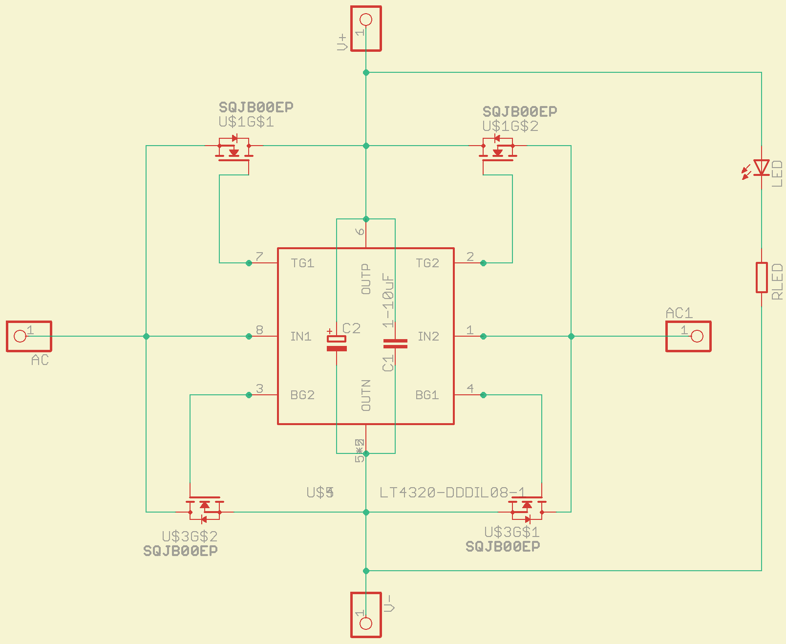
Schematic SMD LT4320 rectifier LT4320 based active rectifier
Schematic THT LT4320 rectifier LT4320 based active rectifier
Schematic LT4320 CRC PSU PCB: LT4320 based active rectifier
Edit 2: Revision in prices. (price drop!)
LT4320 based active rectifier
Edit 3: GB closed for SMD PCBs. Only last 10 pairs of THT pcbs remain.
THT BOM BY MERLIN EL MAGOO LT4320 based active rectifier
EDIT 4: New GB for LT4320 based CRC PSU PCB Started..PCB's Produced and being shipped..-Completed and closed...
1. The Design: LT4320 based active rectifier
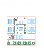
2. The PCB design: LT4320 based active rectifier
3. Physical PCB's: LT4320 based active rectifier
4. The BoM : LT4320 based active rectifier
EDIT 5: Group buy sign up has begun for modified SMD and THT rectifier boards with ENIG finish and earlier LT4320+CRC PSU PCBs. Please sign up at the below google sheet with your DIYA username and qty required against each pcb type.
LT4320 based active rectifier
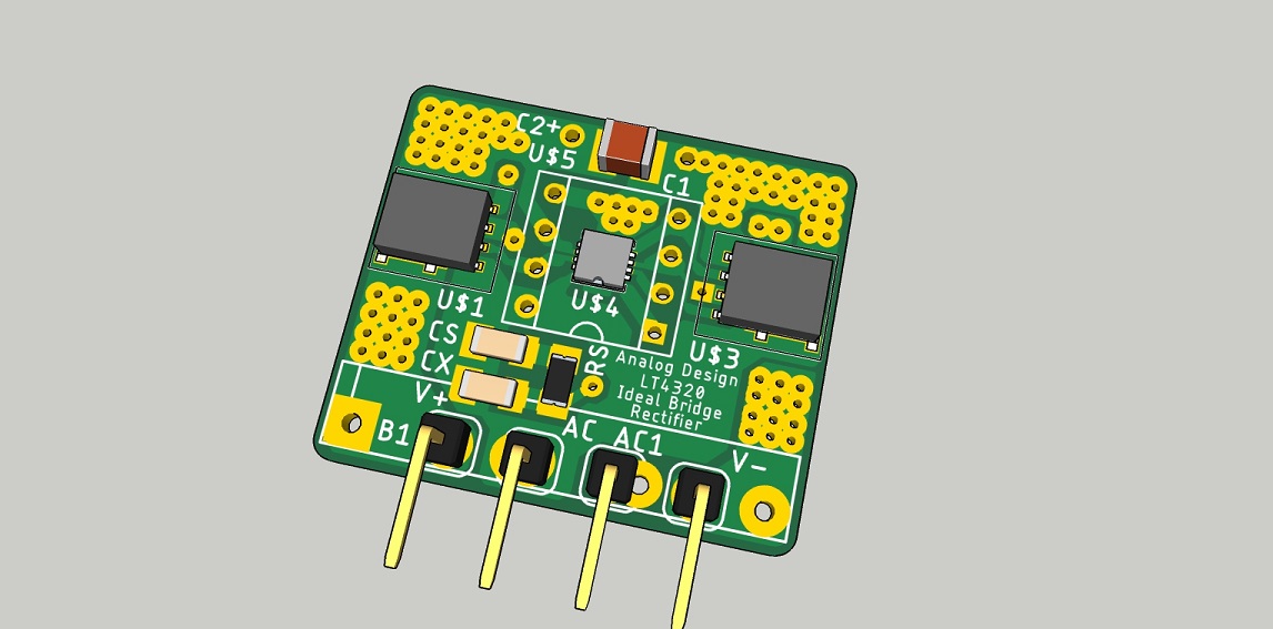
Some 3D views of how the actual PCB assembly looks like
SMD: LT4320 based active rectifier
THT: LT4320 based active rectifier
CRC PSU PCB : LT4320 based active rectifier
EDIT 5: HAVE ALOOK AT PAGE 78 AND 79 FOR ALL PCB DESIGN IMAGES, SCHEMATICS AND 3-D MODELS AT ONE PLACE.
here is something i have been working on for some time.
I am willing to offer the pcbs as a group guy.
let me know if there is interest.
I will share a bom to GB subscribers, all mouser based, if GB goes ahead.
regards
Prasi
Edit 1: Group buy closed for THT PCBs, but still open for SMD PCBs. More info in the below link.
Group Buy List
group list qty_new - Google Sheets
Schematic SMD LT4320 rectifier LT4320 based active rectifier
Schematic THT LT4320 rectifier LT4320 based active rectifier
Schematic LT4320 CRC PSU PCB: LT4320 based active rectifier
Edit 2: Revision in prices. (price drop!)
LT4320 based active rectifier
Edit 3: GB closed for SMD PCBs. Only last 10 pairs of THT pcbs remain.
THT BOM BY MERLIN EL MAGOO LT4320 based active rectifier
EDIT 4: New GB for LT4320 based CRC PSU PCB Started..PCB's Produced and being shipped..-Completed and closed...
1. The Design: LT4320 based active rectifier
2. The PCB design: LT4320 based active rectifier
3. Physical PCB's: LT4320 based active rectifier
4. The BoM : LT4320 based active rectifier
EDIT 5: Group buy sign up has begun for modified SMD and THT rectifier boards with ENIG finish and earlier LT4320+CRC PSU PCBs. Please sign up at the below google sheet with your DIYA username and qty required against each pcb type.
LT4320 based active rectifier
Some 3D views of how the actual PCB assembly looks like
SMD: LT4320 based active rectifier
THT: LT4320 based active rectifier
CRC PSU PCB : LT4320 based active rectifier
EDIT 5: HAVE ALOOK AT PAGE 78 AND 79 FOR ALL PCB DESIGN IMAGES, SCHEMATICS AND 3-D MODELS AT ONE PLACE.
Attachments
Last edited:
Hi Prasi,
Some questions, if allowed:
- Can you please elaborate on why this is interesting?
- Can it replace an existing rectifier bridge?
- How difficult is it to solder?
Some questions, if allowed:
- Can you please elaborate on why this is interesting?
- Can it replace an existing rectifier bridge?
- How difficult is it to solder?
1. minimal power dissipation, no heatsink for rectifier, higher DC voltage output for a given AC voltage, etc
2. yes, it is a drop in replacement for SIP-4 type rectifiers.
3. THT option for LT4320 provided, MOSFETs are SMD, but will be simple to solder for anyone who has soldered SMD's before.
regards
Prasi
2. yes, it is a drop in replacement for SIP-4 type rectifiers.
3. THT option for LT4320 provided, MOSFETs are SMD, but will be simple to solder for anyone who has soldered SMD's before.
regards
Prasi
I think more info on this is available here before it spun off onto its own thread. This version uses a double-die MOSFET. I can attest that this topology works very well - almost no heat, added headroom due to no voltage drop across silicon diodes, smooth switching with no noise spikes since phase is timed with zero crossing:
GB: CRCRC PSU
I am using this type of rectifier in the SLB PSU because of these advantages.
Nice little rectifier you are planning to make here, Prasi.
GB: CRCRC PSU
I am using this type of rectifier in the SLB PSU because of these advantages.
Nice little rectifier you are planning to make here, Prasi.
Last edited:
thanks x, yes, there will be some improvements for sure from tester ones, still working on them.
need to find some time.
need to find some time.
Hi prasi, do you think there would be more demand for your PCB if you made it using through hole components rather than SMT devices.
I assume you are trying to make it as small as possible.
I assume you are trying to make it as small as possible.
EYou could use 4 x TO220 MOSFETs with no heatsink. The LT4320 is already TH as an option. Just add a spot for 1uF ceramic x7r radial cap.
The SMT keeps package about same size as the monolithic bridges.
The SMT keeps package about same size as the monolithic bridges.
Last edited:

Subscribed. Would like to try this out. I wish the 4320 controller chip is cheaper though 🙁
Regards,
Regards,
Hi prasi, do you think there would be more demand for your PCB if you made it using through hole components rather than SMT devices.
I assume you are trying to make it as small as possible.
Hello Gary, let me try it with dual secondary , 2 of the LT , and 8 of the mosfets but it wont be a compact replacement for SIP-4 rectifiers; rather it will be a regular PCB that needs mounting holes, run wires to bulk cap PCB, etc.
regards
Prasi
I am running into the same situation in making an all TH PSU using the active bridge.
The use of TH components requires double the parts and the parts are large.
Here is an example of a 10A capable active bridge (just one rail):
Here is the layout for the TH equivalent (dual rail) - it takes up 20% of the real estate whereas the SMT version is a small fraction of that and can be mounted on underside:
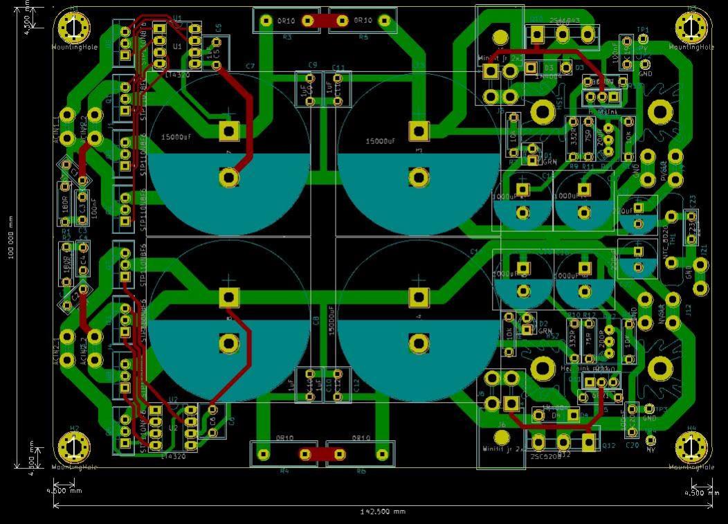
1. minimal power dissipation, no heatsink for rectifier, higher DC voltage output for a given AC voltage, etc
2. yes, it is a drop in replacement for SIP-4 type rectifiers.
3. THT option for LT4320 provided, MOSFETs are SMD, but will be simple to solder for anyone who has soldered SMD's before.
regards
Prasi
Yeah, the dual MOSFET is about the size of a smd opamp. Soldering should not be too bad. Using solder paste to stick the component to the board will help if you do not want to use regular solder. I prefer to use screw connectors than pins for AC though. Just curious what is the estimate of the current limit of the smd MOSFET. Thanks!
I have to agree with X and Prasi, using all TH components will increase the size (and cost) significantly. The 4320 is pretty expensive already 😱
Regards,
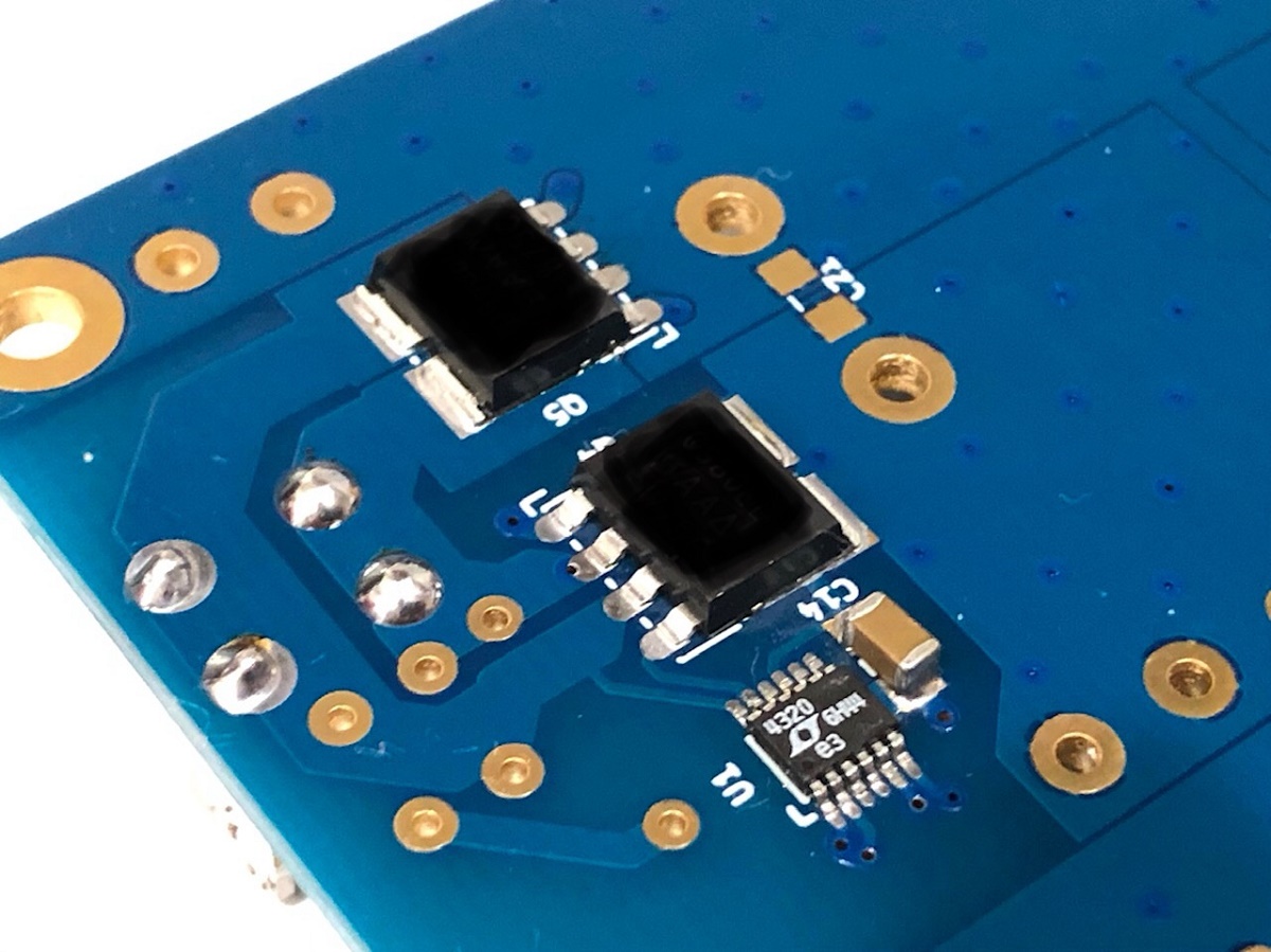
A Vishay-Siliconex SQJQ910EL (pictured above in the SMT implementation), can handle 70A, and up to 175C. Rdson of 8.6mOhm
https://www.mouser.com/datasheet/2/427/sqjq910el-1110892.pdf
Ohmic heating = 70A^2 x 0.0086ohm = 42W (within rating for part of 62W to 187W depending on how cool you keep it).
For use on a PCB with just conduction to the PCB for cooling I would try to keep under 3W of dissipation. That's about 19A.
These are tough little MOSFETs.
Thanks! X
Indeed, these are "powerful" MOSFET😀. You are talking about the smd version, right? Come to think about it, the size of the smd version of the MOSFET is only about 5 x 6 mm, 3 W dissipation is a lot for such a small device (please correct me if I am wrong) and there is no cooling. Is that OK?
However, I suspect that the typical current draw (for a class A amp running at 30 V) is probably under 5 A. So, the heat generated will be much lower.
Looking forward to your testing results!!
Regards,
At 4.35A they don’t even get warm. Direct cooling to PCB as heatsink can dissipate 1W to 2 mE no problem if there is more copper and vias to conduct heat away.
Hi prasi, do you think there would be more demand for your PCB if you made it using through hole components rather than SMT devices.
I assume you are trying to make it as small as possible.
Here is my all THT version of the rectifier, though small enough, its still cant replace the SIP-4 type rectifiers.
regards
Prasi
Attachments
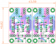
Here is my all THT version of the rectifier, though small enough, its still cant replace the SIP-4 type rectifiers.
regards
Prasi
Hi, Prasi
Looks good! Just curious, are there any special reasons that you put 2 "diode bridge" together on one PCB?
Regards,
- Home
- Group Buys
- LT4320 based active rectifier