Voice of Music 1428

Hi, I'm restoring a Voice of Music 1428 Tube Amp and found the incandescent power indicator is burnt out. The Sams schematic doesn't specify a part. Per the attached schematic it runs to the center tap of the 6 Volt filament transformer witha 10 ohm series resistor. Can anyone suggest a replacement bulb or LED combo for this bulb? Since this indicates power in a high voltage amp I want greatest reliability which may be an LED.


thanks
1686952259184.png


thanks in advance

Western Electric TA-7331-A Baffle

I kind of like the vintage look of this loudspeaker. A description is for example here https://electravolt.blogspot.com/2017/12/western-electric-ta-7331-baffle.html?m=1

I am now building a prototype of a large 3D printed horn for DCX464 and this style of cabinet would be a good match visually. Not so sure about performance, that is why I started this thread.

I see it as a sort of H baffle and I wonder:
  • how high would it be usable before getting some bad resonances.
  • how low would it perform with and without EQ
  • what would be the parameters required for a suitable driver and which of the modern PA drivers to use

I have Yamato YS-500 open back speakers with Eminence Deltalite 2515 and they measure almost flat in room down to 30 Hz when placed accordingly. So I would think the low end should not be a problem. I am more afraid of the front and back chamber resonances. I think the Deltalites could work fine even though the original driver was 12". I aim for the crossover to be somewhere in the 300 - 400 Hz range. Any comments will be appreciated!

Question regarding bias on my Conrad Johnson MV50..

I've owned this amplifier for thirty years now, and I've always used the bias led's to set the bias. I decided to buy a bias meter to check the level they used because I always got very short tube life and I was getting tired of the cost of replacing them. Well, when I checked the led's against the bias meter with brand new tubes, it was 55ma. Maybe I'm wrong, but isn't that a little excessive?

JVC A-X2 Super-A integrated amplifier - Right channel power transistors burnt

I´ve get an old JVC A-X2 Super-A integrated amplifier from a friend to be repaired. He said that one channel was burnt. When I tested the amp, the right channel has the two power transistors shortcircuited (both have B-C-E measured 0 ohms).

I've attached in this thread a picture of the affected amplifier circuit.

Also both R644 0.22 ohm 5W combined fuse resistors between emitters are open, and the same occurs with the R640 resistor.

I replaced all these components and put a proper fuse for my AC voltage (220 VAC) whose value was 2 A, and also connected headphones as a load to the amp. Loudspeakers are disconnected.

The original damaged transistors were 2SA1076 and 2SC2565 which I replace with 2SA1943 and 2SC5200, respectively.

When I turn on the equipment, the fuse immediately burns out. Then I mistakenly replace the fuse with one whose value was 5 A and turn on again. Immediately, the power transistors and resistors get in the same condition: transistors all have 0 ohms between B-C-E and resistors are opened, and the circuit get smoke.

I have tested all the circuit components and are all OK; all have the proper values. The only component that I've not tested was the IC602 (VC5022), the Super-A chip. I suspect that this IC is the problem.

What are the problem with this amp? Thank you all.

Diego

Attachments

  • Output stage.jpg
    Output stage.jpg
    156.6 KB · Views: 1,019

Alpha recording system model 4100

Hi guys.
I'm searching for a service manual (or at least a schematic) for an Alpha Recording System, model 4100. This is a high end music mixer, DJ style. A friend has one of these and will bring it over to me for repair. So far I couldn't find anything useful on the internet.
Any idea where to get the service manual for this apparatus?
Thanks in advance

AM Radio is disappearing

I took possession of a new Ford Expedition this week, the 2017 I have is nearing 150,000 miles. Still a great truck.

Low and behold, the 2023 Expedition still has AM radio, 2024 Fords won't. The reason -- Ford Motor Company can charge you $10/month for "streaming" iHeart radio and other services. These are complimentary for the first month of ownership.

The Euro imports (MB, Audi, BMW, VW and Vo.lvo) have already eliminated AM

Too bad. In the US 25% of the population listens to AM radio once per day

blocked by TI

I did want to ask a question on texasinstruments site and discover I am blocked, why? There is never something bad happening, I was sometimes
there for a technical question.

Maybe she think I am stupid and removed me.

Bad think people get so easely blocked on sites. I get slowly to hate the digital world more and more.

Attachments

  • ScreenHunter 2198.jpg
    ScreenHunter 2198.jpg
    24.7 KB · Views: 119

To PR or not to PR in a compact portable three-way.

Hi
I am setting off on a new build of a compact three-way mono battery powered dsp controlled speaker.
I have 2x SB Acoustics SB15NRXC30-4 for bass duty. They will be placed one on the front and one on the rear. Push-Push to cancel vibrations. https://sbacoustics.com/product/5in-sb15nrxc30-4/
2x Accuton P173 passive radiators. https://accuton.com/en-home/produkte/lautsprecher/hall-fame/Passiv-Strahler-P173
Scanspeak 10F/4424G for midrange in a separate chamber.
Scanspeak D2004/60200 for highs.
It will be powered by a 6S Li-ion battery and a Zoudio AIO438 4x 38W dsp Bluetooth amp. https://zoudio.com/product/aio438/
The internal volume without drivers will be circa 10 litres.

Before I begin I want to check the design principle, and I have come across a thread questioning the need for the passives. One person suggested that they would only boost around the tuning level 1db but would help with excursion and power handling.

I have all drivers in hand and a pair of the passives from a previous project.

As proposed, the passives are going to be placed on the sides of the cabinet (a square tower).

Thoughts?

Linn LK100 Power Amp schematic wanted please.

I've just purchased a LK100 from the usual auction site and in anticipation of some capacitor upgrades being needed, the schematic would be handy, as well as interesting from a circuit topology standpoint.

I'm new to Linn products and can't find any service or upgrade sites online.

I believe most components are smd (apart from output transistors) so maybe only the psu caps could be replaced.

I am using a Quad 306 currently so it will be interesting to compare them.

sub bass system

Hi All


I had build a subwoofer some time ago where the speaker do point to the floor and spread around, because it did act as a slot.
I have change some things.

Have set wood parts in so the opening is not the same enymore but gradual widening around from wide to small. So I get no more strong notes on
frequencies who match with that slot.

Now bass higher region is clean, no boom enymore, the box go without active filter as low as 25 Hz and stops on 100 hz not bad for this small one.

Attachments

  • DSCN5317.JPG
    DSCN5317.JPG
    366.8 KB · Views: 88
  • Like
Reactions: GM

Same drivers in different box sizes, yet both give positive results!

Hi, I discovered two speakers using the same drivers and crossovers. But different box sizes. Yet they both provide good sound.

They are ADS L810 and L1230. As mentioned above, these speakers have the same drivers and crossovers but different box shapes and sizes. They received many positive reviews. Many audiophiles will know, especially in the US.

How could it be? Does this mean their woofers were designed to perform well in various box tunings?

Does anybody know of a ready made six channel PGA2311 kit for control by Pi, ESP32 or Arduino?

I need a way to control independent volume to the active subs and the two power amps on my boat. Main volume will still be the headunit. I have seen lots of prebuilt PGA2311 kits on Aliexpress and eBay with IR remote controls, but IR control is slow and imprecise, when the IR signal has to come from an ESP. The volume control will be in a sealed IP67/68 box under the dashboard. The main thing is that I must be able to reduce volume on the subs almost instantly, when running playlists and something with too much bass comes on that makes them distort and can damage them. So does anybody know of such a kit where I can program the controlling unit to "jump x dB down" and then fine tune it after that?

Here's an example on the IR remote type:
https://www.aliexpress.com/item/1005005548879854.html
I assume that it's not possible to hook up a Pi, ESP32 or Arduino to that. I would prefer Pi or ESP32 control, since I have never worked with Arduino, but if Arduino is the only option I will try to find out how I do it with that.

Also I am not good enough to solder to use a kit, I manage to replace keys on my Matias Ergo Pro keyboard (they are quite regularly worn out), but that's as far as I can go with my tools and hands.

This is one of the two possibilities I have, I am also going to see if I can use USB sound cards, Pi's and CamillaDSP for this, but I want to test the two solutions against each other and see what works best.

Active Speaker Powers on but No Sound. Replaced transistors

I have a Hybrid PB 15" Active Speaker.
It has 2 input xlr channels and a Speakon Amp out port.
The speaker blew due to an electrical surge. I replaced the fuse, Replaced all 4 transistors (2x A1941 and 2x C5198) I replaced 2 R100 resisters (brown black brown gold) but still no sound. I also replaced 5W 0.20 ohm resisters.

Speaker Powers up but the Relay does not click. If I connect a audio source into the speaker the speaker does not play but if I connect another powered speaker to this speaker using the line out port , the connected speaker plays which means the Inputs are fine and the output line out is fine but the Speakon Amp out doesn't play or power an external speaker and the internal sub and tweeter don't play.
Capacitors don't look popped.

What else can be causing the relay not to even start up.
Hybrid does not release the speaker schematic to the public.

Attached is a image of what the board looked like when the 2 resisters blew (R100 brown black brown gold) and the second image is what the amp board looks like.

Attachments

  • 1.jpg
    1.jpg
    4.9 KB · Views: 246
  • 2.jpg
    2.jpg
    4.9 KB · Views: 230
  • 3.jpg
    3.jpg
    37.6 KB · Views: 272

Unison S8

Hi I am in need of some help repairing a unison s8. The symptom is the front end valves, 3 of, do not light. The output valves do light. I could use a circuit diagram but unison won't supply one, henley services the company that supply's and provides repair work on them do not appear to help and just won't me to send it to them. My friend who owns the amp is against this as the amp is over 20 years old and he afraid it might get damaged in the post. He is also afraid it it might be more expensive then he can afford. Iam sure with a circuit diagram I can fix it. Can anyone help. Many thanks Cliff.

low power output audio board recommendations

Hi Thanks for reading. I want to build a low power amp. I am currently using a modded quad 405-2 with help from a thread on this website. At 200 watts output the quad does sound good but is way too powerful for me. I have tried the tpa 3211 and tpa3255 chips but these were a considerable step down from the quad

Do you know of any board that can output about 20 watts or so, with good sound quality, not class a please

eBay 300B PC board kit

I ran across an interesting 300B kit on ebay.

Without tubes or Iron it is $69.99.

HiFi 300B Vacuum Tube Power Amplifier Board DIY KIT Class A Stereo Audio Amp 16W 832681726807 | eBay

There are several other sellers with the same board/kit. This is the only one with a schematic.

The circuit board does not match the schematic as there are two bridge rectifiers on the board not shown in the schematic, as well as the filament supplies missing for the 300Bs.

There may be other mistakes as well.

I will trace the PCB when I get it and make a schematic in LTSpice to post.

The Grid Stops on the 6SN7 can be increased.

The tube set is listed as PSVANE 300B+Russia 5U4G+Russia 6SN7, however the symbol for the second tube is not a 6SN7. I suspect this is a mistake as the tube sockets are two 4-pin, three octal.

I plan to build it as-is when I get it, then experiment with changes once it get any bugs out of it.

There may be a serious design flaw as there are only two 5Vac connections. It should have three, one for the rectifier and one for each 300B.

Transformers will be XPWR105-120 (EDCOR), three Triad Magnetics F7-X (5V 3A) and One ELectron UPT-3 output. The choke will be a Triad 200mA 5H choke.

Steinway & Sons Streaming: An Excellent No-Cost Music Source

Just a reminder, or if anyone does not already know: Steinway & Sons Recordings makes their entire music catalog of more than 100 CDs available for FREE streaming listening (no registration required and no personal data requested) here:

http://steinwaystreaming.com/steinway/streamHome.jsp

Of course, if you have Qobuz, you can hear the same music in hi-res, which Steinway Streaming is not.

But it's a great no-cost way to explore new music and performances. The most recent CD is quite a Coup for Steinway: Yunchan Lim's "Live from the Cliburn" Liszt Transcendental Etudes.

(Steinway sells a boxed set of my Christmas string quartet CDs, but I do not receive any payments of any kind in respect of those titles.)

I put together a list (with links) of 13 albums that I think most listeners will enjoy, ranked from greatest general appeal to greatest specialist appeal, with capsule reviews:

https://thetannhausergate.com/index...-streaming-an-excellent-no-cost-music-source/

ciao,

john

Bandpass Effect of ports?

Is there any information of the band pass of effect of speaker port. The one band pass sub I've owned claimed to drop off @6dB octave above 200hz. I'd assume the sound coming from the port of a normal vented sub would offer similar low-pass characteristics.
Tuning frequencies being equal is this filter slope affected by other port characteristics?

e.g. if an 80 x 125 and a 50 x 280 port offered a tuning frequency of 50hz would the high-frequency filter effect be the same? Is it always 6db per octave ?

TDA8954J Yorkville YX10P repair

Hello, I'm no electronics expert but I some knowledge and tools to repair such things. Anyhow I was given a Yorkville PA system from a friend to have a look at and apon inspection I found 2 blown fuses after the transformer and also found the tda8954j with burnt pins 14, 15, 16,....see photo. I managed to get a replacement ic and soldered it in. Replace fuses and test. The system powers up no fuses blow. I do have audio now at the speaker but it's very poor sounding...also by using my finger to check temps I found the tda8954j heating up quick...any suggestions?

Attachments

  • PXL_20230607_173545392.PORTRAIT.ORIGINAL.jpg
    PXL_20230607_173545392.PORTRAIT.ORIGINAL.jpg
    464 KB · Views: 109

Unison Research S8, let's build it!

Hi everyone,
look what I found....the unison research s8!

unison audio s8 845 single ended tube amplifier,octal 2a3,el34,ecc82,ecc88,kt88,300b,845 direct heated triode,mkp, ...

So..I posted the schematic. Now, is there anybody out there that can help me build this sweet jewel?

I'm not an expert in elecronics, so I'll build it with my uncle, but I need some help on finding all the needed pieces.

I was told by someone who knows a lot about tube amps to use a 5687 alimented at around 550v to drive the 845.

Ervin

ps. could please someone who knows how to do it rewrite the schematics on the computer?

Adcom GFA 555ii with high dc offset on one channel (V-)

Bought this broken GFA-555ii several months ago and the symptom from the seller was no sound on one channel. I checked and the fuses where missing from the DC rails for that side. Installed new fuses and powered up on DBT with no load connected. V- voltage present on the output. I refer to it as V- for the duration of this post because I'm testing this powered through a DBT which will drop the mains voltage some, so instead of the +/- 80V rails, they're more like +/- 60V.

I started probing around on the input and output assemblies looking for obvious failures. All of the output transistors on the bad channel tested fine in situ when checking for shorted outputs. The only failed component that I found was one of the VAS transistors on the input board, Q157 was shorted E to B. I went ahead and replaced all of the VAS transistors on that side with the following subs (2sa1210 -> ksa1381, 2sc2912 -> ksc3503). Powered it up on DBT, still V- present on that output.

I then started looking for other failed components in the vicinity that might be bad but so far haven't found a smoking gun.

Additional things I've done or checked:
  • Replaced diff pair (2sc2362->ksc1845) and made sure they were tightly matched. Diff pair actually tested fine once removed from circuit
  • Replaced C154 (4.7uF 50V) with new. Cap wasn't bad but had 15ohm ESR
  • Cleaned 2k trimpot, but haven't yet verified it sweeps cleanly across resistance range
  • Checked driver transistors on output boards out of circuit, all measured good
  • Checked thermal transistor on output board out of circuit, measured good

Measurements from around the input board
OpAmps
PinIC101 (Good Channel)IC151 (Bad Channel)
2 (- input)0.06V-0.51V
3 (+ input)0.05V-0.42V
6 (output)12.19V0.012V
7 (vcc)19V19V

Input board pins/test points (powered through DBT)
Pin (Good Channel)VoltagePin (Bad ChannelVoltage
51.78V7-57V
6-1.78V8-57V
1157V1357V
12-57V14-57V
160V180V
171.1V190.01V
22-57V24-57V
23-57V25-57V

Thermal Transistor (transistor tested good out of circuit)
Pin ColorJ101 (Good Channel)J151 (Bad Channel)
orange-1.1V-57V
red1.7V-57V
brown-1.7V-57V

I'm starting to wonder if the opamp is bad, but I don't have any way to test it out of circuit. It doesn't blow the rail fuses or draw an abnormal amount of power as long as there is no load. I don't plan on connecting a load until I resolve the high offset issue.

Looking for any feedback on further debugging steps. Thanks so much for the help!

pboyz needs help identifying unmarked IC C12,V1 IC chips

pboyz 16000 needs help to identify unmark ic c12, and v1 ic chips please see the pictures below

Attachments

  • 0-02-01-9a002b2d7b948fb7633ad6c4b88df2437c106c85d75435627f5b96a72002fd55_671f445f9169725c.jpg
    0-02-01-9a002b2d7b948fb7633ad6c4b88df2437c106c85d75435627f5b96a72002fd55_671f445f9169725c.jpg
    233.5 KB · Views: 90
  • 0-02-01-b540871a5b5960d745650037550139ba8efc248341af8cb2af9b9ac2bb70524a_631447f4e2ed2911.jpg
    0-02-01-b540871a5b5960d745650037550139ba8efc248341af8cb2af9b9ac2bb70524a_631447f4e2ed2911.jpg
    198.6 KB · Views: 91

Linn Axis Motor

I have a Linn Axis which needs a new motor as one of the windings is open circuit. There seem to be many types of motor on ebay but none refering to the Linn Axis, only the Linn LP12.
What is the voltage required is it 240V or 110 Volt. For UK frequency is 50Hz and revs 250rpm. The axis motor has three tags rather than flying leads but that's not really a problem as they can still be connected. Are LP12 and Axis motors the same spec?
I have replaced all the capacitors on the drive board and managed to release the motor with a hot air gun. I would appreciate any help regarding sourcing a motor.
Thank you

Mid-bass: Expensive high-power vs inexpensive drivers

When we go up in price range, drivers usually get more fancy looks, larger coils and magnets for higher power handling and longer Xmax.

Just compare the cheap looking thing on the left to the 20 times more expensive luxury item to the right:

1686552784656.png


Are expensive drivers always better? I'm not so sure...

I will set my design goals first :
  • Four 12" drivers
  • Used for mid-bass, 100-500 Hz
  • Line-source
  • Open baffle or closed box
  • Required SPL 100 dB @ 3 meters with less than 1% distortion

(And EQ is available)

Extreme input power or cone excursion is not required to meet these goals. So why pay thousands of US$ for 1000W drivers with long Xmax, when far less expensive drivers can do it?

The thing is that I was rather surprised how well an inexpensive driver like Eminence Delta 12A performed as mid-bass driver compared to drivers costing many times more.

power supply for phono preamp board and ADC board (rca in, spdif out)

I am trying to simplify my setup while switching to DSP crossover with no analog input (minidsp flex).

I have a cheap ART DJ phono preamp with 9V brick and I am looking at this audophonics RCA to spdif board (5V in):
https://www.audiophonics.fr/fr/modu...1804-rca-vers-spdif-24bit-192khz-p-17047.html

Idea is to put these two boards in the same enclosure with a psu (240V in) with two output: 9V DC and 5V DC.

Signal wise: two RCA in from the turntable in the phono preamp, two RCA out to the ADC board and a SPDIF out to the minidsp as a "digital" source.

Two questions:
  • is the proposed "lego" electronic build ok? Anything I should be looking for?
  • how to build this PSU? Most smps don't have two outputs. Is there an easy way to do this?

Thank you!

Need Help With MJ Acoustics Subwoofer

Hi Guys,

I'm struggling with a Subwoofer MJ Acoustics MK II Pro 50.
Initially I had issues that subwoofer would not turn on the print fuses where burned and was caused by overheated Mosfets IRFP240 and IRFP9240. So I replaced those while I was not sure if there where issues with the large capacitors I replaces them both just to be sure.

So i thought to be back in business however Sub goes on and no issues but when I plug in the LFE is starts making loud noises and there is no audio.
Not sure where the issue comes from.

Also when I tur the knobs of the High level input it also goes crazy while i'm not using the High input

All the help appreciated.
Cheers,
Hemant

transporting drivers (magnets vs hard drives)

i generally commute on my bike to my studio / workshop, usually bringing my laptop + couple portable hard drives in my backpack. whenever i have to transport drivers from home to studio im afraid of getting these magnets to close to hard drives so i end up using another bag.. . am i being paranoid? most of the speakers im working with dont have huge magnets (4"ers) but curious if anyone has a story to tell 🙉

2-way bookshelf with aluminium cabinet

I have a pair of aluminium square section 150x150mm and 530mm high, 3mm, which I want to make into a bookshelf speaker around 10ltr. This is an available size (6.5x6.6inch) so anyone could build it. Hole saws for the cutouts and I reckon on attaching top and bottom plates with 4 thick bolts going through the cab.

Question is how to treat the cabinet for resonances. Some kind of CLD is possible - e.g. bolt on two birch ply sides with something like green glue, rubber, vinyl, bitumen or whatever in between.

What would you do?

listening to LoFi

hi all - just a general query - ive been listening alot recently to a fantastic record ("V" by the unknown mortal orchestra) which is decidely "lo-fi" in its recording aesthetic; fuzzy, warbled, saturated, fat low-end. it took me a while to hear past the "lofi-ness" and to hear just the music. since then it doesnt bother me that much.. but as someone who is occupied with speaker design and building it was an interesting exercise to hear past a non-perfect recording.

does anyone have a strategy or specific approach to listening to lofi music on hifi systems?

LED wiring for power indicator

Like most of us, I usually prefer to let tubes do the talking and show that an amplifier is ON.

However I am currently finishing off a project in which the tubes are enclosed in the chassis, so will need to use a resistor + LED combination and 'steal' the power supply from the filament power supply.

Apologies for the crude drawing, can anyone confirm that wiring it like this is the best way to ensure no noise is injected into the system? I have seen some folks wire the LED in series with a heaters, but that doesn't seem smart in the event of the LED failing.

blue LED.jpg

Adelphos Build log

Thanks for the amazing community. After a few years away from the audio world, I wanted to get back into full room sound, not just listening on headphones. I've been lurking for months and really appreciate the insight and help so far! I'm a hobbiest woodworker, so building a kit sounded perfect.

I've got the Adelphos on order from Meniscus, and decided this weekend to start building the cabinets.

For fun I only wanted to use scraps from the shop. Luckily I've got a lot of scraps.

First step, cutting up 18mm baltic birch into too many 1 1/16" strips

IMG_0130.jpeg


Here's all the strips before gluing

IMG_0131.jpeg


The adelphos calls for a 8.5" wide speaker, with 3/4" material - 7" internal. Turns out 10 strips glued together is 7" 1/16 - close enough!

IMG_0134.jpeg


I doubled up some glue-ups since I didn't have that many clamps. Wound up using 20 clamps, of course just proving you can never have enough clamps.

After letting the glue dry, I scraped then thickness planed the panels down to 1" thickness.

IMG_0141.jpeg


Next, I made up the panels for the sides. Had a few nice boards of walnut to use up.
IMG_0142.jpeg


I don't have a jointer so after cutting the boards to rough size I did a quick jointer jig and edge jointed all the boards.
IMG_0143.jpeg


Then I glued up 4 panels, no pics of that, it's boring.

Thinking I may miter the top/front/bottom/back box. Did a test by cutting two of the BB panels, domino for alignment.
IMG_0145.jpeg
IMG_0147.jpeg


And this is why I test! You can see the domino wasn't setup well and cut all the way through in a few spots. Will use 4mm for the final, not 5mm x 30.

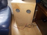
Here's a mockup with the walnut panel placed on it

IMG_0148.jpeg


That's when I noticed the corners aren't aligned the way I expect. Here's a macro shot of the bottom of the miter:
IMG_0150.jpeg


After some headscratching, it turns out my cross cut sled is REALLY not square. I have no idea how this happened - it's seemingly been good for a while. But it's also loose and wobbly, not square even to itself anymore, and frankly I'm questioning if I ever made it work in the first place despite having dozens of projects on it. oops.
IMG_0151.jpeg


I think this is all I'll get done this week. Next weekend I'll make a new sled, then make the miters, test it out again. Hopefully the drivers arrive soon and I can start cutting out the holes for them.

Carrera vs Adelphos

Trying to decide on what to build next. I’m thrilled with the Piccolos I built, but need to move them to another room and build something else for my music listening room. It’s small, only 11’x 12’, and has thick carpet. The Piccolos sound great, but I’m ready to have something a little larger to replace them.

I’ve narrowed it down to either Paul Carmody’s Carrera or Jeff Bagby’s Adelphos. They both fit the bill just right in terms of physical size, power expectations, and cost. And both use high quality drivers with crossovers and tuning done by expert designers.

I listen to classical music and opera. Not much of anything else. So what is really important to me is low distortion and dynamic range. Particularly the later. Some people think that it doesn’t matter what kind of music you listen to, but I think it does. A Mahler symphony requires far more dynamic range than a jazz ensemble or singer. And the speaker must be able to deliver it in order to enjoy the music.

The other thing I'm looking for is to get as large a sound stage as possible. Not sure that there will be much of difference between these two, but would be interested to know.

I think either of these speakers will perform very well with classical music, but am still looking for some reason to choose on over the other. Would appreciate any useful comments. Particularly from someone has heard these and has an informed opinion.

For Sale Altec, Lowther, and Klipsch

Altec 515Cs (Great Plains Audio) - 16 ohm ($1,675 shipped to CONUS)

New in box Altec 515C drivers from Great Plains Audio. These are the 3rd and 4th drivers built by Bill.
  1. The drivers have been stored in a dry, non-smoking Colorado home and have never been installed. We "swept" them from 20 Hz to 1KHz to ensure there's no voice-coil rub.
  2. The slight scuffing on the label of s/n 1113-0202 is how the driver was delivered.
  3. These will be double-boxed (and of course, enclosed in plastic) to ensure safe shipping
If you've had your eyes on 515C's, know that the current price at Great Plains Audio is $2,900 per pair (plus shipping). Check eBay for comparison (how great a deal this is).

The Azzolinas have sold, so I removed them from this post.

Thanks for looking!
Thom (more photos on the web page above, but scroll down for a few)


bb-altec-515-both.jpg

bb-altec-515-201-01.jpg
bb-altec-515-202-01.jpg
bb-altec-515-201-02.jpg
bb-altec-515-202-02.jpg

Should the mid driver have less sensivity than the bass driver (Harman curve in mind) ?

Hi,

How to choose the sensivity of the mid driver when having already the bass driver and wanting a sligthy diving spl magnitude à la Hartmann (Toole book) ?

There is the baffle step to think about. OK. But at seing such measurement -look at the picture with the overlapp of the 3 drivers- The midrange seen to need less spl orat least needs atenuation vis à vis of the bass driver overlapp : look at the green mid curve which seems to be circa 7 to 8 dB less than the end of the bass driver !

1687164517669.png


Here it is a Pida's member design just for illustration.
For the discussion : imagine I have for instance a Bass driver measured on its baffle around 91 dB/2.8V around 300 hz where I want cross over with a mid ! Which sensivity at minima should I select the mid driver ? Around + 3dB for the bafle step compensation or less than the bass driver in that 300 hz aera like in the picture number 4 above in order to have a sligthy diving curve and/or maybe try to avoid serie resistors ?

Forget it all and choose the mid sensivity sligthy equal to the 300 hz bass aera measurement at 1 m ?

Thanks for your thougths

AD9220 A2D confusion.

I have a new USB scope design using an AD9220AR or AD9220ARZ.
These are SOIC 28 pin parts.
The SOP 28 parts have a "s" in the name like AD9220ARS and AD9220ARSZ.
The SOP versions have pins on half the pitch of the SOIC so its imprtant I get it right.
Pretty much all the cheap Chinese vendors have the IC's marked wrong.
They are mostly selling AD9220AR and AD9220ARZ as SOP !
I managed to get a correct one from RS Components but at £20 a pop not viable for a production run.

Simple AC Heater - 6c33c - failing

My monobloc amps each use 3 x 6c33c, two with a single triode heated, one with both triodes heated. A 12.6V 6.6A transformer is directly wired to to the three tube sockets such that all the 6c33c heaters receive 6.3vac or thereabouts. The amps have many thousands of hours on them and a couple of years ago I had a heater transformer burn out and the AC wiring began to melt the insulation. At the time I put it down to a 6c33c failing in such a way to increase the AC draw (i.e. a short circuit) thus causing things to get hot and eventually fail. No fuse on the heater circuit...everything direct wired. Replaced transformer and wiring and set to listening a lot more.

Today, this has happened again (with probably another 6,000hours on the amps in the meantime) about six hours into the days playlist and I believe it is more than bad luck with a tube failiure, it is now a design flaw. But I am having trouble trying to figure out why this is occuring.

Filaments are floating although the transformers are centre tapped so could be elevated if necessary. The 6c33c plates are 200V/240mA and 190V/150mA depending on whether the tube has one or two triodes heated. Cathodes are directly grounded (no caps or resistors to ground) and the amp uses a 150V bipolar supply to generate an adjustable grid bias (and eliminate the input capacitor). See attached snippet of schematic. In the schematic Dark Blue is signal positive (+150V from bias supply), Light Blue is Signal Ground, Dashed Light Blue is connected to 0V in the bipolar bias supply, Signal Ground, Green is -150V bias, Dashed Green is connection to chassis ground, Red is B+. The 6e5p's have a heater supply separate to the 6c33c.


Snippet of Schematic.png


This is not quite your normal SET amp arrangement but the sound is glorious, so when repaired I would like it to not fail this way again so am calling for help. Any ideas for why this amp melts heater wires from time to time?

Attachments

  • Snippet of Schematic.png
    Snippet of Schematic.png
    33.1 KB · Views: 97

AI And Amp Voicing

I work in IT. While I have no formal experience with AI, butI understand its ability to quickly comb through massive similar data sets to determine patterns.

This evening, I watched a couple YouTube interviews of Papa. Their content got me to reflect on the various pieces he's authored concerning amplifier voicing. In particular, I enjoyed the explanation of negative 2nd order harmonics which accompanied the Korg NuTube B1 piece.

I've built the Aleph-J, F6, M2, and F2J (in that order), and have become familiar with their different characters (though I wish I had a wider variety of speakers to sample them with). I imagine Mr Pass spent a considerable amount of time developing each of these characters.

I began to wonder if AI could help us better understand which amplification artifacts (or lack thereof) are going to sound "better". I'm not sure what the data sets would be. Perhaps a combination of topologies, measurements, reviews, and sales figures?

While we can't yet measure the processing happening between our ears, maybe we can analyze more data to better understand why some of what makes it through is more pleasing that others. Or, maybe it's just too subjective. My nirvana is an M2x/Ishikawa driven by a Korg B1. Someone else's might not be. But, perhaps there's similarities between the two that are an important data point we haven't yet paid attention to.

My point is that I wonder if we'll get to a point where measurements could conclusively indicate how pleasing most people will find a particular amplifier within a certain application.

Just my musings, anyway.

Marantz Basic Amplifier aka Model 2

I Have a single Marantz Power Amplifier later known as Model 2. It is my understanding that there were at least three model versions of this particular amplifier
1) Marantz Power Amplifier
2) Marantz Model 2
3) Model 2a
and posibly a Model ( 2b?)

Is this correct? If so how did the variations differ?

Are there any Marantz Mono Tube amp experts here? I know Eli Duttman and Jim McShane are HK Citation 2 fan/experts. Hopefully they, amongst others ( Tom Bavis ? ) can help me decipher the supoposed design differences.

In the example I have, it has a blue colored selenium rectifier marked RS065Q manufactured by the International Rectifier Corp. My concern is that the Rider Manual doesn't list peak current (not available? according to the listing) I found its specs here https://worldradiohistory.com/BOOKS...tifiers-And-Crystal-Diodes-Theodore-Conti.pdf

So how do I come up with a suitable silicone diode/resistor replacement for it? Anyone have any experience with this particular Selenium and know what it can and should be replaced with? The schematic is no help as it only lists the selenium as S.R.1 (sELENIUM Rectifier 1) see schem attached

Scant information out there on this very rare amplifier and I want to be dead careful in restoring it before I do a dim bulb test and if good power it up slowly and incrementally.

The tube complement seems to have been consistent throughout its 3 or 4 year manufacturing run, consisting of 2 X EL34/6CA7 1 x 12AX7 1X6CG7 and 2 X 6AU4 (Damper Tubes?)

I have replaced all the tubes w/known good ones except the test failed 6AU4 tubes. What was the purpose of the damper tubes? Haven't run acrosss this implementation on HK, Scott, Fisher or English stuff of the same period.

Thanks alot.

Len

Attachments

  • rectifier.PNG
    rectifier.PNG
    47.7 KB · Views: 386
  • rectifier2.jpg
    rectifier2.jpg
    130.7 KB · Views: 378
  • rectifieer4.jpg
    rectifieer4.jpg
    108.7 KB · Views: 425
  • rectifier5.jpg
    rectifier5.jpg
    96.6 KB · Views: 438

  • Locked
pboyz needs help to identifying unmark IC C12,V1 IC chips

pboyz 16000 needs help to identify unmark ic c12, and v1 ic chips please see the pictures below

Attachments

  • 0-02-01-9a002b2d7b948fb7633ad6c4b88df2437c106c85d75435627f5b96a72002fd55_671f445f9169725c.jpg
    0-02-01-9a002b2d7b948fb7633ad6c4b88df2437c106c85d75435627f5b96a72002fd55_671f445f9169725c.jpg
    233.5 KB · Views: 95
  • 0-02-01-b540871a5b5960d745650037550139ba8efc248341af8cb2af9b9ac2bb70524a_631447f4e2ed2911.jpg
    0-02-01-b540871a5b5960d745650037550139ba8efc248341af8cb2af9b9ac2bb70524a_631447f4e2ed2911.jpg
    198.6 KB · Views: 88

Kenwood hum

Hi I have a issue with my 1977 Kenwood Ka-7100 with a Fluance Rt-85 turntable. I bought the amp fully serviced. Caps replaced and a few noisy transistors replaced.
The sound is amazing below half volume. Around 6 or 7 I get a pretty loud hum/feedback like a bad ground?
I thought maybe it was my ac line in my house so I bought a cheap line conditioner from amazon. No help.
The amp still has the 2 prong power chord.
I have a few new 180 gram albums with very little hum. But older original albums seem to be more prone to the hum.
Where should I start?
Thanks

Two Transformers same mains line help please

So Ive decided to go toroidal for my PSU for my soon to be DIY amp- I am fresh meat new know basically nothing. I found a transformer with proper V and A i need 40V 5A X2 so I can power two boards with it.. But I am having four boards in one chassis- 8 channels of amplification total.

I have seen many multichannel amps with this set up of two transformers- so can someone help an idiot out and explain or show how to do this simply. If i could find one that was 40V 5A with 4 outputs id just use that to make it easy but I haven't yet and im on a budget,

https://www.antekinc.com/as-4440-400va-40v-transformer/

How do you calculate enclosure size with passive radiator?

I feel like I've looked everywhere but can't find an answer to this. I think I saw somewhere that the volume of the enclosure would be the same as that of a sealed enclosure but adding a little extra to make up for the volume taken up by the PR. is that right?

I'm asking this question as a followup to an earlier post. I just posted another question there but I may as well ask it here too. I'm converting an old radio to a bluetooth speaker so I have to build an enclosure that will fit inside of a 13.5x7.5x8" space. Based on that size do you think I could go three way mono with a port or PR on the sub, or will it be better to go two way mono with a port or PR on the full range?

John Marks' Bookshelf for Lovers of Recordings (a/k/a, my "Tracking Angle" Debut!)

1 Fabulous Phonograph.jpg


I got inspired to compile a list of books not about music per se, but rather on the subjects of:

1) The history of recording technology;

2) The history of the record business; and

3) The interactions between recording technology, the record business, and the art of music.

And example of what I mean by No. 3 is the fact that the change from carbon microphones to piezoelectric crystal microphones made "crooners" such as Rudy Vallee popular. Another example is how the short running times of 78 rpm discs influenced jazz.

The plan is for Michael Fremer's "Tracking Angle" to run a review of one recommended book per week for 12 weeks. That's more than 4,000 pages of reading.

The first installment does let all the cats out of the bag, btw--the whole list is there.

https://trackingangle.com/features/john-marks-bookshelf-for-lovers-of-recordings

If I had to recommend one book for everybody to read, it would be Amanda Petrusich's "Do Not Sell at Any Price." But if that subject matter (original Blues 78 rpm discs) does not interest you, "Goodnight LA" is wonderful.

All the books are wonderful, in fact.

Thanks to Michael Fremer for hosting it.

john

Help/Advice converting a 572B amplifier to a 211 based amplifier

Hello,

I own 2 wyetech Topaz amplifiers, both stereo. The first one I got was based around the 572-10 output tube, after 10 years I blew an output transformer. This lead to Roger (amp designer, since passed away) telling me about a 211 topaz with the same issue as mine, a bad output transformer. I acquired it and Roger thought it best to take my good 572 output transformer and move it to the 211 chassis as the 211 sounds better and it is a much more long term reliable tube. Last week I opened the 572 chassis to look at the circuit and noticed that he changed the HV PSU for even better filtration and really made some very positive changes on the 572 tube filament circuit adding much more filtration. In fact on my current 211 filament circuit I measure 52.7 mVac at the filaments and when I fired up the filament transformer for the 572 I measured 3.3mVac at the filament. Hence I feel converting the 572B amp to a 211 amp is a worthwhile project. I am skilled as to physically working on this amp and very careful around the very high B+ and Driver tubes PSU's. I am NOT a knowledgeable tech, just a experienced hobbyist.

Looking at the circuits of the 2 amps, other than the HV PSU circuit, the circuits are pretty close to each other and the HV of the 572 only differs in that he used 3 large ASC propylene in oil caps vs. 6 solen metalized polypropylene caps in the 211 HV supply. Both amps put 1200Vdc on the B+ line, both amps use the same 10K primary output transformers, both amps put 450Vdc on the 6bx7 driver tube and 400 Vdc on the 6sn7 input tube. The input/output board components are almost exactly the same for both amps with only a few minor changes that should not matter, I believe. (bypass cap of 1uF vs .53uF, bypassing the 470uF cap), 470uF cap on the cathode of the 572 vs 500uF on the 211, 200K resistor from input to ground on 572B and 79K resistor in same spot for 211 amp.

So to change this amp from a 572 to 211 amp I think all I would really need to do is 1) change the power triodes filament toroidal transformer to one that can supply 10Vdc and 3.5A on the filaments of the 211 tube vs. 6.3 Vdc and 4A for the 572 filaments. 2) change the power tube sockets from 572 to 211 tubes.

I will also need 2 new output transformers for this amp, without going crazy cost wise I am thinking 10K transformers from either Hammond or Edcor. The amps originally had audio note uk transformers. Wyetech changed the output transformers on his Ruby amps (created after my topaz amps) to Hammond so I'll probably go that route.

The serial # of my current 211 amp is 9, the 572 amp is 28. Based on my observations Roger learned more about PSU circuits as he built amps the 028 has a better PSU circuit than 009. If the conversion works as I expect then some day I may pull the uk audionote output transformers from the #9 211 amp to the now converted #028 amp. For ultimate sonic bliss.

Am I missing anything in my conversion?

Off grid solar for audio

About 5 years ago I bought myself a 50W solar panel setup, for no reason really than I wanted to play with a solar panel in the electronics hobby scope.

It worked fine in the window of my apartment and I used for about 2 years to charge my phone and other batteries.

It was when I screwed up my headphone amp virtual ground and coupled a load of noise onto it's power rails, I was rather bummed, until I decided to connect it to the ~12VDC from the solar panel battery. Total Silence. Could barely tell it was on. I was sold.

Since then I have upgraded the battery to a 100Ah marine SLA and moved it outdoors where I get the full 50W for about 8 months of the year if and its a big if, if it's sunny around noon. I also paid a spark £100 to run a 6mm cable up the outside of the house to the office so I can have direct DC power from garage solar battery to the electronics bench.

I even get away with cheating and using a little boost/buck converter (bench power supply) to additionally filter and stabilise the voltage to 16V. It's fuse at 10Amps, but above 3A it starts to drop noticeable voltage due to the 9 meter cable. The boost converter will run down to 6V though the battery won't!

I'm so sold on it that I'm upgrading it again to 300W 36V panel and 100Ah of LiFePO4 cells this spring. I might even get around to mounting the panel on the garage roof at least!

As for audio. Take a look around your audio setup and ask, what runs on a DC barrel jack or what "could" run on a DC feed alone. If all your stuff is valves and high power, look else where. If like me, almost everything runs on VDC direct from wall worts, the solar panel setup and battery will delivery silent power.

On going mains via an inverter. There are dragons. Finding a good "true sine" invertor that actual produces a true sinewave and not a bunch of high school willy drawings is a first hurdle. Then there is the rather dangerous and potentially lethal aspects of interconnecting two mains lines of different phase.

If you MUST have an invertor make it a remote sense grid tie invertor. At least that way the two mains feeds are in phase and the inverter will tolerate (or fight back against) back feed voltage. YMMV, consult a spark or a grey beard.
  • Like
Reactions: Jcris

SMPS supply turn on scheme

Have Niles 2100, uses the hypex ucd250 modules. The input board falty, where the signal sense quits. Anyway, some time ago just skipped the board and drive the amp modules with healthy preamp, like that better anyways operating modules at ~13db gain. Anyway, i order to use the power supply have to still have the board around as some handshake where relays on the input board make the power supply provide the rail voltage (+/-52.5vdc) The ribbon cable connect power supply and input board has, -12, agnd, +12, dgnd, p&d (?), +5, stb. Notice the last 3 pins most always have +5v, was hoping something simple as feed the power supply with 5v turn on. Nothing on the +/-12 which woulda thought from power supply.

Try blowing something up feed +/-12vdc pins to the power supply (seem backward) ? Plus thinking that 12v pair 'turned on' along with the other main power output +/-52. Or is it usually just something loading one of the 5v's coming out of power supply?

ADS 2001 amplifier system Circa 1972

Greetings, BIGDOGBRODAVE here to jog some memories... Anybody remember the company ANALOG DIGITAL SYSTEMS?.... A/D/S/... a/d/s/... The ORIGINAL aDs... Heres an amplifier that from what I understand represents that statement in history: "ADS introduces the DC-DC power system to the autosound industry". This "introduction" I understand was in the form of investment bankers and financiers of them times that to that point had bankrolled autosound visionaries such as Earl Muntz. The "industry" as it was at the time (1970) was bustling and dynamic and growing exponentially. Earl MADMAN Muntz is said to have sold 40 MILLION 4 & 8 Track players as well as 10 times that in TAPE CARTRIDGE sales in his time in the autosound industry. When 1969 arrived a Doctor, Godehard Guenther, Electrical Engineer and German export, became the first person to design a DC-DC power source for an automobile amplifier system that could generate upwards of 150 watts of power. Unheard of power levels of them times, The DC-DC switching power system would become the stand alone power scheme for all high power autosound amplifiers to come.

There's a reason the A/D/S/ corporation is known in history TODAY as the company that first "introduced the DC-DC power system to the autosound industry".

Something about ZAPCO being the "first" available high power amplifier system... then LINEAR POWER chimed in with Schmugg Electronics and their one off "constructs" that date back to 1973, So then it was LINEAR POWER for a while and ZAPCO changed their description to read the first "small frame" automotive amplifier. THE FIRST...

Well it was about then that Jim FOSGATE chimed in as the "incorporated one"... My BUSINESS has been building high power amplifiers for cars since 1973 and not out of a garage piecemeal or "one off". A TRUE manufacturer of electronics of them times, FOSGATE at that point appeared to overrule them other companies in regards to corporate and product availability THUS... FOSGATE became the "inventor" of the high power car audio amplifier system...... THEN Dr Guenther chimed in. He worked at N.A.S.A. during the later years of REFINEMENT of the SMPS and it appears he was in fact retained for just that task as he was recruted by none other than Wernher Von Braun, the German Rocket Scientist at N.A.S.A. of the times. In 1966 Dr Guenther and Dr Von Braun struck up a relationship which culminated with Dr Guenther moving to America in 1968 to begin a 3 year stint as a Electronics Engineer. As history goes, the SMPS was refined for use in satellites of the time as well as a space station project, SKYLAB. Linear power generation systems of the times were in serious need of updating when research began in earnest about 1960. By 1970 the SMPS became a reality. Soon Dr Guenther would leave N.A.S.A. to pursue "retail opportunities".

It is about this time (1970) that Dr Guenther, with a working model of his power source, began shopping around for investors in his new power system, a power system that could generate enough power from a single 12 volt battery to generate over 150 watts of amplifier power in theory. I BELIEVE at this point Dr. Guenther stumbled into the autosound history books. For as long as i can remember, ADS introduced the DC-DC switching power source to the autosound "industry".... this is what I remember in HISTORY and I am not the only person out there who remembers this as I have searched and searched and have read many articles and internet posts.

"From the Company that Invented Audiophile Autosound... A/D/S/"..... an ADVERTISEMENT slogan of ADS, seen in magazines of them times. I wondered about this statement.

So I looked into it... It appears Mr Fosgate would not have been able to make his claim without the use of Dr. Guenthers research and refinement and introduction to the autosound industry as a whole.

In July 1975 the ADS 2001 TRUE AUDIOPHILE Amplifier & Speaker system made its DEBUT in AUDIO magazine, THE audiophile magazine of them times... a whole TWO YEARS LATER... on it's last legs, at the end of it's production run. the FOSGATE POWERPUNCH PR-7000 made it's debut in Audio Magazine... A whole TWO YEARS LATER. Thus the story goes in regards to MY FOGGY memory... ZAPCO was "First".... later that was contested by the "corporate" status... and later still it was ALL contested by a N.A.S.A. scientist that as it turned out was instrumental in the development, refinement and fruition of the DC-DC switch mode power system. THE INVENTORS, of AUDIOPHILE AUTOSOUND... A/D/S/.... Heres some images of the A/D/S/ 2001 amplifier system. 160 watts of power RMS. 60 watts per channel WOOFER and 20 watts per channel TWEETER, internal crossovers. Bass compression circuitry, dual level RCA inputs, Bi Amp design, separate POWER SOURCE with optional 120/240 volt operation for HOME use... ALL introduced to the autosound world by A/D/S/... and Doctor Godehard Guenther. The man deserves his props in HISTORY..... so I write.

My FOGGY take.... BDBD/2022

Attachments

  • IMG_0004.JPG
    IMG_0004.JPG
    238.2 KB · Views: 293
  • IMG_0010.JPG
    IMG_0010.JPG
    315.3 KB · Views: 301
  • IMG_0012.JPG
    IMG_0012.JPG
    260.8 KB · Views: 293
  • IMG_0013.JPG
    IMG_0013.JPG
    308.6 KB · Views: 297
  • IMG_0015.JPG
    IMG_0015.JPG
    292.9 KB · Views: 314
  • IMG_0024.JPG
    IMG_0024.JPG
    258.5 KB · Views: 277
  • IMG_0028.JPG
    IMG_0028.JPG
    264.5 KB · Views: 273
  • IMG_0025.JPG
    IMG_0025.JPG
    339.4 KB · Views: 295
  • IMG_0029.JPG
    IMG_0029.JPG
    179.5 KB · Views: 300
  • IMG_0066.JPG
    IMG_0066.JPG
    344 KB · Views: 294
  • IMG_0080.JPG
    IMG_0080.JPG
    398.5 KB · Views: 376
  • IMG_0081.JPG
    IMG_0081.JPG
    321.1 KB · Views: 284
  • IMG_0079.JPG
    IMG_0079.JPG
    341.1 KB · Views: 272
  • IMG_0076.JPG
    IMG_0076.JPG
    273.3 KB · Views: 267
  • IMG_0075.JPG
    IMG_0075.JPG
    333.5 KB · Views: 259
  • IMG_0069.JPG
    IMG_0069.JPG
    256.2 KB · Views: 263
  • IMG_0067.JPG
    IMG_0067.JPG
    315.4 KB · Views: 267
  • IMG_0030.JPG
    IMG_0030.JPG
    251.8 KB · Views: 262
  • IMG_0033.JPG
    IMG_0033.JPG
    328.8 KB · Views: 263
  • IMG_0070.JPG
    IMG_0070.JPG
    207.9 KB · Views: 321
  • Like
Reactions: oPossum

Class D amp with Bluetooth and battery, does such a thing exist?

I want to build a small foldable open baffle speaker and need a small easy, neat package.
The ideal would be a readymade amp with build in battery.
It doesn’t matter much if it has a case or not. But I would prefer a naked PCB if there is a choice.

It seems impossible to find an amp that satisfies all three requirements though:
1. Class D and small, low wattage
2. Bluetooth
3. Build in battery of reasonable capacity. Alternatively an easy to charge external battery pack.

I find it hard to believe that such an amp does not exist.

My drivers are 94dB full range, so they pose little challenge.

I know there is not much DIY from the amp point of view. I can see though that there is similar threads and I promise to solder in a new set of capacitors of I find a good amp.
The project just doesn’t warrant building a whole amp from scratch.

Voltage tolerance of K75-10 Russian caps.

Hi all,
I am using some K75-10 caps as coupling between stages in my SET amp. The spec printed on the cap is 250V @ 50Hz. The caps run with 230V across them when the amp has settled down, with around 410V peak. However, on startup the PD reaches 505V for a second or so.

I lknow that these things are fairly bombproof, but I don't want nasty surprises, so am I risking some magic smoke or is this an acceptable pulse voltage?

Build my first speakers with active amp and dsp?

I listen to electronic music and want to have a better listening expériance with some more punch. Now i have a acoustimass 10 systeme and really dont like hoiw the bass sound....

So i think of DIY monitor speaker since it was recomended for electronic music many times.

I was thinking of using wondom jab5 for the amp/crossover what i understand is that i can use 1ch for woofer and 1ch for tweeter and use the DSP to configure the cross over and have volume knob and other setting knob if needed.

How i think it work is that i can test each component limit once in enclosure then tine tune DSP cross over point?

I will be a budget build any component recommendation for those type of speaker...

I rememeber my friend old tannoy M1 bookshelf and really liked then so want to build something like this with build in amp and a mini external amp and run two wire to each speaker!

So you can see im not audiophile since i dont know any proper word haha but would really like ot get a better listening expérence with new speaker!

Thank for your help.

Heathkit AA-1600 a few questions

I have a AA-1600 with my tech, the power capacitors dont have any markings, anyone know the spec for the power capacitors ?

cap size is 64mm diam. or 2.5"
100mm tall,
spacing between screw terminals = 30mm
rail is around 70v

If the rail is 70V, the power capacitors between 70 to 100 volts ?
capacitance 15000uf ?

I got these power capacitors from ebay, for a good price
https://www.ebay.com/itm/185794552079
Max is rated to 90 surge, 75VCD
What do guys you think ?

Also does anyone knows the numbers for the bias ?
There is a schematic but not a service manual

thanks for your help

Quote Reply

Attachments

  • IMG_3409.jpg
    IMG_3409.jpg
    323.6 KB · Views: 191
  • IMG_3411.jpg
    IMG_3411.jpg
    524.1 KB · Views: 194
  • IMG_3410.jpg
    IMG_3410.jpg
    525.5 KB · Views: 187
  • IMG_3382.jpg
    IMG_3382.jpg
    488.8 KB · Views: 271

Well Tempered classic electrical data

Well Tempered Classic Electrical Data Motor I have recently a W.T. Classic, I noticed that it has an R-C-R network on the power line (600Ohm-1UF-600OHM). Deduct both to reduce the 220 (EU) tension to 110 (USA) being an American product. The engine I only know that it is a 24 synchronous pole but tension? Power? I can't find the exact electrical features, someone helps? Thanks G.Pietro

Dynaco SCA35 and headphones

I am using a modified Dyanco SCA35 amp as my main amp in my system enjoying the EL34 as an output tube with the original output transformers. However, I would like to add a modern Audiotechnica M50x headphones to my listening experience and these headphones have an impedance of 38ohms.
Aside from the obvious input jack for these phones, what other mod would I need to make these two components happy?
Would another output transformer switchable between the speakers and the phones work better than a resistor configuration? If so, what would the specs of the tranny need to be to keep them both happy?
And if not a tranny, then what resistor configuration would work?
Please advise.
Thanks in advance.

First time DIY speaker ACTIVE with DSP is a good idea?

I want to build speaker to listen to electronic music and get a better expériance vs bose acoustimass 10. I know that designing cross over is not easy and also fond out that powred speaker with no cross over are more responsive. I read many recomendation for monitors + a sub for my need.

So is it a good idea to go the DSP route? I think about using a WONDOM JAB5 that have a dsp and a 4 channel amp 4x100W would une one amp for woofer and one for the tweeter.

W
Projects by fanatics, for fanatics
Get answers and advice for everyone wanting to learn the art of audio.
Join the Community
507,724
Members
7,885,855
Messages

Filter

Forum Statistics

Threads
406,121
Messages
7,885,855
Members
507,724
Latest member
Samsquatch01