I ran across an interesting 300B kit on ebay.
Without tubes or Iron it is $69.99.
HiFi 300B Vacuum Tube Power Amplifier Board DIY KIT Class A Stereo Audio Amp 16W 832681726807 | eBay
There are several other sellers with the same board/kit. This is the only one with a schematic.
The circuit board does not match the schematic as there are two bridge rectifiers on the board not shown in the schematic, as well as the filament supplies missing for the 300Bs.
There may be other mistakes as well.
I will trace the PCB when I get it and make a schematic in LTSpice to post.
The Grid Stops on the 6SN7 can be increased.
The tube set is listed as PSVANE 300B+Russia 5U4G+Russia 6SN7, however the symbol for the second tube is not a 6SN7. I suspect this is a mistake as the tube sockets are two 4-pin, three octal.
I plan to build it as-is when I get it, then experiment with changes once it get any bugs out of it.
There may be a serious design flaw as there are only two 5Vac connections. It should have three, one for the rectifier and one for each 300B.
Transformers will be XPWR105-120 (EDCOR), three Triad Magnetics F7-X (5V 3A) and One ELectron UPT-3 output. The choke will be a Triad 200mA 5H choke.
The tube set is listed as PSVANE 300B+Russia 5U4G+Russia 6SN7, however the symbol for the second tube is not a 6SN7.
A 6H8C?
There is nothing wrong with PCB
Look at the images on ebay again
2 - 5v: for 300B
2 - 6v: for Rectifier and 6SN7
2 - bridge rectifiers to convert AC to DC for 300B filament
AC: 320-0-320 but why you order XPWR105? Maybe XPWR247 is the best solution where you can increase 10R to reduce the voltage.
XPWR105: 360V(180-0-180)@250mA CT & 6.3V@3A
hammond 260k
or
XPWR247: 660V(330-0-330)@325mA, 6.3V@4A, 6.3@4A, 5@4A & 5@4A
Why not getting 250mA choke?
6H8C = 6SN7
You can mod the PCB with this schematic DIY 300B Single-Ended-Triode (SET) Hi-Fi Amplifier Project
Stephe, not enough sockets for another tube. It looks like three octals and two quads.
I may have miss-read the XPWR105, I have it on the shelf.
I will test it in the coming days. I thought it was a 640V (320-0-320) transformer.
One nice about this design is the possibility to change the bias resistors for the output, A few divider resistors in the PS, switch power transformers and convert to 2A3 or 45.
Last edited:
The correct schematic for this PCB on this site
6SN7 300B Stereo Vacuum Buizenversterker Single Ended Hi Fi Eindversterker Diy Kit 8W + 8W Voor Voorversterker voorversterker|Instrument Parts & Accessories| - AliExpress
6SN7 300B Stereo Vacuum Buizenversterker Single Ended Hi Fi Eindversterker Diy Kit 8W + 8W Voor Voorversterker voorversterker|Instrument Parts & Accessories| - AliExpress
TheGimp,
Post # 2 shows 78V across a 1k self bias resistor.
That is 78mA in a 2A3.
Really?
Do you want to run a 2A3 that way?
15 Watts / 0.078 Amps = 192.3 Volts from the 2A3 Plate to Filament.
It takes a lot more than 192.3 Volts to get 78mA with 78V bias from a 2A3.
And that will far exceed a 2A3's maximum 15 Watt plate dissipation.
Otherwise, correct the schematic to say 300B, not 2A3.
Well, you could use a JJ 2A3, it has 40 Watts plate dissipation.
Last edited:
Alishaka - I am trying to use a transformer I have on hand. The XPW105 is too low for B+.
I have a Hammond 270FX on the shelf. it is specified as 550Vac at 115Vac in. With my line voltage of 130vac that puts me at 621Vac vs the specified 640Vac. Close enough to play with, it measures 661Vac no load.
I have a 200ma Choke on hand. It will have a slightly higher DCR compared to 250ma choke, but should also suffice.
6A3sUMMER - I stated I would change the bias resistor and transformers if I switched tubes.
The voltages on the schematic are from the ebay listing and presume the 300B.
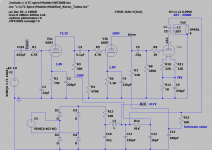
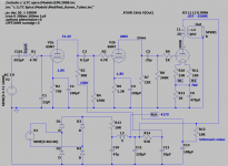
Schematic corrected for 300B at U1. I was originally using a 2A3 spice model as I did not have one for the 300B. Sorry for the confusion.
I have a Hammond 270FX on the shelf. it is specified as 550Vac at 115Vac in. With my line voltage of 130vac that puts me at 621Vac vs the specified 640Vac. Close enough to play with, it measures 661Vac no load.
I have a 200ma Choke on hand. It will have a slightly higher DCR compared to 250ma choke, but should also suffice.
6A3sUMMER - I stated I would change the bias resistor and transformers if I switched tubes.
The voltages on the schematic are from the ebay listing and presume the 300B.
Schematic corrected for 300B at U1. I was originally using a 2A3 spice model as I did not have one for the 300B. Sorry for the confusion.
Attachments
Last edited:
TheGimp,
Please understand. I did not mean to be critical.
In fact, I am always glad when a schematic is posted, even if it is not 100% correct.
There are Newbies that will see that schematic, and build it exactly as posted.
But there is hope for them . . .
With a schematic posted, all of us can discuss any hints, kinks, or problems and their solutions.
There are many schematics posted on this forum, and unfortunately some are not
woking as posted.
I was merely trying to teach the un-knowing about some fundamental principles.
You could print out a .PDF file, and use a little white-out, and make corrections (or use a red pen), then scan the corrected schematic and get a .PDF file to post.
We might have fewer frustrated builders.
Your schematic, Post # 8 has the 1k grid stopper Before C1, the 22pf to ground. Perhaps that is intended to be a low pass RF filter.
But if it is intended to be a grid stopper, the 1k should be after the 22pf (or use two 1k resistors, one before and one after C1).
Most 6SN7 do not need a grid stopper, but some without grid stoppers do oscillate in similar cascade stages.
Last edited:
Good day 6A3sUMMER,
No offense taken.
I have input the schematic into LTSpice from the schematic in the ebay link in post 1 as I use LTSpice for schematic documentation as well as simulations.
I did not copy the schematic from ebay, to avoid copyright infringement but provided a link for others to see it.
I can attach the .ASC file if people want it.
The series resistor and 22pf cap to ground are in the original schematic so it is drawn as such.
Thank you for pointing out the difference between LPF (Low Pass Filter), noise suppression cap, and Grid-Stop topology.
Transformers for 300B
300W transformer Output: 320V--0--320V, 0-5V*3, 0--6V For 300B tube amplifier | eBay
300W transformer Output: 320V--0--320V, 0-5V*3, 0--6V For 300B tube amplifier | eBay
Hammond 270FX: 550vac at 115 - you may get 580-595vac at 130v
I have 620vac at 110v outlet. Then increase to 115v, it reaches 630vac
With tube rectifier, you would lose another 30-50v?
Btw, if you can get B+ at 380+, I thin it's would be fine.
I don't know the correct parts for the PCB but you can see there is no 20w resisters even the complete assembled PCB, there is no big resistors at 300B filament.
To me, I would use the PCB and mod like J.C. Morrison300B single-ended (SE) tube amplifier. Otherwise, don't know if there is any hum problem. If you decide to use as it, make sure to solder the parts with space for easy desolder later.
300B Filament: 5v
2A3 Filament: 2.5v
Looking at the WE300B datasheet under 350V plate voltage and a 3K primary the recommended current and bias are 60mA and -74V.
My choke has 56 Ohms of resistance and my output transformer has 286 Ohms for a total of 342 Ohms. At 60mA the drop is 20.5V.
The Hammond transformer has a resistance of 50 Ohms, So I can figure on 150mA current dropping the open circuit voltage by 7.5V.
Starting at boilerplate spec for the transformer I see:
550/2 = 275
275 Sqrt 2 *130/115 = 439.6V Peak output corrected for line voltage.
5% core loss in the transformer puts it at 439.6 * 0.95 = 417.6V.
417.6V - transformer Resistive loss is 410V
Rectifier loss is say 30V so now we have 380V at the 10R resistor and choke which drop another (66*.06) 4V for 376V (does the choke drop more than the DC loss? I think so, so this is optimistic.
OPT drop is 17V so we are down to 359V at best, probably more like 340V.
-74V bias would require the bias resistor to change to 74/.06 = 1233 Ohms. two 5W 2400R resistors in parallel would be close.
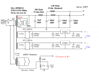
I will use separate transformers for the 300B filaments so the Hammond will not be fully loaded. It will supply the 5U4 and 6SN7s. If necessary, I have an additional 5V transformer I can use for the 5u4 to reduce loading of the Hammond. This should help with voltage sag.
Once I have it built and can make proper measurements with the Hammond, I can decide on a proper power transformer if the Hammond is too low.
My choke has 56 Ohms of resistance and my output transformer has 286 Ohms for a total of 342 Ohms. At 60mA the drop is 20.5V.
The Hammond transformer has a resistance of 50 Ohms, So I can figure on 150mA current dropping the open circuit voltage by 7.5V.
Starting at boilerplate spec for the transformer I see:
550/2 = 275
275 Sqrt 2 *130/115 = 439.6V Peak output corrected for line voltage.
5% core loss in the transformer puts it at 439.6 * 0.95 = 417.6V.
417.6V - transformer Resistive loss is 410V
Rectifier loss is say 30V so now we have 380V at the 10R resistor and choke which drop another (66*.06) 4V for 376V (does the choke drop more than the DC loss? I think so, so this is optimistic.
OPT drop is 17V so we are down to 359V at best, probably more like 340V.
-74V bias would require the bias resistor to change to 74/.06 = 1233 Ohms. two 5W 2400R resistors in parallel would be close.
I will use separate transformers for the 300B filaments so the Hammond will not be fully loaded. It will supply the 5U4 and 6SN7s. If necessary, I have an additional 5V transformer I can use for the 5u4 to reduce loading of the Hammond. This should help with voltage sag.
Once I have it built and can make proper measurements with the Hammond, I can decide on a proper power transformer if the Hammond is too low.
Last edited:
Alashikata, After looking at the picture of the assembled board again, I think they actually use four resistors for the cathode bias resistor. They have have what appears to be two 5W 2.2K resistors and two 1 W or 2W 15 Ohm resistors in a network to get 1115 Ohms. This still puts the bias point at 70mA, which I consider too high for good tube life.
2 5w in parallel would give you 10w, maybe it's not enough, not sure if I am correct.
I have seen most running between 400-420v but saw few running at 380v to extend the tubes life.
The PT may be hot to run at 130v. Mine at 110v running at 120v is hot while 115v is warm around 90F.
Watch out for 450v Caps. It will pop if it goes over.
I have seen most running between 400-420v but saw few running at 380v to extend the tubes life.
The PT may be hot to run at 130v. Mine at 110v running at 120v is hot while 115v is warm around 90F.
Watch out for 450v Caps. It will pop if it goes over.
Mine is running at 430V at the plate, 70V on the cathode with an 880ohm resistor @ 80ma using a 375-0-375 trafco through a 5AR4. If the trafco is wound for 110V you can lower it with a bucking transformer, but I would go with one wound for the voltage you plan to use. I did use 500V caps in the PS to be safe.
[T]he symbol for the second tube is not a 6SN7. I suspect this is a mistake as the tube sockets are two 4-pin, three octal.
Yeah. That's indeed odd. Last I checked a 6SN7 contained two triodes, not a triode and a tetrode.
") The third octal tube is marked 5U4G on the board and the text says "board prevails", so that's not the mysterious driver tube.
The third octal tube is marked 5U4G on the board and the text says "board prevails", so that's not the mysterious driver tube.There's no bias adjustment on the 300B. Not that I can tell anyway. It looks like the part of the schematic that's smeared out is a humdinger pot, not a bias adjustment.
The 16 W must be Chinese watt or measured at 200 % THD. Two channels of 8 W each on a good day, maybe. Given the relatively low bias of the 300B, I doubt you'll get more than 5 W out of it (3-5 % THD).
That said, the 6SN7 can be a nice driver tube for the 300B. If you don't mind a little sand in the glass, it would be worthwhile to consider adding something like Tubelab's PowerDrive: Power Drive | Tubelab to drive the 300B and lower/eliminate the blocking distortion.
Tom
BTW: Toroidy in Poland makes good transformers. I just ordered two custom wound ones - one 200 VA and the other 300 VA - potted, "audio grade" (i.e. with GOSS band and electrostatic shield). Total with FedEx shipping came to 160 EUR! They make high-voltage transformers and OPTs as well.
toroidy.pl
Tom
toroidy.pl
Tom
An Edcor XPWR134, using the 5V for the 5AR4, the two 6.3V to power DC through 5V regulators to the 300B heaters and a separate Hammond 6.3V center tap 1.2a transformer for the two 6SN7 elevated to 35V. I'm running the JC Morrison design that direct couples the two 6SN7 triodes and has one cathode at 1.4V and the other at 75V. I'm also running a split rail setup with 2 chokes after the first LC network. If you try this, make sure you use solid tantalum caps on the 5V regulators.
Attachments
- Home
- Amplifiers
- Tubes / Valves
- eBay 300B PC board kit