.png")


I make errors in breadboarding all the time, plus breadboard connections are not very reliable...
But when I replace both jfets with those that measured 12mA ldss the circuit works. That is, I am able to adjust voltages across R3 and R4.yes, exactly
as is , that circuit can be, both mentally and functionally, cut in upper half and lower half, and they're totally independent
View attachment 1184308 View attachment 1184309
7.8mA would not work.
Yes ground connection for both 10R, yellow jumper on breadboard.
I can't tell anything more than said in #2 and #3
make two separate circs per #3, then try
anyway, why bother with protoboard - go and build amp in proper way
if you're using JFets confirmed by simple matching jig, they're good for amp
upper row figures are for Idss
make two separate circs per #3, then try
anyway, why bother with protoboard - go and build amp in proper way
if you're using JFets confirmed by simple matching jig, they're good for amp
upper row figures are for Idss
Attachments
Yes ground connection for both 10R, yellow jumper on breadboard.
Trust but verify.
Measure the DC resistance directly from the grounded end of each 10R to the power supply ground terminal.
Is it zero ohms?
Some breadboards have breaks in their rail systems, usually in the middle.
Built F5 few years ago using this guide. Thanks to 6L6.anyway, why bother with protoboard - go and build amp in proper way
I used the board by designed by Cviller.
Recently while testing a preamp with F5, left channel was damaged.
So ordered jFet from Diyaudio store. I replaced the jFets, transistors and Mosfets
The problem now is that I can only bias R11 up to only 0.020V.
R12 can bias up to 0.6V easily.
Having spent many hours reading this thread, I also increased the resistors R3 and R4 to 4.7K
but still no changes, cannot bias R11 to 0.6V.
Voltages across R3 and R4 are about 3.6V.
Now at a lost of what to do next.
When constructing, everything works the first time I power up. Joy.
Please help. Thanks
Already posted in F5 build guide.
Tried on pcb board without success.
That is why I breadboard the portion, to find out why P channel jfet not conducting.
Can get my F5 to work with 12mA jfets, but I will face high dc offset problems because
they are not very closely matched
R1 0.2V R2 0.00VAnd what voltage do you see across the 10R resistors R1 and R2?
With limited knowledge in electronics, I think current must flow from V+ to grd then to V-
for R3 and R4 to have voltages. P channel Jfet not pulling?
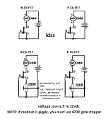
Yes, gates connected to each other only. If you grd the gate, then signal will be gone.the gates of the jfets are connected to each other (via white wire) and nothing else? If so, try grounding that and see what happens
Good point. So for jfets to work there must be ground reference? Maybe that is my my mistake. Will connect gates to ground by 100K resistor and see how.lwithout a ground reference for the gates, the circuit cannot possibly work.
Good point.
you said that you recreated circuit exactly
and then it shows you didn't
up from post #2 that was only possible explanation
So sorry.you said that you recreated circuit exactly
and then it shows you didn't
But with other jfets, both conduct.
Let me try tomorrow and see how.

Yes great.
With the 100K added both jfets conduct now.
My understanding is that jfets are class A device they can conduct without any biasing.
Also my other jfets can conduct without the 100K.
My next step is to install the jfets onto my F5 board and hope that channel can work.
Thanks to all

With the 100K added both jfets conduct now.
My understanding is that jfets are class A device they can conduct without any biasing.
Also my other jfets can conduct without the 100K.
My next step is to install the jfets onto my F5 board and hope that channel can work.
Thanks to all
- Home
- Amplifiers
- Pass Labs
- Only One Matched Jfets Conducts When Connected in Complementary