diy 03 ways, hifi, close speakers

hi guys , im looking for , models brands constructions , hifi woofer , from 10'' TO 15'', low fs , for diy , close speakers , hifi quality sound
-max , rms power , could be 150 W ,- fs could be as low as possible , -4 to 8 ohms impedance , -qts for close charging case , may 0.6
thanks for any help suggestions , brands , good quality produce
sorry about my english not famous
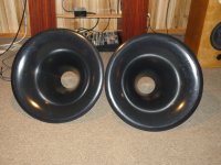
adding this woofer to existing , cabasse O2ways , antigua 220 model , rebuilding the speakers , from 02 ways , to 03 ways
may be changing or adding the crossover surely

thanks

PAM8403 stacking channels option

Hi,

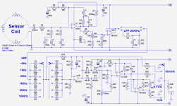
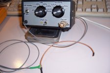
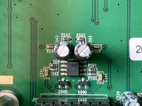
I purchased a small board with the PAM8403 chip. Each channel can do approx. 24 dB gain. I'm working on a simple project using a probe (coil) for interference pickup that I want to make audible (headphones).
I may need more gain than 24 dB and I don't need stereo output. I'm wondering if I can route the output of the first channel to the input of the second channel.

Both outputs seem to be isolated from the ground (measuring > 1MOhm). Is there a way to stack both amplifying sections to get a single channel with up to 48 dB gain?

Regards, Gerrit

pam8403.png

A small hobbyist's component sorting

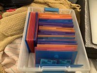
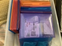
I've looked for various component sorting ideas. I've seen a youtube video of a binder that's normally used for trading cards, with pockets, but I don't like the idea of getting them in and out. If storage is really unavailable, you could do it. I liked the idea of coin pocket holders but still wanted something larger.

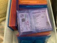
So I found these on amazon (referral link, this one is not) and they work a treat for me at least. They're 5.5 x 7.5 polypropylene envelopes, have a velcro fastener, and are more than enough rigid/stiff to be able to file them. I'm sure there others on amazon or aliexpress.

They have clear ones as well, though I don't mind the colors, that gave me some grouping ability. I tend to leave the components in their original parts bags from Digikey, Newark, Mouser, etc.. But I do highlight the values with a big marker and also mark (and update) quantities on the bags label. Or insert a small piece of paper/index card.
They can expand a bit to hold larger capacitors up to a reasonable size. I was worried they might be flimsy and tear easily at the seams but they were not. Anyways, they work really well for me at home home where space is a consideration. Couldn't do the parts bin even if I wanted to.

Attachments

  • component sortingA.jpg
    component sortingA.jpg
    82.6 KB · Views: 169
  • component sortingB.jpg
    component sortingB.jpg
    72.7 KB · Views: 162
  • component sortingC.jpg
    component sortingC.jpg
    86.7 KB · Views: 167

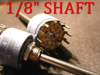
1/8" SHAFT ELMA SWITCHES

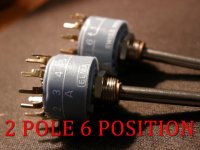
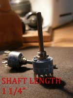
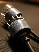
These are for sale since I already have enough of them to use. $30 each. 6 Position, 2 pole. 1/8" shaft with a length of 1 1/4". Of course, you can easily cut the shaft to desired length.
FWIW, the switches are actually grey blue color. For some reason my camera doesn't see it that way.

Attachments

  • P7010001.JPG
    P7010001.JPG
    223.4 KB · Views: 81
  • P7010002.JPG
    P7010002.JPG
    254 KB · Views: 82
  • P7010003.JPG
    P7010003.JPG
    230.1 KB · Views: 82
  • P7010004.JPG
    P7010004.JPG
    303.4 KB · Views: 95

Juma's Easy-Peasy Capacitance Multiplier

I have built many amps and have been working on improving my power supply ripple with the usual CRC or CRCLC circuits. My best effort was actually an Abletec SMPS followed by a CRC where I got 1mV ripple under quisescent bias current. With linear toroidal transformers, I could never get below maybe 5mV and that was with a lot of effort. However, in class A, start pulling a couple of amps and that rises to 20mV sometimes 100mV depending on your trafo and CRC filter setup.

Novi amp sa 2SK2013/2SJ313 - Solid State - diyAudio.rs

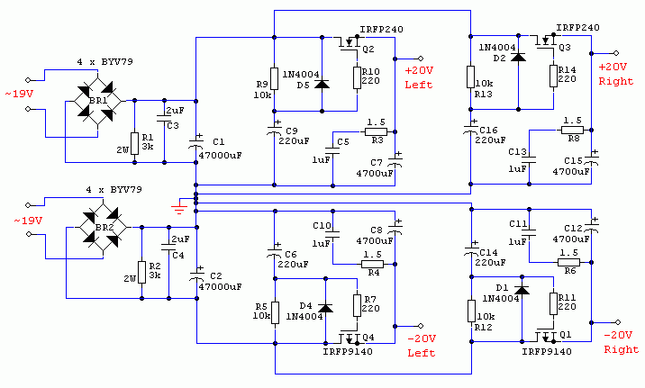
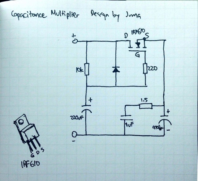
Juma's cap multiplier:

585920d1481786375-jumas-easy-peasy-capacitance-multiplier-juma-cx-schematic.png


Here is nice schematic of the basic core cap Mx for a single rail use by Jwksana:
36990363054_f4dbe6e8e2_z.jpg


I recently built a small class A designed by Juma based on the Pass F5 but using the little 2SK2013/2SJ313 MOSFETs in parallel.

F5 with 2SK2013/2SJ313

The amp works well and sounds very nice. It draws about 1.5amps continuously and I am feeding it with my usual class A power supply: a 400VA 18VAC Antek with a 33mF/0.12R/33mF CRC. I was measuring 20mV ripple per rail and audible hum was coming through when no music was playing.

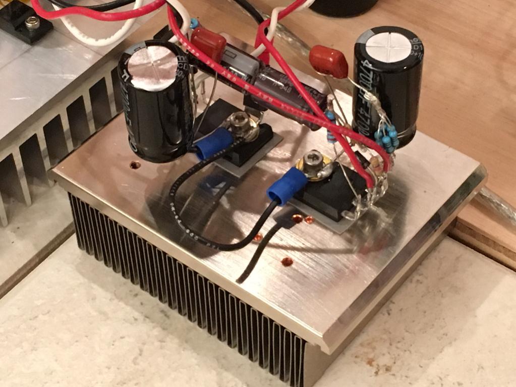
Juma's plans for the little F5 also included a simple capacitance multiplier circuit. It was so simple I had to try it. I have tried others in the past but they were always more complex and typically used BJT's and Darlingtons that I did not have on hand. This one however uses a single IRFP240/9240 per rail, a few resistors and easy to find caps, and a diode. It was so simple I could P2P on the legs of the MOSFET sticking up in the air:

574338d1476275384-very-simple-quasi-complimentary-mosfet-amplifier-f5-j131-k2013-cap-multiplier-closeup.jpg


I powered it up, now fed from my usual CRC that had 20mV ripple under load. There is a 2v voltage drop so you will lose some headroom. However, if you plan ahead, just get a slightly higher voltage secondary rating transformer. Then I hooked it up to the amp and adjusted bias current to usual 1.5amps and now measured the ripple...

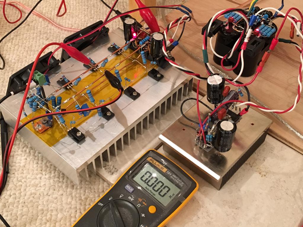
Cap multiplier under test with F5 amp and 1.5amps flowing:

574333d1476267068-f5-2sk2013-2sj313-f5-j313-k2013-capacitance-multiplier-works.jpg


I was floored to see the Fluke AC volts drop to 0.000V AC (across +/- rails at 40v total). Sometimes flickered to 1mV then back to zero again (Fluke 101 has 1% accuracy of measured value + 3, the number added to the least significant digit, data valid over 40Hz to 500Hz range). I would love to have an o-scope to see what it really is doing - but there was a significant improvement in the sound quality. The hum was gone. I will try in my class AB amps next but thought folks might like to try this. It is dead simple and so easy. Anyhow, I think I will be making many more of these in the future and a little PCB would be handy. Just wanted folks to know about what a great circuit this is and to give it a thumbs up! Thanks to Juma for designing it.

If you have any experience with cap multipliers, please share. I have seen the ESP one and the one by Keantoken. This one with a single MOSFET is the easiest one I have seen though.

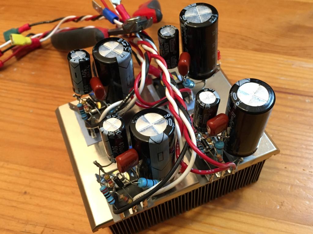
Edit Nov 13, 2016: stereo cap multiplier on one heatsink.

579772d1479032560-jumas-easy-peasy-capacitance-multiplier-juma-cap-mult-closeup-02.jpg


Here is a really nice one by Olafk:

582178d1480173535-jumas-easy-peasy-capacitance-multiplier-psu_juma_ii_02.jpg


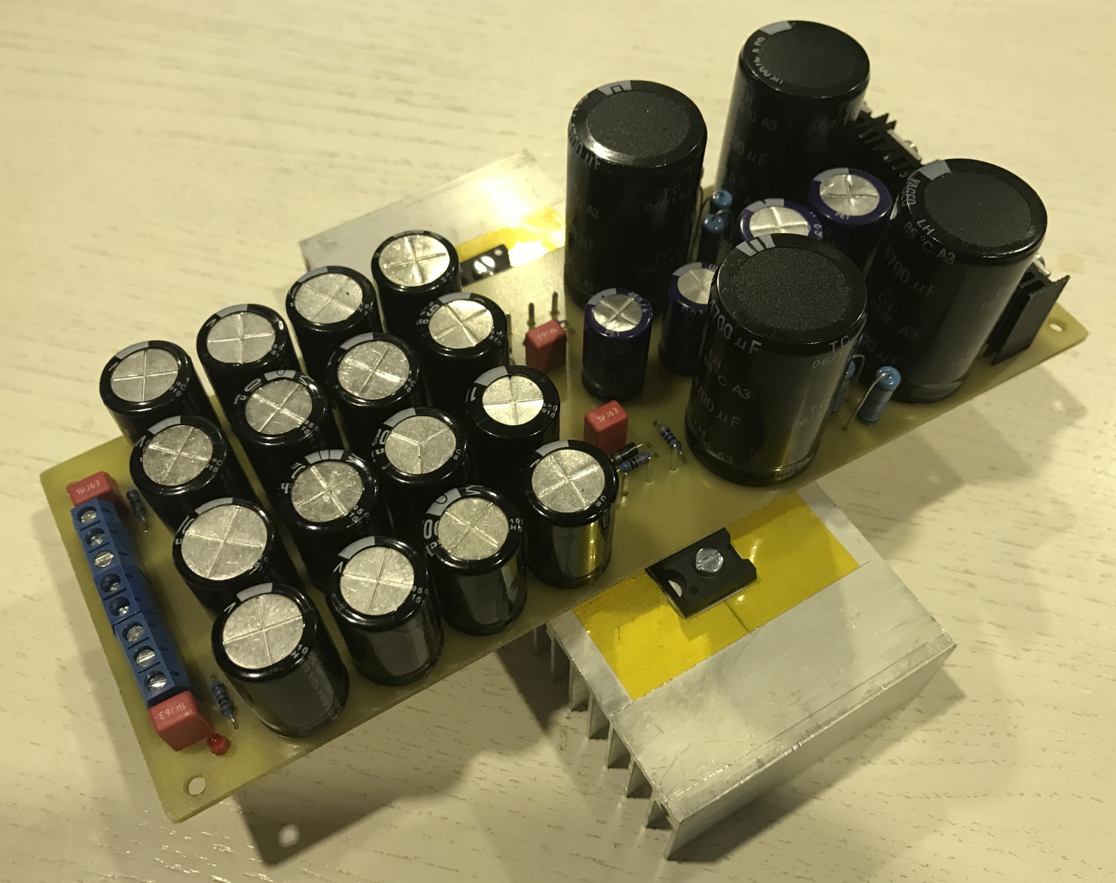
Nice 4 cap Mx on 100mm square PCB by Prasi:
640121d1507959350-jumas-easy-peasy-capacitance-multiplier-juma-cm-png


Gerbers on post 245

Here is another nice one by Prasi for use with external bridge block:
640344d1508086056-jumas-easy-peasy-capacitance-multiplier-juma-cm-external-diode-bridge-png


Small SMT/TO-220 Cap Mx (Dual rail) by Prasi:

714135d1541569887-jumas-easy-peasy-capacitance-multiplier-smd-lay-r1-png


720209d1544046993-jumas-easy-peasy-capacitance-multiplier-smt-cap-mx-build-03-jpg


Works very well.
  • Like
Reactions: Haze Head

Box size with high pass?

I am designing myself a center channel and had a question on box volume. This will be used with the high pass from my reciever set at 80htz. Does it matter what size I choose if all the F3's for the recommend box sizes are below 80htz anyway? Any negatives of building it to the biggest size/ lowest F3? I do prefer the larger size visually. The woofers will be 2 Silver Flutes 8" 4 ohm crossed over at about 250htz or so.

Full bridge rectifier with AC provided by one signal generator

Hi all
A member of my family is doing an experiment about full bridge rectifiers, and I think they are running into some trouble.

They have a signal generator making I believe 10v ptp AC being fed into the AC inputs of the full bridge rectifier (the negative half of the AC wave apparently being connected to signal generator ground), and the DC output being observed on an onscilliscope.

They were running into trouble where the negative half wave was not showing (googling and thinking about this, it's almost certainly due to shared grounds shorting the diodes that would deal with the negative part of the AC wave).

They can now see the "effect" of rectification using some built-in math operation on the scope.

This all seems weirdly wrong to me.

Surely:
1. There is no true AC current as the "bottom" diodes dealing with the negative wa e are only affixed to 0v ground
2. You can't have this circuit working without a transformer (or without 180 degree out of phase dual ac?)


A capacitor was placed (I presume in parallel to output of the bridge) and this appears to have skewed the 2 AC voltage traces on the scope in a strange "camel hump" way. Just seems the circuit I messed up, but I have no circuit diagram (and may not be able to get one).

Any thoughts please?

My only 2 times i have managed to get a full bridge working was via mains 240v AC and transformer (one of which I use daily in my lm3886 DIY build), so I'm a bit unsure if a bridge rectifier can be used without a transformer.

Shorting or non-shorting rotary switch

I am looking for a 2 pole, 12 position switch. I will be using it to switch between two 6 channel devices an AVR and a multichannel dac. So it will be between the dac or AVR and the Amps. Amps will be solid state. Working on a 5 channel Modulus 86 amp. The rotary switches come in two varieties either shorting or non-shorting. Shorting would be a “make before you break” scenario and the non-shorting would be a “break before you make” scenario. So which would be best for my situation? Not planning to switch the ground wires, just the signal wires.

Mark Johnson / Gtose Cap Multiplier

This is a capacitance multiplier designed by Mark Johnson and Gtose. It was first discussed on the Juma’s Easy Peasy Capacitance Multiplier thread. I have created a dedicated thread for it here to reduce confusion as folks have been posting questions about it on the other thread.

A big thanks to @Mark Johnson , @gtose , and @prasi for making this available to the DIY community.

The layout was done by Prasi and details and Gerbers here:
https://www.diyaudio.com/forums/pow...peasy-capacitance-multiplier-post5510507.html

The BOM is here:
https://www.diyaudio.com/forums/pow...peasy-capacitance-multiplier-post6161883.html

Schematic:
cap-mx-gtose-mjohnson_sch_r1-png.1086778


Layout:
IMG_5534.jpeg


Assembled PCBA example of later variant with active bridge by @passive420:
IMG_5535.jpeg


If @prasi can please insert all of his associated designs in this thread that would be great.

Please continue technical discussions here.
  • Like
Reactions: Uunderhill

For Sale USG Muse Preamplifier PCBs and Parts

Hello all,

I have a complete set of new PCBs for this UGS pre. I started to assemble the two shunt regulator boards, but due to some inaccurate silk screen labeling, I blew a couple of the SMDs on one board and was never able to get it to work. I have all the parts still unassembled for the boards, except for the one shunt regulator PCB. That will require some rework. I decided not to continue with the project, and it's been boxed up on the shelf ever since.

I have roughly ~$1000USD invested in this project, that will never likely get finish, so that's why it's for sale. I'm asking $750, plus Priority Mail shipping to the USA only, or reasonable offer.

Please PM me if your interested and I will provide pictures and detail.

Rick
  • Like
Reactions: angchuck

Are there any equivalents for the 2SJ56 and 2SK176, even in a different case?

I have a pile of amplifiers that use the 2SJ56 and 2SK176 TO3 outputs. I personally don’t know if there is anything wrong with any of them, but after opening one of the amps it seems that those are the only parts that might be tricky to replace. Is there a mosfet in to TO3P package and any other package that might work if I’m needed to replace some? I really hope I don’t have a huge stack of paper weights. They are Hafler Pro5000 amplifiers for those that want to know.

Dan

CJ MV55 questions and help.!

Hi there,

I have a MV-55 that I would love some help with; first thing is how can I lower the plate voltage so I can safely run Tung Sol 7581A’s ideally I would like to install a switch that would toggle between the two voltages, any suggestions on how to do this would be greatly appreciated…. Secondly would there be any other modifications required for the bias circuit if the above is doable?

GNFB, I’m struggling to find any information about the circuit and topology, can anyone tell me what level of NFB (if any) the amp has? I’ve obtained a schematic however it seems hand drawn and barely readable..!!

Output seems to be set at 4ohm, there are 2 conductors each (hot and cold) form the opt to binding post and one additional ground wire from the star point on the PCB to the cold BP terminal, also one conductor from the hot BP terminal to the PCB close to the front most bias pots..?? I would like to switch between 4 & 8 ohm if that’s possible with a modification?

Any help in understanding how this amplifier works would be appreciated.

Cheers.!

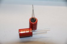
For Sale Rubycon Black Gate N Capacitor Non-Polar 100uF / 16V High Quality Electrolytic

New NOS Rubycon Black Gate N bipolar electrolytic capacitors 100uF / 16V high quality bipolar (non-polar) for signal coupling use. Sold as a pair of two (2). No other Black Gate values are available. No trades or offers please. USA shipping only. $90 plus First Class mail cost; postal insurance is optional. Please pm.

Attachments

  • IMG_4529.JPG
    IMG_4529.JPG
    164.5 KB · Views: 187

A slightly unusual Rogowski sensor

Hi there,

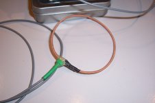
This Rogowski sensor is perfectly ordinary, except for one detail: the sensor coil is wound on the inner conductor of a RG316 coaxial cable.

This type of SHF cable has its inner conductor made of steel, because mechanical resistance is more important than ohmic resistance.

This means that the coil is no longer air-cored, as for a regular Rogowski: the core presents some magnetic permeability. In this case, it is low, because steel has poor magnetic properties, and occupies only a fraction of the core area: the equivalent apparent relative permeability here is ~3.

Why would anyone compromise the main virtue of Rogowski coil, linearity, by adding an imperfect, non-linear core?

Rogowski's are great, but they have a very low output, which is furthermore affected by a 6dB/octave slope, meaning their low-frequency output becomes quickly drowned in noise after the integrating conditioner.

Increasing the permeability improves matters, here by ~10dB: this doesn't look much, but it is far from negligible.
Of course, it also degrades the linearity, and adds a supplementary frequency-dependence: beyond ~20KHz, the steel begins to lose its properties, because of the eddy-currents and the skin effect in the silver plating. This requires additional equalization, but it's no big deal, and for a wide frequency range, equalization is required anyway.
The linearity aspect would become a problem at very high currents only: because the apparent permeability is so low, other effects are "diluted".
I estimated that non-linearities would become an issue for currents of the order of ~1kA.
This could be a problem for me, as I intend to reach peak currents of 1.5kA, but because it will be for a few µs only, it should not be a problem: the magnetic field will not have enough time to penetrate the steel core, and the coil will behave mostly like an air-core one

Attachments

  • Rogo0.png
    Rogo0.png
    68.5 KB · Views: 546
  • Rogo1.jpg
    Rogo1.jpg
    458.5 KB · Views: 513
  • Rogo2.jpg
    Rogo2.jpg
    248.6 KB · Views: 459
  • Rogo3.jpg
    Rogo3.jpg
    521.4 KB · Views: 460
  • Rogo4.jpg
    Rogo4.jpg
    507 KB · Views: 421
  • Rogo5.jpg
    Rogo5.jpg
    525.2 KB · Views: 311
  • Rogo6.jpg
    Rogo6.jpg
    216.5 KB · Views: 370
  • Like
Reactions: Bigun

Conrad Johnson MV50 adjustment?

Just bought a 2nd hand CJ MV50 power amp. I'm surprised by the bias setting of the EL34 output tubes. Because of the 220V to 230V switch during the last 10 years or so, the tube has more than 500V on the plate while the optimal idle current has around 60mA on the meter. That means using the tubes on the edge and implying a short tube life (1000-1500 hours I guess).

So I'm not feeling relaxed about that. The bias can be adjusted by individual trimmers using the famous red led of CJ. Of course I can neglect the LED and just turn to a current of around 45 mA. The problem then is that the negative voltage supply (that gives the bias) end at around -47V which is not enough for all tubes to do the setting. So I have to mod the bias circuit.

Then the problem is: I can't use the visual inspection of the LED's anymore. To re-use that I have to mod the bias circuit yet once more.

Still another option is to bring down the input voltage of the high tension. I can put 47ohm/5Watt resistors in each AC line to lower the DC to around 470V or so (just guessing, total current for all tubes will be around 250 mA). These will become hot, being just a waste of power. But, heh, you have to bring in an offer to save some tube life.

Then again: I don't know how this all will change the sound of the (now very good sounding) MV50.

The last option maybe is using a more robust tube like the 6550 of some KTxx. This I don't like because of the nice character of the EL34 (not forgetting its lower price and fine availability) and then once again I have to change the bias circuit too.

So: I'm not sure what to do. What would you do? Any advice is welcome. Maybe some MV50/52/55 owners out there.

speaker protection relay - do I need diodes across the coil?

as above. I bought a ready-made PCB with all the parts installed and noticed there's no diode across the relay. should I put one? if yes, would a normal 4007 work?

Thank you.
EDIT: there are 2 relays (1 each for both channels)and using a meter, it seems 2 ends of the relay coil are connected to each other. (not sure if this matters but I thought it might be important)

New FDNR topology? Spot the flaw in its behaviour

I was trying out various gyrator topologies, emulated and for real and stumbled across one I don't think I've seen before:
FDNR_variant.png

It looks like a NIC stacked on top of a NIC, but note the opamp input polarities are inverted from the normal. (The choice of opamp for emulation is arbitrary by the way, I used a NE5532 for the physical realization)

This sort of makes sense as this guarantees high frequency feedback is negative and thus stability. It does emulate and work for real. Changing the capacitors for resistors will destabilize this topology so its only suitable for a FDNR, not a grounded inductor.

But there's another catch.

Although its basically stable it can misbehave, and does so in real life - thought I'd leave this for people to muse over and figure it out.

[I should add that this is not intended to be voltage driven, the real life circuit has a source with an impedance of several kohms]
  • Like
Reactions: Elvee

Are my 2SJ56 and 2SK176 mosfets healthy?

I posted a thread a bit ago, asking about replacements for these outputs. I was given a stack of amplifiers that use these outputs. They stopped working, and the person to own them took them to a repair shop and the repair shop refuse to work on them since they couldn’t get parts for them. So he gave them to me. I thought for sure that it would have all shorted outputs, then I would at least have big transformers, and heatsinks if I parted them out. Well, I pulled all 12 mosfets from the first amp and not one was shorted, but they did measure differently on my Peak Atlas DCA75. Some measured as Enchantment mosfets and some as depletion mosfets, yet the specs the meter was giving me was very similar. There was no rhyme or reason as to where the depletion mosfets were. Here is an example, I pulled the 3 2SJ56 from one’s channel and here is how they measured.

IMG_7009.jpeg


The two with the E above them measure at Enchantment and the one with the D above it, well you know. You can see that the measurements the meter gave me are all right in line with the others. Is that just an artifact of the mosfet interacting with the meter? Are they perfectly fine to use?

Thank you,
Dan

For Sale NOS 6P14P-ER Vacuum Tubes

Hi,

I have for sale NOS 6P14P-ER Vacuum Tubes.

Highest grade of 6P14P "ER" version, long life / high reliability.
Reflector Saratov factory, made in 198x.
Some tubes have silver getter, some black-silver, which is completely normal.
Close-up photo of the tubes enclosed so you can see that they are 100% new and not used.

14.95 Euro / pc
Shipping flat rate from EU zone to EU zone only, by post with tracking number. For example, 5 pcs - 10 Euro, 10 pcs - 15 Euro.
Due to the age of item(s) sold as is, no warranty or return.

Photo 23-06-27 14-05-52 7599.jpg
Photo 23-06-27 14-07-10 7600.jpg

Any very good sounding tube headphone amp ideas?

Dear all, I'd like to build my very first tube headphone amp.
Any ideas, a simple schematics maybe ? I'm not an electrician but I can solder and had some little projects already, all with success.

My headphone's parameters:
Max. power rating: 0.05W (50mW)
Max. voltage: 1.2Vrms (3.3Vpp)
Max. current: 43mA
Max. S.P.L.: 113dB
Impedance: 28 Ω
Efficiency: 96 dB/1mW (111dB/1V)

In the future I'd like to be able to drive some more serious headphones with it too, like Sennheiser's HD800S, which seems to be a very different animal (300 Ohms if I'm correct).

I prefer JJ tubes, we have easy access to them in Europe, but actually any brand might be okay as well.

Many many thanks :wave:

2 X 18 B&C 18SW115 Cabinet

Hi dear members. Someone can please help me finding or designing a cabinet for 2 B&C 18SW115? loud outdoor techno, edm, trance and psy trance is the main goal, but i have a problem.. A really big problem. max large 100cm (39,37 inches) not a single cm more or it wil not enter the trunk of my car. I like a lot the style of the EV MTL1 but is too large.. please help me

For Sale CS8412 To CS8414 Upgrade Module

New Crystal CS8412 to CS8414 digital receiver upgrade module for 96kHz/24bit operation. Local power supply bypass capacitors.
This adapter replaces CS8412 digital input receiver with the newer 96kHz compatible CS8414. $60 each shipped. PayPal only. 2 are available.

Sold "as-is" and no warranty is expressed or implied. No returns or refunds. Sells and ships to USA residents only.

Attachments

  • IMG_4659.JPG
    IMG_4659.JPG
    265.9 KB · Views: 88
  • IMG_4663.JPG
    IMG_4663.JPG
    230.5 KB · Views: 99

connecting SME 3009 S2 (ground)

Hi friends
I am redoing my father's TD-125 with SME 3009 S2 imp, and renew the wiring to the pre-amp.
when I opened the connector, I saw that he connected the arm's ground to one channel's ground, thus avoiding a separate gnd-wire...
That sent me into research-modus, and now I am confused.
On one side, I think it is better to go after the books and have the tonearm-/chassis-gnd separated from signal-gnd, on the other hand someone was saying something like "the ground-wires' capacitance adds up... here: https://www.diyaudio.com/community/...ld-style-cable-connector.278825/#post-4438868

What do I do with that? (I'm actually tempted to believe the shield's capacitance does not interfere with the signal's)
So it is still better to keep gnd separated, yes?

Thank you so much!

Attachments

  • 30469336-B9B4-4FDD-B368-7D3B864C1695_1_201_a.jpeg
    30469336-B9B4-4FDD-B368-7D3B864C1695_1_201_a.jpeg
    435.8 KB · Views: 174
  • F1B28EB1-5532-435C-AAA2-CD22418872A2_1_201_a.jpeg
    F1B28EB1-5532-435C-AAA2-CD22418872A2_1_201_a.jpeg
    376 KB · Views: 135
  • 8D19F140-6DC5-46BB-8AB2-31E0F959F859_1_201_a.jpeg
    8D19F140-6DC5-46BB-8AB2-31E0F959F859_1_201_a.jpeg
    531.4 KB · Views: 223

expert advice on reducing port chuffing on store bought powered subwoofer?

So I was given this little jamo sub210 8" ported sub that I want to sell locally to make a few bucks. It functions fine except it has a LOT of port noise. I temporarily stuffed the port just to verify all the noise I was hearing was from the port, and it was. Driver and amp seem totally fine. Port noise is so bad, you basically have to turn it down to the point of barely being audible/useful, so it's not a matter of me playing it too loud (volume was at 12 o'clock/half). I'm also aware of the factors that cause chuffing (too fast air speed due to port size or overdriving). The port is about 2" wide, about 4" long, and has flared ends. I'm not terribly concerned with slightly altering the tuning. I think a buyer would notice the loud chuffing before they'd notice a slight loss of output or tuning change. My options are (A) just plug the port. (B) Completely stuff the sub with polyfill ($5/bag) and leaving port open. (C) Completely stuff with polyfill and plug port. (D) Remove port, make the hole bigger by about and inch or two and install a larger port depending on how much room I have on the baffle. If I increase the port width, how do I determine the larger port's length? Btw, while the port was temporarily stuffed, I was playing bass sweeps and after a while I noticed one spot on the plate amp was very warm. Any chance of damaging the amp in case it relies on the air movement from the port for cooling? With the port open and playing bass sweeps, the air coming out of the port could be felt a couple feet away. Again, this was a normal listening levels (volume was at about 1/2 (half). Thx.

Denon PMA 1510ae Gain 45.5dB

Hi.

I'm looking to lower the gain of my Denon integrated. As it has to much gain for modern sources (input sensitivity is 125mV) and Gain in Amp stage is a whopping 45,5dB.

The easy way would be to add some external attuniator s i guess, but that feels like a bad solution.

I would like to reduce the stepup in the voltage amp stage but sadly my skills in electronics are not up to par with the task.

So is there any experts here that can advise on any adjustments so that the input sensitivity would be about 300-500mV,and gain 39-34dB

Attachments

Matching BG RD75 planars with Magneplanar ribbon tweeters

Hi all,
I have a pair of BG RD75 planars.
They are crossed over with some Marchand XM46 line level passive crossovers driven by Conrad Johnson Premier 8XS' monoblocks. I have been using 3 pairs of Aurum Cantus G2Si ribbon tweeters but plan on replacing these with some 60 inch Magneplanar ribbon tweeters for a true matching line source. I imagine that these are a natural pairing. I was hoping that someone might have some suggestions re; crossover frequencies/slopes and designs.
Thanks in advance.
Cheers, Peter

Will this tweeter work well in one of these circuits?

My friend owns a the pair of speakers featured on Paul Carmody’s website, the older, original Carrera using the 15w Revelator and Hiquphon OWIII (has the gold dome). It uses the original OWIII that was replaced with the OW3 when they needed to change the dope used on the dome.
IMG_6723.jpeg


It uses this crossover.
IMG_6841.png

IMG_6842.png


Since the OWIII went away Paul swapped over to the OW1 using this crossover.

IMG_6839.png

IMG_6840.png


Of course the woofer circuit had no changes. My friend said this is hands down one of his most favorite pair, he listens to them daily. I have a large collection of raw drivers and I’m wanting to build something with what I have on hand and of course I have interest in building this-ish.

I have the correct woofer, but the tweeter I have is the OW2, falls right between the two lol. After doing some reading I found out that the OW2 has less mass and is considered a faster tweeter, better with the upper end while not being as clean with lower frequencies. My friend and I talked a we agreed that of the two crossover that the one designed for the OWIII would be the one to start with. Being that the OWIII and OW2 have the same 90db sensitivity while the OW1 is 87db. Also the frequency response for the OW2 ans 3 look nearly identical.

Here are the specs, I’m basically just wanting to know if this idea is worth the effort of moving forward and of the two crossovers which would you use.
IMG_6960.jpeg


I would love to get started on this build, but only if it makes sense and will sound good. I wish I had one of the drivers that Paul designed with, but spending any extra money right now isn’t going to happen.

Dan

Peppy Player config screen reboot not working

I am using Marc version on a 3B+ with RPi 7" screen.

From the browser config screen, clicking Reboot caused the music to stop playing, the screen goes blank (backlight is on) but the screen never comes back. During that time opening an SSH into the player still works so Peppy is running. Then, from SSH do a sudo reboot, it actually does a reboot. Or, doing a "sudo shutdown now", the backlight goes off and I hear an audible click. There is no click when Peppy is shut down from the LCD screen power button and the backlight stays on.

"Sense" circuit for MCU ADC (STM32 / ESP32 / Arduino etc...)

Hi.

I'am trying to make a voltage sense circuit for a microprocessor 🙂

I have the ESP32 developmentboard set up to sense a voltage level on it's ADC.
For a start I build an active rectifier with an LM833 opamp.
With this active rectifier + smooting capacitor I can measure fairly good and stable levels within 0.2v ---> 3v (RMS sine)
Next step is to calibrate the ADC so values from 0 ---> 3.3v can be measured. https://github.com/e-tinkers/esp32-adc-calibrate
So far that is good.

But I would also like to have the possibility to measure the output from differential output.

So I could use the circuit below to feed my ESP32 (Diff. to SE ---> Active rectifier ---> ESP32)
I was wondering if I can feed the diff. to SE circuit with an SE input also (+IN to Vin1 and -IN/Vin2 to GND) this way I can use it for both diff. and SE measurements.

I can ofcause just try it out, but I would like to understand it before I do.

One last thing, I don't need crazy exact / precise values!

Jesper.

Diff_to_SE.PNG

Design Considerations concerning Electrolytic Capacitors in an Outdoor Tube Amp Power Supply before and behind Choke

Several years ago on the power amplifier model "Compact 100" from VTL - go to
https://www.diyaudio.com/community/threads/vtl-compact100-monoblock-blows-fuse.170592/
was made various modifications.

The modifications mainly consisted of optimizing the ground routing (GND management) for hum reducing, converting from ultralinear (penthode operation) to triode operation, as well as swapping out the mains transformer, rectifier and installing high-quality electrolytic capacitors to replace the cheap old ones.
Due the now present outdoor power supply the problem of lack of space is eliminated - thus a small outline for parts isn't longer necessary.

Shortly I try an additional step to further increase the sound quality; the introducing of an inductor.
I choose the Hammond EDB196M4, 5mH or 20mH choke - go to
https://www.hammfg.com/files/parts/pdf/196M4.pdf
for connecting between rectifier for anode voltage (~400VDC) and the already present electrolytics - at whole 1,5mF (1.500µF).

Now the question rises up, what value of capacitor I need between rectifier and choke (I use in the moment only 150uF and thus achieve a further improvement in sound quality).

The fundamental question must actually be - which rules must be observed with regard to the value of the capacitors before and behind of the choke.

Are there papers resp. app-notes concerning this question ?

Thanks for an advice.

P.S.: The whole idle (quiescent) current of each VTL mono power amp is 150mA and the current while listening at normal level therefore is the same value (CCS-character resp. class-A character) - 35mA for each EL34 and 10mA at whole for both the input and phase splitter-tube.

This threads don't provide the wanted information:
https://www.diyaudio.com/community/threads/choke-where-to-begin.232116/
https://www.diyaudio.com/community/threads/power-transformer-and-choke-effect-on-sound.376885/
https://www.diyaudio.com/community/threads/electronic-choke-for-valve-amplifiers.173280/
https://www.diyaudio.com/community/threads/tube-power-supply-and-chokes.344853/
https://www.diyaudio.com/community/...mplifiers-which-rules-for-calculating.199645/
https://www.diyaudio.com/community/...ke-for-power-amp-psu-inductive-filter.382441/
https://www.diyaudio.com/community/threads/best-placement-for-a-choke-vht-tube-amp.256167/
https://www.diyaudio.com/community/threads/choke-inputs.254978/
https://www.lundahltransformers.com...MI5KXQyb3M_wIVhgiLCh26CAWCEAMYASAAEgKySPD_BwE

Glue tweeter to aluminum with jb weld or screw - aluminum panel is old tweeter one - matches other drivers brackets

Hello,

Should i use JB weld to bind the tweeter to the old tweeter aluminum panel or use screws? the drill bit i have is too large, so would have to get a set to match and screws to fit, as the dayton screw cutout is only for a certain size of screw.

images of the messy project. I am doing this to keep with the coral speakers aluminum surrounds.

Thank you Sam
P1480842.JPG


P1480843.JPG

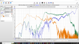
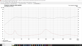
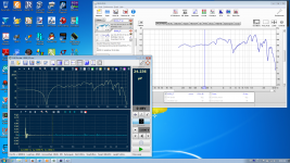
Speakers measurements with Room EQ Wizard

Hi,

Today I have used for the first time Room EQ Wizard with my mic behringer ecm8000 to measure my old DIY speakers.

All drivers was measured at only 2 cm from mic.

After these measure I got confirmation that the crossover need an upgrade.

First is clear that the woofer is not 90 dB like the midrange and the tweeter (as usually happens).

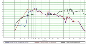
There is a strange unstability at 170/200 Hz that happen only if the woofer is inside the box, but is not clear the cause.

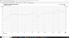
The measurements are very different from the simulation (2010) like I expeced but I don't sure how I can interpret these differences.

I have simulated a possible crossover update (2023) with more flat frequency response.

Any suggests ??

Thank you !!

Attachments

  • All (2cm distance).png
    All (2cm distance).png
    160.5 KB · Views: 232
  • All (Similated freqiency response).png
    All (Similated freqiency response).png
    55.2 KB · Views: 184
  • Woofer SPH250KE (SPL SL-5878P).jpg
    Woofer SPH250KE (SPL SL-5878P).jpg
    148.3 KB · Views: 120
  • 2023_Woofer_measure_from_dibirama.png
    2023_Woofer_measure_from_dibirama.png
    57.8 KB · Views: 171

Anyone have the Zaph 12 speaker project(seas L15+27TFFC) archived?

I bought an L15 driver a long time ago and kept it.
I've been wanting to make a speaker using this lately, but I can't find data.
I would be very grateful if someone could send me a copy of Zaph's page.
What I particularly want to know is about L15.
Infinite baffle response, box response, T/S parameters, and how many liters he used and what Hz he tuned.
If doesn't exist copied page, can anyone tell me just only these?
9635osj@gmail.com

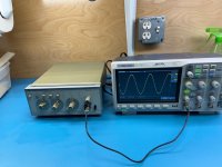
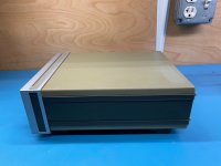
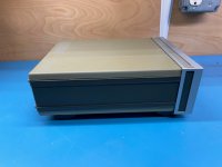
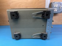
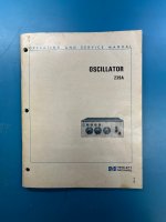
For Sale HP 239A Oscillator

Working unit in very good cosmetic condition. The top has some discolorations. The front panel plastic switches have no cracks. The front panel lettering shows no deterioration. The dial lettering shows some wear but still very readable.

Factory service/operation manual included.

The function switches could use a little cleaning, but the unit settles on the desired frequency and level.

This oscillator does not come up for sale very often.

$350 plus shipping. How about $250 plus shipping.

hp239a.jpghp239b.jpghp239d.jpghp239e.jpghp239f.jpghp239g.jpghp239h.jpg

Attachments

  • hp239c.jpg
    hp239c.jpg
    413.9 KB · Views: 208

JAB5 output bridge

Hi!
Recently I bought JAB5 amp from Wondom which has 4x100W @ 6ohm outputs. Problem is I was so sure that it operated at 4 ohm load I bought all of my speaker parts to be at that impedance level. Speaker RMS is 40W and i highly doubt if I would ever push it through.

I have read somewhere online that if those 4 outs are bridged to 2x200W the output impedance tolerance would also half. Is that true?
What could I expect connecting 4 ohm speakers to 6 ohm out frequency graph wise? (I know amp could burn)
Can such setup be working without fire in my house at a fracture of max output power so that it wouldn't overheat?

Reason I decided to go with this amp is for if I would want to upgrade my system in the future with more speakers. Or should I just go with 2x50W @ 4 ohm amp from Wondom?

EDIT: I found an alternative amp from Dayton Audio which looks the same (KABD-4100). The spec sheet is also the same but it says that outputs are stable down to 4 ohms. Anyone tried that?

For Sale Ian Canada OPA861 Balanced I/V Hat

Bought this a couple of weeks ago and should have read the manual in more detail before doing so. It's intended for balanced use only really and I'm S/E throughout. The manual states S/E output for function testing only. Doh. Tested, and all working fine, but I am inevitably not getting the most out of it. Needs a +-5v PSU. Need to free up funds for other stuff, so, on it goes.

Bought direct from Ian at 129 USD, which is £103, Audiophonics have them at 185 Euro which is £158!

Selling for £90 inc uk postage. Will post overseas at cost.

Can sort out photos if needed, details below

https://github.com/iancanada/DocumentDownload/blob/master/RPiDacHAT/IVboards/OPA861IV/OPA861IV.pdf

https://www.audiophonics.fr/en/dac-...-balanced-zero-feedback-iv-stage-p-17013.html

Pass full range driver network-adapt for Lii Audio Fast-15?

Decware makes a product to smooth out the response of the Lii Audio Fast-15.

https://www.decwareproducts.com//product-page/fast-15-network

It is, of course, optimized for the low power tube amps that company specializes in. I just came across this article by Nelson Pass in which he details a more complicated network intended for use with solid state current source amplifiers

https://www.firstwatt.com/pdf/art_cs_amps.pdf

In the article he tests a range of smaller wide range drivers made by Lowther, Fostex, and others and defines values for each component that optimize the high end response to minimize the nasties. Tests were with the drivers in a sealed box. I'm curious to try this network with a pair of Lii Audio Fast-15 drivers I'm building tall open baffles for (they will be used with a distributed bass array). Has anybody tried adapting this network to any of the newer, larger full range speakers from either Lii company or other Chinese manufacturers? How would values change in an open baffle setup? Disclaimer-I understand the basics of crossovers but not the details. I was trying to avoid anything between the speakers and the amp! However, it seems it might be needed for these drivers.

Classical musics that are peacefull to listen to? looking for

Hi,

I am not unexperienced with classical music but it is not my main daily fooding. (10 % according the day)

I am looking for a daily one hour or so daily listening for a 86 yo sweet ma bornt before WWII , some classical musics which are :

  • no agressive (Wagner when exploding, just for illustration)
  • imo : not explosive orchestra with bass
  • not too much religious corpus (requiem and so on)
  • something on the melody side whatever big orchestra or small ensembles

Mainly sweet classical without dark and sad sides (Requiems and Messiah not welcomes for illustration)

Not limited but I already thougth about- according my limited knowledge- to:

Fauré (listening to 13 Nocturnes var 6 , rigth now)
Some italians and french operas (I am ok here, not needing too much advices)
De Bussy
Hayden
Chopin
Handel (water music style)
Some Mozart (huge corpus, so needing advices from more experienced enthusiasts than I)
Satie and Ravel (limited corpus for what I am looking for)
Haendel
Ravel

Whatever: but on the neutral, calm, and smile side of classical music. Exhausthing music forbiden.

Many thanks for your experience 🙂

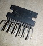
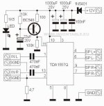
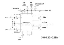
Pin 12 of TDA 1557Q

Hi, i want to build a small chipamp for my shop & i like to try Tda1557Q but i'm confused about pin 12 (Input reference voltage?). Also should i connect pin 11 directly to +VCC or using resistance between is advisable? Value? There are many schematic on the net but i'm not sure which one to follow for best result. As power supply i have a 12V 3A transformer.

20230519_115941-1.jpgFB_IMG_1684604978026.jpgscale_1200.jpeg

Muzishare X7 vs R8

This is a final overview video of the muzishare X7 vs the R8 and some tube rolling advice. After some extensive listening tests, ended up with a set of KT88-Z black coated tubes, a gold lion 12AX7 and the gold pin version of the EH 12AU7 with the supplied Sovtek rectifier. This setup in the X7 sounds really nice and clean. The X7 also clearly outperforms the R8 with another carefully selected set of tubes and extensive mods.

Login to view embedded media

Multi Function Test Device?

I've been using a Digilent AD2 PC test device for a few years. I'm thinking it might be time to purchase some actual test equipment. Other than my dmm, I mostly use only a scope, wave generator, dummy load, and voltage divider. The AD2 provides the scope and wave generator and I built a 4/8 ohm dummy load and a 2/1 voltage divider. When I test something I've usually got a ton of connecting cables and scads of adapters for for joining different types of connectors. My work space usually look like a Rube Goldberg creation; and I spend a lot of time chasing down illogical readings caused by loose connections, etc. Anyway, a device that combined some or all of these functions could be appealing. If it was available used, that would add to the appeal.

Any thoughts would be appreciated.

6T10 Mighty Midget - resistor selection

I'm just starting a build of Pete Millett's Mighty Midget compactron 6T10 amplifier and note that the Bill of Materials has a mix of metal film, carbon film and carbon comp resistors. I imagine Pete (being the wizard he is) has a good rationale for selecting the various types of resistors for this circuit.

Which resistors are critical for the signal path of the amplifier? There is a good sale on at Parts Connexion at the moment - some of the boutique resistors are over the top in terms or pricing but if anyone can recommed a reliable brand for these types it would be appreciated!

Attachments

I have replaced the Eton 5-312 with the Purifi PTT5.25-inch woofer-mid!

Here's the previous YouTube of my 2-way prototype with the Eton 5-312 "Running Wild."

Login to view embedded media
and now here's the Purifi PTT5.25X08-NFA-01 as a "Drop-In Replacement."

Login to view embedded media
I am thrilled!

Yeah, there's work to be done on integrating the ribbon, but I also think I am going to move up and try a different ribbon anyway.

amb,

john
  • Like
Reactions: lrisbo

Streamer, server, and confusion

Greetings all,

I had recently started to transfer my (mostly CD based music), onto a general purpose file server. The file server OS is a "real" UNIX - OmniOS, FreeBSD, if it matters. I then connect to the remote server via NFS, SMB/CIFS, depending on the OS of the local computer I am using, and play the file with a music player on the local computer. So the content of the file is transfered over TCP/IP from the remote server to the local computer.

Several of the topics in this section discuss different implementations of streamers. So, I was trying to understand what the term means, but as usually the Internet iis less than helpful, in fact rather contradictory. To wit:

The difference between a Music Server and a Music Streamer is a Music Server has digital outputs a Music Streamer has analog outputs
So, a Streamer is a device that purely fetches the digital information over the network, and hands that to a DAC, while a Music Server is a more complex device, able to run music cataloguing software such as Roon, to organize your music library.
and so on.

So, I was wondering if someone could explain the difference and if not clear from the difference a user case for each.

Kindest regards,

M

Stereo signal distribution

Hello Guys,

I wanted to drive 6 speakers from 3 stereo audio amplifiers. Audio input will have to be same for all 3 amplifiers. Audio source I'm having is my mobile phone. The doubt I'm having is, can I distribute audio signal to all 3 amplifiers from my mobile's 3.5mm jack? If I do so, will it lead to clipping of audio signal or should I use any other circuit in between my 3.5mm audio output and amplifier's input? Please share your valuable suggestions.

Help: Converting Interface to Analogue Preamp

Hello, first-timer here so not sure if I’ve posted this is the right thread.

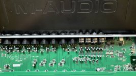
I have an audio interface — M-Audio Fast Track Ultra 8r — which has become obsolete in terms of manufacturer support and signal chain compatibility. The device does not have daisy chaining capacity, meaning I cannot integrate it into my signal chain as a digital device; hence, I wish to convert it to a standalone analogue preamp in order to plug it into an ADC to expand my I/O and integrate the device into my signal chain.

The idea is to somehow rewire (or de-wire) the internals to bypass the AD/DA converters between mic input to line output, making the signal flow completely analogue and unadulterated, to then be converted with an ADC.

This will likely be an audacious DIY job by myself — unless someone in the UK is willing to take on this task for me — as I have no electrical hands-on experience, so may botch things and lose a device. Thus, I need the DIY community’s help and guidance through the process.

This is the information I have gathered so far, though I am uncertain if it is entirely correct:

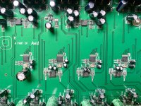
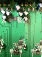
Receiving/Input amps: JRC4580 dual op amps
Gain op amps: THAT 1510
Individual TL072C JFET amp
I do not know if there are buffer amps nor how to discern one. Kindly see the attached images and let me know if you can spot any.
Output op amps are also JRC4580
ADC are AK5386 rated up to 226/192kHz 24-Bit. There are 4, so I assume each one is for each stereo input pair.
DAC are AK4384 rated up to 192kHz 24-Bit. Also 4 of these.

Images of the PCB board are attached for anyone to offer guidance.

Any assistance and guidance would be greatly appreciated.

Attachments

  • IMG_4418.jpeg
    IMG_4418.jpeg
    446.7 KB · Views: 111
  • IMG_4404.jpeg
    IMG_4404.jpeg
    569.3 KB · Views: 94
  • IMG_4429.jpeg
    IMG_4429.jpeg
    489.5 KB · Views: 87
  • IMG_4398.jpeg
    IMG_4398.jpeg
    508.1 KB · Views: 88
  • IMG_4407.jpeg
    IMG_4407.jpeg
    535.3 KB · Views: 100
  • IMG_4406.jpeg
    IMG_4406.jpeg
    629.8 KB · Views: 96

For Sale Nutube preamp with DIY BIAMP 6-24 CROSSOVER

NOTE FOR MODS - Could you please change the title of this thread to :

Nutube preamp with DIY LXMini crossover

#########################################################################################################

This is a B1 with Korg Nutube with a DACT CT2 stepped attenuator and the DIY LXmini crossover all in one case with 2 meanwell smps power supplies. I did not build the unit but I've been using it without fault for a while now. I'm looking to get £250 which is what I paid for it and still think it's a great deal.

The crossover point is currently set at around 350hz. It says on the diy audio store website that the RC values can be changed for different crossover frequencies and slopes. -> https://diyaudiostore.com/products/analog-crossover-network

Based in Bristol, UK.

Preferred UK sale.

Attachments

  • 20230421_113631.jpg
    20230421_113631.jpg
    590.3 KB · Views: 329
  • 20230421_113659(1).jpg
    20230421_113659(1).jpg
    533.3 KB · Views: 322

Ti dome HF breakup notch filter sims

For those interested in removing the HF breakup peak on a 25 - 28mm Ti dome tweeter, here are a few calculations I've made to accomplish this. You can get very close to the actual shape of the peak with a very simple filter.

I've tried this notch filter with my Audax TW025A28 Ti domes and it works very well. Looking at the 16 dB+ peak at 25.5k, its not a bad idea to try taming this dog whistle of a peak. You can vary the peak amplitude by changing the parallel resistor. In my case, 33R is the value that worked best. I used my Earthworks measurement mic to verify this which is flat to 30k.

A trained ear can definitely hear a difference with recordings that have extension past 20k, mainly classical and acoustic music. It passes the "triangle test" and also playing cymbals.

Attachments

  • 20230628_160741.jpg
    20230628_160741.jpg
    97.7 KB · Views: 145
  • 20230628_160639.jpg
    20230628_160639.jpg
    305.9 KB · Views: 148

A Treasure Trove of DIY Projects

A DIY bonanza. I have built projects my entire long life, just retired with plans that include major de-cluttering.
I’m offering a bargain for the right person. I’ve cleaned offer my workbench and dug deep into my cabinet of projects that were waiting for me to complete.

Now I’m offering them to you for $650 plus shipping for these boxed up items…most in original packaging from the DIY Audio Store, others opened so that I might check values of components, yes, many upgraded components and hook up wires included in this offer.

  1. two black faced ACA Amp Camp Amps (brand new v1.6) and their completion packages (i.e. chassis, back plates, etc.), at least two "Meanwell" power supplies
  2. One ACA Camp Amp (v1.5 or 1.6) in chassis but not finished wiring
  3. One Korg Nutube B1 preamp ( B1 with Korg B1K Full Kit )
  4. One Starving Student full headphone amp kit with two sets of alternative vacuum tubes
  5. Muffsy Phono Preamp PP-4 with power supply & chassis, etc.
  6. The Muffsy BSTRD - Class A Tube Preamp PCBs
  7. New in box MarkAudio Tozzi One Full Range Speaker Kit -- Pair with black case

I want you to be completely satisfied with your purchase. I have carefully packed up (often double boxed) this gear to be shipped to you. I can be available by telephone, email, or Personal Message to answer any questions that you may have.

Respectfully, Kevin Balog oh, for shipping estimation this gear current resides in my home in a Northern Suburb of Indianapolis. I would ship from either Fishers or Carmel Indiana. Hope this helps.

Kenwood eXelon KAC-X301T instantly turns on....

This amp turns on instantly when you apply 12v to b+ and ground with nothing else.

I cannot find any damaged transistors at all.

Pin voltages on the NEC494 appear instantly the main power and ground are applied with no REM.
1: -
2: 5.11v instantly
3: -
4: 0.22v instantly
5: 3.0v triangle wave floating at 0.3v above ground
6: 3.81v instantly
7: -
8: 12.49v instantly
9: switching
10: switching
11: 12 49v
12: 12.49v
13: 5.11v
14: 5.11
15: 5.11
16: -

Pin 4 being dead time control, shouldn't it start out high and drop low instead of instantly going 0.22v?

Should i use this transformer for LM1875 with 4 ohm loads ?

Hi everyone, i hope you are having a nice day.
So after building my first lm1875 amplifier that was single supply i was very happy with the sound quality, But it does have some issues mainly due to the power supply.
So now i want to build my first proper amplifier in a proper chassis.
Basically i have a toroidal transformer that was free from some junk electronics. It has 2x16v 5 amp windings and some low current windings that i could use for a protection circuit.
After rectification with one 6800uf capacitor per rail i get 24vdc per rail and with around 1.5 amp load it drops to around 21vdc per rail
That seems ideal for lm1875, But i want to use 4 ohm load so i am slightly worried.
Although the amplifier is going to be used with markaudio chn-50 speakers that are rated at 7w so its probably never gonna reach the current limit.
I am planning on using this chassis or something similar:
https://www.audiophonics.fr/en/alum...iy-box-100-aluminium-260x166x70mm-p-9500.html

And these boards with genuine parts
https://www.ebay.com/itm/20W-HIFI-M...p4429486.m46890.l6249&mkrid=711-127632-2357-0

So do my plans seem ok or should i consider something else ?
If anyone has any better amplifier design for these voltages and loads pleas tell me, But it has to be a design that has pcb designs available.

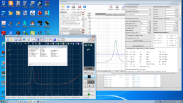
CLIO Pocket

My CLIO pocket has been working in my lab for over two weeks. It is a nice speaker measurement tool. I used the bigger brother CLIO-FW before. Its firewire interface was not stable. Pocket uses USB and does not need an external DC supply. I have not encountered any connection problem. I also like its software supporting Windows and OSX!

The software does not have those advanced features of CLIO-11. But it is sufficient for my driver/enclosure measurement. One drawback is that it can not open MLS, SIN files saved by CLIO-11. On the other hand, I can export measured data to text file (impedance, frequency data) and wav file (time data). These export files can be processed by other tools like REW. I can use REW to calculate TS parameter to compare with CLIO pocket derived parameters. REW can show us how good the model fits the measured data.

I can also import impulse response (wav file) to REW. The impulse response can then be windowed by different window functions whereas Pocket software has just rectangular or half-hann windows. REW also allows more control on waterfall display. Spectrogram can also be generated.

Attachments

  • pocket.jpg
    pocket.jpg
    667.8 KB · Views: 2,820
  • REW.png
    REW.png
    724.3 KB · Views: 2,702
  • REW TS.png
    REW TS.png
    601.8 KB · Views: 2,601

Removal of non-used tubes in Audio Research SP11

Introduction
I have a Audio Research SP11 (Mk1) tube pre-amp to drive my Threshold SA/1's amps.
I like the combination more than the FET 11 pre-amp from Threshold themselves.

Context
I do have a turntable which I use on and off mostly off...
The Thresholds are single-ended so no need to use a balanced output (SP11 has a non-inverted and inverted stage).

Question
There are six 6JD8/6922 tubes in the SP11 three in the phonostage ((V1, V2 and V3) and three in the line stage (V4, V5 and V6).
V6 is for the inverted signal and cutout when you use the ´Direct' outputconnectors at the back of the main unit.
There are four powersupplies in the separate PS unit that feed the active circuits in the main unit.
1. HV section supplying 300V B+
2. 12V to logic mutingcircuit
3. Filaments 12 Volts (except V2)
4. Filament V2
All of this is much better explained in this discussion: https://soundmovements.co.uk/diyaudio/SP11.html
I wondered if I could just when not using phono or inverted out remove the tubes to perform these duties so V1, V2, V3 and V6?
Less stress on the Powersupply, less heat less AC intake.

Also my toroidal gets pretty hot to the touch but I think that is caused by:
"The high-ish transformer secondary voltage, giving raw 400VDC, will give a good tolerance to mains undervoltage, though the MOSFET voltage rating will have to be 500V or more to ensure it isn't damaged by over-voltage. This MOSFET (Q26, MTM2N45) is mounted on a large heatsink and will get quite warm in use, since it drops eighty volts or so at about 150mA."
For reference the Schematics and some pictures of the actual unit. I already removed that odd 10.000uF JCCon radial left from the upper orange Roederstein 4700uF axial cap.
- PSU
PSU AR SP11.png

- Linestage
Linestage AR SP11.png

- Phonostage
Linestage AR SP11.png

-photos of PSU
20230201_152522.jpg20230201_152528.jpg20230201_152540.jpg


- photo of Main unit
20230201_151311.jpg

Attachments

  • Phonostage AR SP11.png
    Phonostage AR SP11.png
    689 KB · Views: 196

For Sale Fosgate Audionics 4200 Power Amps

Up for grabs here are a rare Fosgate Audionics 4200 amp. Highly acclaimed predecessor to the Harman Kardon Citation 7.1.


2.5kW transformer with 100k mfd of capacitance. Four channels of 200 watts into 4 ohms (125 into 8 ohms.) Or, bridged 600 watts/4 ohms stereo. THD/IMD less than 0.03% at rated output. Four RCA inputs, four sets 5-way binding posts out. 19"Wx8.5"Hx17.5"D. 62 lbs. Input Impedance: 50k ohms. Input sensitivity: 1.0 volt full output. 120/240VAC. THX certified.


Not the prettiest, but sound excellent! $350 plus shipping or pick up. Can be demo'd at local music store.

Attachments

  • 48CDC463-D845-48D3-B25B-570A39C8C112.jpeg
    48CDC463-D845-48D3-B25B-570A39C8C112.jpeg
    439.8 KB · Views: 248
  • 8ED25CB8-D339-44A5-A4AF-95CC4793147B.jpeg
    8ED25CB8-D339-44A5-A4AF-95CC4793147B.jpeg
    439.7 KB · Views: 252
  • A3B7BA67-35E9-4CB5-A01F-F00BB5199472.jpeg
    A3B7BA67-35E9-4CB5-A01F-F00BB5199472.jpeg
    431.9 KB · Views: 233

Fixed Wattage Amplifier with Regenerative Battery Power

It seems as though all amplifiers perform best when they are at driven at near the maximum of their power range. An amp that is 200w at 8ohms for example will likely produce a lowest distortion signal close to that 200w point, beyond which the distortion spikes at 200w.

Is it possible to establish stasis where an amplifier is constantly operating at its near maximum output and lowest distortion point regardless of the input signal and volume? The methodology I would envision is that any excess power that would push the amp to clipping is in a sense "drained." This is obviously inefficient and a waste of electricity. Given this, perhaps battery operation would be an interesting solution, where excess power would be used in a regenerative capacity to charge the battery which powers the amplifier.

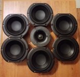
What to do with 12 x Peerless 830870 midbass drivers?

I got ahold of 12 pics of Peerless 830870 midbass drivers and wanted some ideas for a fun project with them.

I bought them based on their very flat and extended FR and other specs.

I was thinking of perhaps a circular array with 6 drivers surrounding a horn loaded tweeter of sorts ie. Morel CAT378

Any ideas or thoughts?

Attachments

  • 20230416_214852.jpg
    20230416_214852.jpg
    271.6 KB · Views: 233
  • 20230416_221011.jpg
    20230416_221011.jpg
    515.4 KB · Views: 219
  • 20230416_220822.jpg
    20230416_220822.jpg
    479.4 KB · Views: 244

Bi-Amp Problems

Hi all, first time posting in here, so i own a set of EV T252+, a BBE Max X2 crossover, a peavey CS1000 amp and a QTX PRO 1000 amp. I wanted to biamp the EV's so i opened up the backs and followed the instructions to set them up for biamping, but somethings just not right, i have a friend who builds PK rigs in the US and i checked all my wiring with him which he said was spot on. So heres what happens, if i have the amp on that powers the highs, and the one that powers the lows off, then fine, i can hear the mids and highs fine, when i do the opposite, the sub/lows sound great... but when i have them both on, the bass essentially dissapears, and i only get mids and highs, and if i turn up the lows it all just distorts rather than the lows getting louder.

Any idea what is going on?

Thanks in advance,

C

Tubelab SSE PCB -- 70% complete w/ Mundorf Mcaps -- 12AT7 tube

Hey everyone.

I bought a Tubelab SSE PCB a while ago and started building it, but some other things got in the way and I never got around to finishing it. I'm now looking to sell it.

The board is about 70% complete, it's just missing a few components. It also comes with a Electro-Harmonix 12AT7 tube. The missing BOM components are included. I just didn't have time to solder them.

The board was 50€ + customs fees. There was an additional 50€ worth of BOM components from Digi-Key. Anddd an additional 55€ for the tube + 2 Mundorf MCAPs. The components were soldered using Mundorf Supreme Silver solder. Approximate cost of the whole endeavour was 150€.

I'm looking to get 80€ + shipping for it through Paypal.

I am based in Belgium, but I can ship anywhere you'd like.

Best to you all,

IMG_1667.jpg
IMG_1668.jpg
IMG_1669.jpg

IMG_1671.jpg

IMG_1672.jpg

Pass Labs INT-250 Modifications

Hi,
I've completed a few modifications to my Pass Labs. INT-250 and thought I would share what's been achieved.

First, the monolithic regulators on the INT_8_MB_R1 Pre-amp board.
These are New Japan Radio Co., Ltd. parts and have lower output noise levels than regulators from other vendors. Ripple rejection is also listed from the vendor datasheets:
U1JRC 7905A-5V100uV60dB
U2JRC 7815A+15V90uV70dB
U3JRC 7915A-15V170uV67dB
U8JRC 7805A+5V45uV78dB

Now things have moved on since the original design with vastly improved discrete alternatives available from SparkoS Labs., Inc.
Parts and specifications listed below:
U1SparkoS Labs. SS79XX 796.8 custom -6.8v-6.8V3.5uV-125dB
U2SparkoS Labs. SS78XX 7815+15V6uV-125dB
U3SparkoS Labs. SS79XX 7915-15V6uV-125dB
U8SparkoS Labs. SS78XX 786.8 custom +6.8v+6.8V3.5uV-125dB

There are some differences in the way the two vendors conduct their measurements. Even taking that into consideration, the discrete parts offer significantly improved performance, also for load regulation.

I won't get into superlatives, but this offers a serious improvement and I'd always felt the INT-250 was capable of yanking a much higher level of performance out of a set of speakers. To me, music is about emotion and you can really feel it.

I've seen comparison elsewhere between high-end integrated (Diablo 300 The Gryphon) and the INT-250 where the defining difference was listed as low/mid bass, dynamics and micro-details.
I'd say these are exactly the areas that improved. It's no small improvement either and I'd recommend anyone that owns one of the Pass integrateds (likely also pre-amp's) and is so inclined to try the modification.

I think the step-up is due to a combination of pure regulator performance and also the increased reservoir from the integrated 10uF tantalum polymer output capacitor.

Note: I've listed the recommended SparkoS regulator parts. You can use (but it's not recommended) the SS7805 as a drop in replacement for the JRC 7805A (Pass use a red LED as a low noise method to increase the regulator output by its forward voltage); however it is not possible to use a SS7905 for the JRC 7905A -5v regulator.
Furthermore, the LED must be removed and the GND connection shorted to ground for the 796.8/786.8 discrete parts, no dramas for an enthusiast.

Some images:
U1 (I also added the heatsink for U1) & U3
U3 SparkoS 79xx N15V_04.jpg


Next, dealing with the rather resonant steel top cover.
This was done with Monacor MDM-830 bituminous felt, it's around 4mm thick and perfect for the job:
Monacor MDM-830 bituminous felt_01.jpg


The other mod is more aesthetic, a bit of cable dressing:
front panel cable support_01.jpg

fabricated from 2mm dry carbon sheet
front panel cable support_04.jpg

  • Poll Poll
Bose SL2 Transmitter Sync cable pin out

What is a pin out for SL2 RCA connecting cable?

  • Audio connector

    Votes: 0 0.0%
  • RCA

    Votes: 0 0.0%

Hello Friends.

I lost a sync cable for the Bose Lifestyle SQL Transmitter wireless module. I enclosed a picture of a cable. It is an expensive to replace and trying to do it myself. I need your help if you could provide a pin out for this cable. Basically a 4 conductor audio jack map to RCA connector. Which conductor connecting to the RCA jack?

Link of a cable selling at Aliexpress

Thank in advance for your help.

International Differences

[Music] Many build systems for stats or authenticity, others, for purpose. It has occurred to me that Europeans have genres that Americans don't have. In Garage and Hardcore the bass is the lead. There was an era where club owners replaced drivers more often than light-bulbs. We are not talking about the odd church-organ note or movie explosion. We are talking about relentless abuse by kick and bass with no time to cool.

If you're from the US and hooked-up, tell me if your preferred genre offers more punishment than this . . .

Login to view embedded media
Projects by fanatics, for fanatics
Get answers and advice for everyone wanting to learn the art of audio.
Join the Community
507,714
Members
7,885,582
Messages

Filter

Forum Statistics

Threads
406,105
Messages
7,885,582
Members
507,714
Latest member
sjun1019