Well the other day my beloved trusty Tektronix 2430A greeted me with a self test fail.
🙁 Of course this always happens in at the most inopportune moment, as usual.
😀
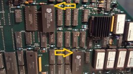
I am sure others have seen this issue before me. I am trying to describe what I did try to get the scope back to working order, perhaps this may help someone who is facing the same issue. As it turns out the very special NVRAM chips have finally lost battery charge and corrupted the cal data checksum. The offending chips are U664 (Cal Data) and U350 (Waveform Data). Both chips in my scope were Dallas DS1235ABW-120 vintage 1990. I would not want to complain as these chips kept data much longer than what they were spec'ed at.
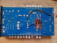
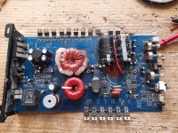
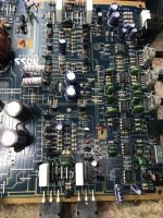
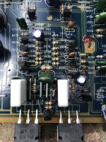
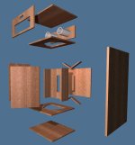
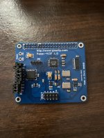
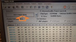
🙂 I found some old new stock on ebay with a fairly 'recent' mfg date and bought some. Despite the corrupted data in these chips, I decided that I may have nothing to loose if I tried to read these chips in a programmer and perhaps pre-load the replacement chips with whatever I can read out of the old ones and perhaps reduce any calibration efforts. As I did not have a programmer, I turned to ebay and bought a cheap one Model TL866CS. I removed the main-board for convenient access as the offending chips were not on sockets and needed to be unsoldered, I installed sockets for the new chips and would recommend that. The old chips still contained some data got loaded into the new chips without problems. Then the pre-loaded chips were installed on the sockets and the main-board was installed and reconnected.
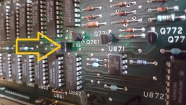
Then as part of the calibration procedure, jumper J156 must be removed to enable extended calibration feature. After successful calibration this jumper should be put back.
I believe I read that it is advisable to operate the scope only with installed case as the air flow is as ist should be, otherwise if the scope is operated without the case in place it may not have sufficient airflow and some chips could die due to overheating.
The calibration is very easy, one needs a decent variable lab power supply that can provide up to 20.0V, A few BNC cables and adapters may come in handy also.
With the enabled calibration features and warmed up scope
Initiate EXT CAL
Run ATTN cal, and follow on scope screen instructions.
Run SELF CAL and turn off scope and turn back on.
Run TRIG cal, and follow on scope screen instructions.
and turn off scope and turn back on.
Run REPET cal.
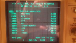
Run SELF DIAG to confirm the errors were cleared and the scope now passes self test.
If needed repeat calibration as per above.
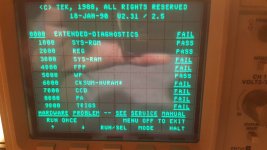
This should clear the following self test errors
3000 SYS RAM
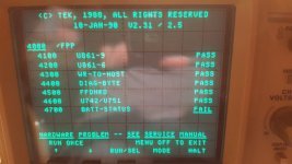
4000 FPP
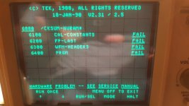
6000 CHECKSUM-NVRAM
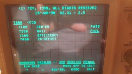
7000 CCD
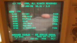
8000 PA
9000 TRIGS
Now, I am a happy camper again
😀😀😀

I like my Tek Scope and hope it will remain in service for a very long time.