In 1980 I built the Maplin lateral mosfet amplifier.
This was based on a Hitachi datasheet lateral mosfet amplifier schematic.
It worked well.
A few years back I decided to see if I could modify it to use irfp240/9240.
So designed a new pcb with new outputs.
I added a dc offset pot, Vbe multipler and decoupling of front end to reduce hum.
Not a bad sounding amplifier.
Last edited:
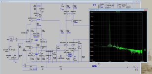
Awful graphical display, but those were the 80's. You were an early adopter of this editor.
I used VAX-VMS-spice in that time and 24pins needle printers for the plots. And a calculator.
I used VAX-VMS-spice in that time and 24pins needle printers for the plots. And a calculator.
Nice, thanks for sharing. I tried to sharpen the diagram... not sure how successful my attempt was...

Dear Nigel, with due respect , your schematic is impossible to read.In 1980 I built the Maplin lateral mosfet amplifier.
This was based on a Hitachi datasheet lateral mosfet amplifier schematic.
It worked well.
A few years back I decided to see if I could modify it to use irfp240/9240.
So designed a new pcb with new outputs.
I added a dc offset pot, Vbe multipler and decoupling of front end to reduce hum.
Not a bad sounding amplifier.
View attachment 1215919
To boot, it only uses a section of available space and seems to be just a screen capture.
Can´t you please "print" the schemtic, to, say, a PDF virtual printer (think CutePDF or similar), cropping useless space away, black lines on white background (hint: like a printout) and since we are at it, using somewhat thicker lines?
It would be WAY more readable.
Saving to .gif or .png would also avoid the .jpg artifacts which have NO place in a Technical drawing, ( .jpg was created for HIGHLY compressed vacation and birthday party snapshots).
Thanks.
Hi Nigel,
Yes, it will work with those different mosfets. However (don't you just hate that?), the newer ones you used have something called "gate charge" characteristics.. They must be driven with a low impedance, higher current driver stage and they still are not great. The lateral mosfets do not have this mechanism, so it's much more than simple biasing.
-Chris

That design is the "olde English" he he (HH audio amps). One of my "5 minute wonders".
(below) is it's simplest form - HH drove lateral mosfets direct with it. I drove a vertical EF with it - perfect.
Hitachi did a little better , this topology in "21'st century form" (below 2) can beat the Wolverine !
You do have to add a few more parts .... but get sub PPM.
OS
(below) is it's simplest form - HH drove lateral mosfets direct with it. I drove a vertical EF with it - perfect.
Hitachi did a little better , this topology in "21'st century form" (below 2) can beat the Wolverine !
You do have to add a few more parts .... but get sub PPM.
OS
Attachments

Yes , laterals have high'ish gate capacitance , but less. HH ran the posted VAS at >10mA with appropriate gate resistances toThe lateral mosfets do not have this mechanism, so it's much more than simple biasing.
"get er done" , Bigger multiple lateral OP stages used a BJT driver pair. Holton "aussie" amps also uses this topology (with drivers)
and lateral (Exicon ECW20N200 with a whopping 900pF gate capacitance.
OS
I don't have the gear to test this IPS. But it has 72db loop gain at 20Khz versus >50db for the Wolverine.Really, beat the Wolverine? I'm impressed.
Notice the input stage is the Wolverine's .... but add that Hitachi balanced VAS - and "magic" happens.
Edit - the gear i have just says 0.
OS
Yes, but they did not suffer from gate charge issues like the IR parts. That was a step response as you increased gate - source voltage.
Beat the Wolverine - is subjective... At this point the distortion is down at the noise floor.
Semi 's will determine what beats what.
Edit , but .... it does clip better (almost self clamping).
OS
Semi 's will determine what beats what.
Edit , but .... it does clip better (almost self clamping).
OS
There have been around 4 generations of vertical mosfets, with the same part numbers, but very different linear behaviour. In general the SOAR has become worse every generation. This means that you need a lot of derating
Derating isn't a bad thing. You don't want things to run too hot. Having a little extra current capacity never hurts either.
Derating is normal practice in the BJT world.
Derating is normal practice in the BJT world.
I tend to use larger a heat sink and a fan.
I quite often use a cheap old pc case and use the mains socket and fan mountings on that.
I had a fan pack up on me once during a gig.
My pint was on top of the case.
It wasn't until I sipped a warm beer I realised the amp was cooking.
I quite often use a cheap old pc case and use the mains socket and fan mountings on that.
I had a fan pack up on me once during a gig.
My pint was on top of the case.
It wasn't until I sipped a warm beer I realised the amp was cooking.
With very high power amplifiers, a fan is common. We're talking 200 watts and up and they have large heat sinks also. There is no excuse for a smaller amp to require a fan. Convection cooling is enough if you have the right heat sink.
I use a Marantz 300DC into a low efficiency speaker, 4 ohm load. I pound it for hours. It gets very warm, but not hot and I do not need a fan. The transformer gets pretty warm then as well. It's outputting more than 200 watt peaks during this.
I use a Marantz 300DC into a low efficiency speaker, 4 ohm load. I pound it for hours. It gets very warm, but not hot and I do not need a fan. The transformer gets pretty warm then as well. It's outputting more than 200 watt peaks during this.
- Home
- Amplifiers
- Solid State
- Visiting an old friend