Philips CD100/101 , Marantz CD63 overheating problem

I had two of those players and they were working fine but this one keeps overheating after an hour or so and the laser power supply goes down. It works fine without bottom cover. Before I start changing Regs and PTC resistor maybe somebody had similar problem with this family of players ?

Attachments

  • CD63_power_supply 001.jpg
    CD63_power_supply 001.jpg
    58.2 KB · Views: 84

For Sale Speaker Sale

Blaupunkt P652c 6 1/2 two way. Pair NIB $50.00

4" Coated Paper Mid/Woffer P/N 55-1200 8 ohm/40W. Used pair $40.00

3" Paper Tweeter Bukooo DO7776/2M24 8 ohm 40W Used pair $20.00

1" Mylar Dome Tweeter P/PN11028-584560 New $25.00

All OBO, Paypal plus shipping.

Attachments

  • Blaupunkt_P652c.jpg
    Blaupunkt_P652c.jpg
    224.4 KB · Views: 601
  • Blaupunkt_P652c2.jpg
    Blaupunkt_P652c2.jpg
    155.2 KB · Views: 597
  • 4inchMID.jpg
    4inchMID.jpg
    165.1 KB · Views: 586
  • 4inchMID2.jpg
    4inchMID2.jpg
    144.6 KB · Views: 577
  • 3inchpaper.jpg
    3inchpaper.jpg
    74.7 KB · Views: 577
  • 3inchpaper2.jpg
    3inchpaper2.jpg
    118.6 KB · Views: 142
  • MylarTW.jpg
    MylarTW.jpg
    146.8 KB · Views: 135
  • MylarTW2.jpg
    MylarTW2.jpg
    119 KB · Views: 131

HK870, 50v DC on speaker terminals

Bought with blown right channel, all 4 outputs blown. Pulled blown outputs, bypassed with 1k resistors to track voltage. Wouldn't leave standby. Replaced some bad components, still standby. One transistor on the driver board and the two caps in the protection circuit, out of protection, 15mv offset on right. 50v on left. Shut it down immediately. Outputs still okay on diode check, I don't have another set, so being very careful.
Where do you start on something that far out of wack? Going to bypass the outputs and start checking the circuit again. Seeking a bit of advice.

Restore and upgrade crossover Rane AC23

HI, I bought an analog electronic crossover, i.e. non-dsp, Rane Ac23.
It has a couple of power caps that are a little swollen, so I wanted to change the 6 power caps there.
The power supply has a voltage multiplier. 10.5+10.5vac enter the crossover (external transformer) which are multiplied by two and then pass through the 7815 and 7915 regulators. The crossover operates at dual voltage +-15vdc.

Do you think I can use Panasonic FC for all 6 capacitors even if in different positions?
I attach the diagram.

I ask because I seem to have read that low ESR capacitors, downstream of the regulators in question, can generate oscillations or, in any case, not be optimal.

Also I wanted to ask why the TL072s are on sockets and the other OPs are not.
I would also like to upgrade the OP, many years have passed since its production and perhaps there is something better.
Does it make sense to just change the TL072s on the sockets? Or would it be necessary to also put sockets on the other dip14s and mount other OPs?

I would also like to eliminate the subsonic and ultrasonic filter.
I attach the diagram.

Thanks for any help.

Attachments

  • ALIMENTAZIONE.jpg
    ALIMENTAZIONE.jpg
    92.4 KB · Views: 252
  • SCHEMATIC 01.pdf
    SCHEMATIC 01.pdf
    978.7 KB · Views: 154
  • SCHEMATIC 02.pdf
    SCHEMATIC 02.pdf
    884.1 KB · Views: 124
  • 20231108_153756.jpg
    20231108_153756.jpg
    535.9 KB · Views: 219
  • 20231108_153811.jpg
    20231108_153811.jpg
    347.1 KB · Views: 218
  • 20231108_153819.jpg
    20231108_153819.jpg
    342.6 KB · Views: 219
  • 20231108_153826.jpg
    20231108_153826.jpg
    374.4 KB · Views: 205
  • 20231108_153842.jpg
    20231108_153842.jpg
    344.5 KB · Views: 334
  • 20231108_153848.jpg
    20231108_153848.jpg
    312.5 KB · Views: 208
  • 20231108_153903.jpg
    20231108_153903.jpg
    335.2 KB · Views: 204

12AT7WA tubes

Hello..
Just stumbled over theese very nice and unused Raytheon tubes.
I have no real interest in tube audio and would like some offers.
Black plates and tripple mica.
Took all careful out to photograph, same batch all

Attachments

  • 20231112_124624.jpg
    20231112_124624.jpg
    290 KB · Views: 86
  • 20231112_124643.jpg
    20231112_124643.jpg
    241.4 KB · Views: 85
  • 20231112_124826.jpg
    20231112_124826.jpg
    385.3 KB · Views: 78
  • 20231112_124854.jpg
    20231112_124854.jpg
    389.6 KB · Views: 74
  • 20231112_131504.jpg
    20231112_131504.jpg
    368.7 KB · Views: 76
  • 20231112_131534.jpg
    20231112_131534.jpg
    366.3 KB · Views: 71

For Sale Electronic Instruments for sale - pickup only (Germany), sorry

A friend of me passed away some time ago and now I help his wife to dissolve his workshop.
She is not able to ship adequately, so pickup in Kerpen/Germany (near Cologne) is possible only.

As far as I know, these devices are all in fully operable condition

Rigol MSO2302A Oscilloscope 2Ch. 300MHz 2GS 350€
Panasonic VP-8193A AM/FM-Signal-Generator 350€
Two older PSUs 10€
Distortion-Meter 20€ reserved
Siemens D2002 Function Generator 20€ reserved
Hameg HM1005 Oscilloscope 2Ch. 100MHz analog 40€


Rigol.jpeg


Panasonic.jpeg


PSU.jpg


THD-Meter.jpg


FunctionGen.jpg


Hameg.jpg

DIY add on Input stage for Class D module

I recently built a class D dual mono amp from (2) Icepower 1200AS mono amps. It's my first experience with class D. I went from an Adcom 5802 to this. They couldn't be further from each other in sound. The Adcom 5802 was all weight and overly fleshed out and a little on the dark side with my 12" + 15" combo and the Icepower is big fast and light. Almost too thin and quick. I was watching Paul McGowan's, from PS audio, recent video on "Stereo vs Mono amps" and he was showing off their input stage (w/ tube) for the exact same module that I have. He said that it "was where the magic happens" with their amp. I want to bring back some of the weight and flesh out the bass a little more than what the 1200AS is doing. I don't want to copy/steal what PS Audio has but is there something along those lines out there? It doesn't really have to have a tube. I'm more interested in sound but a tube is fine too. Thanks

For Sale Audio Note L1 (Clone Board), Fully Constructed

To sell 1 fully constructed board for Audio Note L1 EL84 amplfier

Please have a look at the photos.

Amongst other very good components:
- Nichicon Audio Capacitors, B+ filter
- Elna Silmic II
- Black Gates on the EL84 Cathodes
- Audio Note Tantalum resistors in some specific places
- Audyn Copper Max Signal capacitors
- Mills resitors

Fully working, and tested.

If you want to build a full amplifier, look to my other threads for the power transformer, Lundahl output transformers, EL84 Tubes, ECF80 Tubes.

Price 350€ + Shipping (please consult).

I accept Paypal.

Attachments

  • AN L1 1.jpg
    AN L1 1.jpg
    127.4 KB · Views: 896
  • AN L1 2.jpg
    AN L1 2.jpg
    75.4 KB · Views: 845
  • AN L1 3.jpg
    AN L1 3.jpg
    74.6 KB · Views: 804
  • AN L1 4.jpg
    AN L1 4.jpg
    119.8 KB · Views: 864
  • Like
Reactions: pompiliu

A tweeter choice Yet, advices needed!

Hello,

Any idea guys for a silk tweeter 2000 hz XO ; > to 90dB/2.83V ; as detailled as the metal SB26CDC to challenge it, please ? Budget less than 250 euros/USD max the pair

MTM with 5" hard paper units (NE149W).

I thougth about to the Bliesma T25S or the wave guided Morel CAT378/TW30A11 ? SS 2604/83000 ? small Illuminator twweter cans ? SB26STAC ( a liitle hot maybe in the highs and not liking too much low cut off as many SBACOUSTIC SB26)
Can be horned too but not sure it is worthing with 5" woofers ?!

Coming from daily aluminium tweeter use I am looking for something detailled enough and blending fine with a detailled papaer cone at the level of a Satori paper driver.

I wanted initialy a compression driver for its dynamic behavior but gave up the project for a 3 ways with 2 5" MTM for the medium area.

Thanks for your thoughs.
  • Like
Reactions: motokok

Recreation first analog to digital with 1942 Thyratron tubes

Bonjour, just got a new set of matched 1953 vintage RCA 2050 Thyratron Argon tetrode tubes.

Installed into the SIGSALY Quantizer ADC recreation, now calibrated perfect 6db/step CAL.

From my IEEE Spectrum Feb 2019 article.

Your thoughts appreciated.

Jon

Attachments

  • Quant2c.jpg
    Quant2c.jpg
    326.9 KB · Views: 159
  • Q2quantNOV23.jpg
    Q2quantNOV23.jpg
    173.7 KB · Views: 156

For Sale TAD TD4001 Pr, SEAS L26ROY Pr, Stax L300, Ortofon Cadenza Red, B&C DCM50, Markaudio MAOP 11

Selling the following audio equipment:

-Pair of TAD TD4001 Beryllium Diaphragm Compression Drivers -- Mint: https://www.ebay.com/itm/276137126769
-Stax L300 Earspeakers -- New: https://www.ebay.com/itm/276143706880
-B&C DCM50 -- New: https://www.ebay.com/itm/276130266031
-Pair of Mark Audio MAOP11 Drivers -- Sold
-Pair of Seas L26ROY 10" Subsoofers -- Sold
-Ortofon Cadenza Red -- Sold

FS: Trans-Fi Terminator linear tracking air bearing tone arm

This is a complete package, which includes absolutely everything to operate the tonearm - the complete tonearm itself, the wands to hold cartridges, air pump, smoothing tank, extra tubing, extra wires. You will get 6 wands to mount six different cartridges. You will get extra wire to connect the cartridges to Molex connector. You will get the "VTA on the fly" gauge, if you are really picky about that parameter. You will be amazed how much better it tracks the grooves than most pivoted tonearms, no matter the cost. There will be no inner groove distortion, and no need to futz around with protractors.
The only thing that you will possibly require is the mounting column, depending on the thickness of the platter on your turntable. Any machine shop can make you one, if you need one that's longer that I'm including.
Cartridges and the turntable are not included, they are shown only for reference purposes.
The tonearm is ready to be assembled, provided you will have the proper height mounting column. Don't be freaked out by all the little weights, wires and screws: these are all just extras, that you'll probably never need.
Set-up instructions are very easy for those with modicum of mechanical sense, and are available on the TRANS-FI website.
Trans-Fi Audio - MANUAL

$XXX includes postage in the USA.

SOLD

Attachments

  • IMGG2824.jpg
    IMGG2824.jpg
    587.7 KB · Views: 354
  • IMGG2832.jpg
    IMGG2832.jpg
    551.1 KB · Views: 345
  • IMGG2852.jpg
    IMGG2852.jpg
    1,005.8 KB · Views: 400
  • IMGG2826.jpg
    IMGG2826.jpg
    405.4 KB · Views: 360

Output impedance measurement - without load?

Hey everyone,

I would like to measure Zout of my amp. This requires measuring voltage at the speaker output with and without a load.
Now I've always been told that a working tube amp always needs a load. See my problem (?) here?
Would it be okay to have a dummyload at the output, measure the voltage and then briefly disconnect that dummyload? One second should be enough.
I'm not sure...

DC-DC Converter (Switch or linear) Help (Lowest Noise Possible)

Hey there everyone!

New to electronics in general, but need help with an issue I'm facing for a personal project. Anything that could help would be much appreciated!

I'm trying to design a circuit that boosts DC to DC cleanly in the power section for an audio preamp I'm working on (500 series).

The preamp portion of the circuit is sort of plug and play as I've used it on other designs but the power section is what is hindering me from continuing on!

Now, I'm wanting to start with a +/-16vdc input in the actual real world application. (Variable input of something like 12-24v would be even better here!)

I need the output to be able to achieve a steady 400vdc or as steady as it can be. (Variable output up to 450v, 500v would be awesome too!) (CCM maybe?) (I don't know what I don't know)

The current doesn't matter much to me. Maybe like 5-20ma in the 400v range roughly.

Should I go with a boost converter? Flyback Converter? Do I use a high frequency transformer? Etc.

The only stipulations to my idea are:

not a ton of space to work with (500 series PCB for power and preamp circuits on final design).

I need it to be the cleanest output at 400v as I can get (minimize ripples).

Even if just providing schematics and parts that work on paper I can do all real world testing and man hours myself.

If you could work with me in anyway with a schematic and some parts that could be used for this, it would be so very much appreciated!

I've been all over asking for advice to no avail.

Thank you all, I hope we can all work on this 🙂

DIY Raspberry Pi KIT for Music Server / Streamer / Player / Digiamp (R23-MAX)

* SOLD *

Hi, I'm selling another new Raspberry Pi DIY KIT. The KIT includes all of the necessary parts to build a Raspberry Pi Player / Streamer with built-in linear power supply. You will need some basic soldering skills and it takes at least 2 hours to assemble the parts. There will be an extra 7% for PayPal service charge. Shipping cost will be incurred depending on destinations. (I truly understand the shipping fee would be a bit high, but the case is made of 5mm thick aluminum, it weighs 4.6kg)

Usage of the KIT:
-Digital transport / streamer, supports Spotify, Tidal and Qobuz
-Media server with an internally mounted 2.5" SSD (not included)
-Digital to Analogue Converter with I2S DAC HAT
-CD player / ripper with an external USB CD drive (Volumio premium user only)
-An 25W/ch Class-D amplifier (Need to install an 80VA power transformer)
-Supports mainstream audiophile OS including Moode Audio, Volumio, piCorePlayer and DietPi
-Ropieee is NOT supported

Case:
-Aluminum alloy fabricated with mixed CNC and LASER cut
-All black anodized matte finishing
-7" HDMI QLED touch screen
-Can mount an 2.5" SSD internally
-Opening at the bottom, can change OS with ease
-Dimensions: 250(W) x 230(D) x 150(H)
-Support standard D-type sockets
-RCA jacks included
-Native support for Allo Boss 2 DAC HAT

Power:
-40VA audio grade R-type transformer, 5A output
-Built-in LPS, 1% load regulation, 80dB PSRR (120Hz)
-8x Nichicon FW Series capacitors
-Ultra low ESR, CLC filtering topology, WIMA MKP10 for final decoupling

Price:
HKD2300 (~USD293)

Shipping Cost (for reference only):
US: HKD780
UK: HKD471
Other countries: (Please PM me for more details)

********************************************
Note:
Supports Raspberry Pi 4B ONLY
Touch screen is included
No Raspberry Pi or DAC included
********************************************

YouTube demo:


Login to view embedded media

Work as a digiamp:


Login to view embedded media

BOM:


https://drive.google.com/file/d/1D8ZXTLZsc3j0oJM8sRBXY5xWawEYq5bD/view?usp=sharing

Attachments

  • DSC_5567.JPG
    DSC_5567.JPG
    265.1 KB · Views: 708
  • DSC_5568.JPG
    DSC_5568.JPG
    297.8 KB · Views: 618
  • DSC_5572.JPG
    DSC_5572.JPG
    275.9 KB · Views: 614
  • DSC_5575.JPG
    DSC_5575.JPG
    254.5 KB · Views: 650
  • DSC_5587.JPG
    DSC_5587.JPG
    247.9 KB · Views: 2,282
  • DSC_5588.JPG
    DSC_5588.JPG
    289.6 KB · Views: 867
  • DSC_5593.JPG
    DSC_5593.JPG
    336.6 KB · Views: 850
  • DSC_5594.JPG
    DSC_5594.JPG
    457.1 KB · Views: 814
  • DSC_5600.JPG
    DSC_5600.JPG
    364.1 KB · Views: 712
  • Like
Reactions: Haze Head

Tweaking parameters at driver's out-of-range

Assume we have two speaker series, Mk1 and Mk2. The woofer low-pass filters on these two speakers are identical; the only difference is the presence of a 1 Ohm resistor connected to the 100uF capacitor. The circuits are depicted below. Mk1 components are labeled "1" in their names, as are Mk2 components.

lowpasscircuits.png

Let us now simulate the results in frequency domain to see the frequency and phase response of these crossovers. The results are shown below.

Frequency plots:
freqplots.png

Phase plots:
phaseplots.png

As can be seen, the frequency curves are nearly synchronized, which is used for the woofers below 400Hz--the crossover point for these woofers assumes they are 3-way designs. So do the phase curves.

My question is, what is the point of installing the 1 Ohm resistor in the Mk1 speaker when the effect, phase adjustment, occurs outside of the woofer's operating range?

Help needed with Voigt speakers build with - Dayton Audio PS220-8 8" Point Source Full-Range Neo Driver

Hi All,

I am looking to build something like this but with a different driver altogether.

Dayton Audio PS220-8 8" Point Source Full-Range Neo Driver, recently sourced and waiting to get them this weekend. I am a newbie and need help in the dimensions and the build.
I could nto find any calculator for this kind of enclosure, any pointers will be helpful or even any dimensions for the build will be greatly appreciated.

Login to view embedded media
Thanks,
GYASK

GK 800RB Capacitor Values

Hello all,

Does anyone happen to know the factory value for the filter capacitors on the +-85v side of a GK 800RB (1992 vintage) power supply section? The ones installed are not original, and I'd like to get things back to their original state. I was given the amp non-functioning by a friend who was going to toss it, and I'm taking it on as a fun project. Thanks in advance for any assistance you can provide.

Chinese TPA3251 amp upgrade

So, I have bought a cheap chinese amp XY-S350H with TPA3251D2.

My question is which parts I should upgrade in this amp to make it sound better? (I can solder SMD parts too)
I'm pretty sure I should change this cheap capacitors, but can't decide which I should use and what else I can upgrade.

There is some detailed photos so you can check it:
Login to view embedded media
undefined - Imgur (9).jpg
undefined - Imgur (8).jpg
undefined - Imgur (1).jpg
undefined - Imgur (6).jpg

Fostex FF165WK Measurements

blogger-image--503034794_480x480.jpg


In this post I test the Fostex FF165WK 6.5" full range driver.

I purchased these drivers ten years ago for a project which was featured on my blog here.

2013 Blog Post 1

2013 Blog Post 2

2013 Blog Post 3

2013 Blog Post 4

2013 Blog Post 5

2013 Blog Post 6

2013 Blog Post 7

2013 Blog Post 8

2013 Blog Post 9

Testing again after ten years.

I was curious to see how these drivers would measure with my ARTA measurement software considering the vast database I've developed in the past five years. Being able to compare the FF165WK data against, for example, the Markaudio CHR120 was something I was personally interested in, considering how much time and effort I spent ten years ago on this driver. I must admit also that I have a bit of nostalgia for this particular driver, among man other single full range drivers.

Contour Network

Over the years I've improved in my ability to develop excellent passive circuits to help achieve the desired frequency response from various drivers. Examples of this is here and here. So I wanted to see if I could use my latest skill to further refine this driver for even more sound quality. Now, I must confess, that this driver is not necessarily anything stand out in terms of sound quality. It is pretty average if I am honest. But I feel like many enthusiasts have similar drivers where they've been tolerating the faults while enjoying what they get right, which is coherency and soundstage depth. In most cases, these faults can large be mitigated through careful contouring of the frequency response with a passive network. (see more later in this blog)

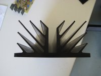
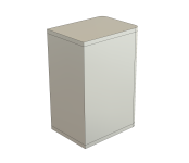
New Tapered Transmission Line Enclosure

In this blog post I also introduce a new tapered transmission line floorstanding enclosure for the FF165WK as a plan set that can be purchased downloaded on my site. This is also an area where I've improved in my ability over the past ten years. I believe the new TL enclosure maximizes the potential bass performance from this driver. Please contact me if you would like a custom enclosure designed for a specific driver.
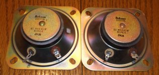
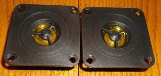
Super Tweeter

Over the past six months I've been spending a lot time on super tweeters. The FF165WK lends itself to the addition of a super tweeter by virtue of it's natural roll-off above 10kHz. The driver can be used alone, or with a high frequency driver using a range of crossover points ranging from 2kHz - 10kHz. In the context of the DIY enthusiast, the FF165WK can serve has a good test box to evaluate various high frequency solutions. Considering that the overall cost of the FF165WK driver is relatively affordable, the enthusiast just may have money left over for a super tweeter as well.
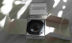
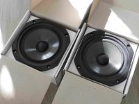
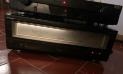
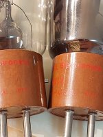
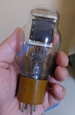
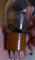
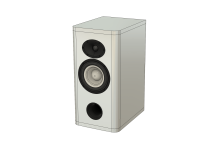
Appearance

For me I really like the appearance of the FF165WK with it's various shades of grey. It has a vintage look to it as well which some people really like.

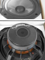
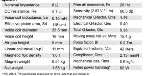
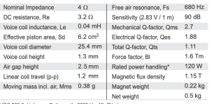
General Features of the FF165WK

The particular model stands out from the rest in that it uses a aluminum dust cap to extend the high frequencies as apposed to a whizzer cone. It's part of a family of FF series driver models which range in size from 3", 4", 6.50", and 8.00".

Features

  • Double layer cone
    • Pulp base layer with Kenaf top layer
      • Kenaf layer provides high speed sound propagation
  • Aluminum dust cap
    • Proprietary center dust cap ridge to distribute modal breakup
  • Low loss urethan foam surround
  • Relatively high sensitivity of 92dB/1w for a 6.50" woofer
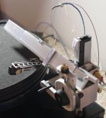
Measurements

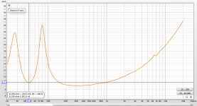
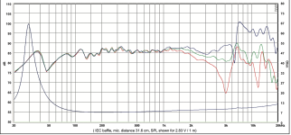
I measured the response at 1m mounted in a 20cm wide transmission line floorstanding speaker. I gated the measurement above 300Hz and then conducted a near field ungated measurement below 300Hz and spliced the two responses.

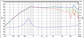
The on-axis frequency response can be summarized as follows.

  • Very high sensitivity through the midrange (95dB 1w)
  • +5dB rising response from 300Hz - 8kHz
  • -12dB/octave falling response above 8kHz
  • Surround resonance at 4.5kHz
  • Sharp +15dB resonance at 18.5kHz (outside audible band)
Fostex_FF165WK_1m_480x480.png


Comparison for Context

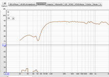
Below is the frequency response of the Markaudio CHR120 for comparison.

Markaudio_CHR120_480x480.png


If I overlay the Fostex FF165WK (Blue) for comparison we can see that the Fostex has significantly higher sensitivity. This is very important if using a low power amplifier since the amplifier is going to produce much less distortion at the lower output voltage. In this particular case the Markaudio will draw two times the power from the amplifier for the same output SPL. When looking at specific low power amps such as the Nelsen Pass Amp Camp Mini, this can be a distortion difference of 39dB in noise floor when comparing distortion between 1v output from the amplifier versus 4.00V (2w).

Markaudio_CHR120_Red_against_Fostex_FF165WK_480x480.png


Off-Axis


Below is the off-axis frequency response overlay for 0, 15, 30 and 45 degrees off-axis. The driver's directivity starts to narrow at around 5kHz. This can be observed by the blue line (30 degree off-axis) at the 5kHz region where things start to fall off as you move up in the frequency spectrum.
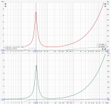
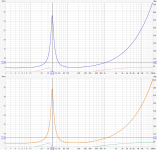
Fostex_FF165WK_0_15_30_45_Degrees_Off-Axis_480x480.png


Time Domain

Below is the burst decay out to 20kHz. The resonance at 4.5kHz is likely more audible due to the peak in the frequency response more than it's tail out to 12 periods. So if the peak is subjectively offensive then simply notching out this region is likely a good solution. The peak at 18.5kHz is entertaining to see.

Fostex_FF165WK_1m_20kHz_480x480.png


Extending the burst decay out to 50kHz highlights this resonance even further. We see full ring out to 24 periods. That's a big resonance! Luckily this is outside the audible band.

Fostex_FF165WK_1m_50kHz_BD_480x480.png


The CSD is surprisingly clean with the exception of the 4.5kHz surround resonance.
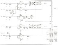
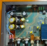
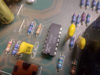
Fostex_FF165WK_1m_CSD_480x480.png


Correction Network

Based on the above test data it appears the driver performs well with the exception of the following...

  • Midrange peak at 1.5kHz
  • Resonant peak at 5kHz
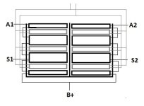
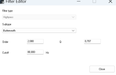
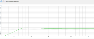
The below schematic is what I came up with the correct for the above issues. It is comprised of two series LCR contour circuits.

2286-schematic_blanked_out_480x480.png


Below is an overlay between the raw response (red) and the affect of the filter (green).

Fostex_FF165WK_with_Correction_Network_No.2286_480x480.png


I then re-measured the off-axis at 0,15, and 30 degrees off-axis.

Fostex_FF165WK_with_Correction_Network_No.2286_Off_Axis_0_15_30_480x480.png


Below is the time domain performance with the correction network in place.

Fostex_FF165WK_with_Correction_Network_No.2286_BD_480x480.png
Fostex_FF165WK_with_Correction_Network_No.2286_CSD_480x480.png


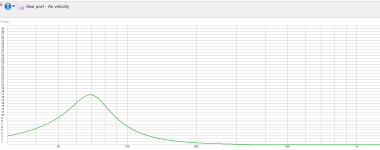
Bass Cabinet No.2286 -- Tapered Quarter Wave Transmission Line (TQWL)


Untitled_Project_4_b3593228-9b8f-44a1-ab20-e9c365db3cba_480x480.jpg


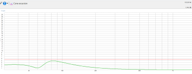
Below is the half space in-room response without the correction network. The speaker was placed about 30cm from the rear wall. No internal damping material was used in the enclosure.

Fostex_FF165WK_Half_Space_Transmission_Line_480x480.png


Untitled_Project_3_3c4c7939-8f12-4fce-9bb2-fb3621ea7e1b_480x480.jpg


Screenshot2023-11-09115833_d419c455-c4c9-4b75-9d3d-36df6d487c05_480x480.png
Screenshot_2023-11-09_120906_480x480.png
Screenshot_2023-11-09_120941_480x480.png
Screenshot_2023-11-09_120133_480x480.png
Screenshot_2023-11-09_120111_480x480.png

Missing low bass with ported?

Hey everyone.. I'm working on my 1st set of speakers. They are a set of bookshelves using the RS180-8.

The enclosures are about 12.5L and I put a 5.1cm port that's 18cm long. This should give me a Fb of around 47Hz. Based on WinISD this should result in a F3 or around 47dB.

On the impedance chart, it looks like the box is tuned to around 47Hz (assuming I'm reading it right), so that seems right. But when I do a near field measurement of the woofer on axis, the F3 seems more like 76Hz.

When I listen to music, it sounds like it has lots of bass, so I'm trying to understand if this is a measurement issue, or a real issue. If it's a real issue, what causes the early rolloff like that? Should I try to adjust the port to compensate?

Thanks.

Attachments

  • Screenshot 2023-11-14 at 12.05.02 PM.png
    Screenshot 2023-11-14 at 12.05.02 PM.png
    96.6 KB · Views: 104
  • Screenshot 2023-11-14 at 12.08.33 PM.png
    Screenshot 2023-11-14 at 12.08.33 PM.png
    35.9 KB · Views: 103

Seeburg PA4-L6 Schematic Needed--Broke Tube Socket Had to Replace!

Was recapping a Seeburg PA4-L6 when a pin broke off the 12BH7 socket. I am in the process of replacing the socket, however, the photos I took of the assembly before I started don't show where a couple of the capacitors connected to the socket, so I need to refer to the schematic.

It's a narrow, deep chassis with a lot of components crammed in there, and the stuff I needed to replace was in the bottom layer. I was struggling to disconnect a component from the socket when the pin broke. &^%$&^%$!

Just need the details of what hooks to the 12BH7 socket so I can put this back together.

Need Help on Amplifier Remote Tactile Switch

Hello,

My amplifier remote has gone bad. The volume + and - buttons are no longer tactile and it does not come up once pushed. I am planning to replace them and found exact same size tactile switch on Mouser.

https://au.mouser.com/ProductDetail/710-430182095816

My questions are;

1) Is the switch pretty much universal so can use this 12vDC switch as long as it fits in size or I need to somehow find out exact spec to replace with?
The remote takes 2 x 1.5v AAA batteries.

2) Is there specific orientation of the tactile switch that needs to be mounted (such as pin 1 is top left etc) or can be mounted either side as long as two lefts are facing side ways?

Sorry for novice questions and first time replacing tactile switch on remote and any help would be hugely appreciated.

Thank you.

Attachments

  • Remote Tactile Switch.jpg
    Remote Tactile Switch.jpg
    446.5 KB · Views: 85

Orchard Audio Showroom Open House - Nov 19, 2023 - Rockaway, NJ

Join us at the Orchard Audio Open House and experience the future of audio, where every note and sound is brought to life with precision and passion!

📆
Date: November 19th
🕒
Time: Noon - 4pm
📍
Location: 176 Franklin Ave, Rockaway, NJ 07866

What to expect:
🎵
Live demonstrations of our state-of-the-art audio technology.
🔊
Expert insights and Q&A sessions with our team.
🎉
Refreshments and networking with fellow audio enthusiasts.
🎁
Special promotions

Come and celebrate the beauty of sound with us! This open house is the perfect opportunity to get up close and personal with the latest innovations in audio.
Please RSVP at this link to ensure we can accommodate all guests.

Current Setup:
Source: PecanPi+ Streamer – $800
Amplifier: Starkrimson Stereo Ultra – $2650
Speakers: Soundfield Audio M1V2 – $2300 / pair
Cables: Triode Wire Labs
Room Treatment: GIK Acoustics

For more information please contact me here:
orchardaudio.com/contact or 504-233-3444

20231001_164859.jpg

Pair of unused bass/mid drivers Audax HM170Z2

Stock clean up: a pair of unused Audax Aerogel dual voice coil 17 cm bass/mid drivers (type HM170Z2)
Bought for a project which was never started (due to other priorities).
The units are packed in the original box and are not broken in.
Price: 170 euro plus shipping (preferably within EU)

Attachments

  • Foto_1.jpg
    Foto_1.jpg
    303.7 KB · Views: 71
  • Foto_2.jpg
    Foto_2.jpg
    230.5 KB · Views: 83
  • Foto_3.jpg
    Foto_3.jpg
    370.4 KB · Views: 84
  • Foto_4.jpg
    Foto_4.jpg
    287.5 KB · Views: 88
  • Impedance Speaker 1.png
    Impedance Speaker 1.png
    34.3 KB · Views: 80
  • Impedance Speaker 2.png
    Impedance Speaker 2.png
    32.5 KB · Views: 78

For Sale Europe : PSU PCB for Technics SL-1200 DC Power Supply

Hello everyone, from my Technics SL-1200 DC Power Supply project, I ordered the minimal quantity of 5 PCBs. One sold, I'm left with 3 pieces. Size 110x62mm, details and more pictures on my post in the original thread. Credits to 6L6 for the original design. I deliver the schematics with the PCB, no BOM, but it's easy, super-standard components and spacing, large space for soldering, wide tracks, room for 4 M3 screws at the edges.

Price delivered in continental Europe 13€.
PXL_20231112_132507839.jpg

For Sale Twisted pear Buffalo III multichannel set and miniDSP 2x4HD

Looking to sell the following items.

1) Twisted Pear Audio Buffalo III (ES9018) multichannel set.

Consisting of the following parts:


  • Buffalo III (ES9018) multichannel DAC board;
  • Trident Regulator set;
  • volume control;
  • IVY III linestage (assembled);
  • Placid HD-BP power supply;
  • LCDPS (assembled);
  • Toroidy 9V and 15V transformers;
  • 4 Channel S/PDIF 4 module;
  • Toslink optical input module;
Will also include Mercury IV stage which I got from another member here. It has flying leads attached, but those can be unsoldered.

Looking for 500AUD 450AUD (~290USD/270EUR) SOLD.

PXL_20230822_090329754.jpg
PXL_20230822_090145468.jpg
PXL_20230822_090237611.jpg
PXL_20230822_090301762.jpg
PXL_20230822_090210836.jpg
PXL_20230822_090438832.jpg

2) miniDSP 2x4HD

Comes with the power adapter, USB cable and remote.

Looking for 275AUD 250AUD (~160USD/150EUR).

PXL_20230822_084431510.jpg
PXL_20230822_084720919.jpg

  • Locked
Gerber File Revisions Needed

In the Pass HPA-1 thread "What Do We Know", a rar file for a clone board was attached in post #508 by @mokaonli. I have been trying to reach him by pm with no success. Is there someone who would be willing to make some small revisions to the Gerber file and also create a drill file? It is Jeff Young’s board but without the logic control, relays, and 5V power supply. I would be most happy to compensate in some way and I would so appreciate it. I am an old retired guy and don’t have the comprehensive skills to learn KiCad or similar. JLCPCB can make the board but they don't seem to understand the simple revisions needed and producing a drill file. I contacted PCBWay, but they want $450 to do some simple changes! But I do not know how much work is involved in a drill file so I may just have Jeff's board made.

https://www.diyaudio.com/community/threads/pass-hpa-1-what-do-we-know.300060/page-26

Soekris R2R DAC Project

Greetings,

Just thought I'd post my DIY DAC based on the DAM 1021 board from Soekris. While I have built several kits before (amps, preamps, phono stages, etc), this was my first attempt at something where I had to source my own components.

For the power suppy, I used a kit from Sparkos labs and paired it with their discrete voltage regulators. While some folks might call "snakeoil" on the idea of using expensive voltage regulators, I have had the privillege of owning two identical DACs in which one was using the Sparkos regulars and one with the stock regulators and I can say with confidence that they do make a noticable difference. As this was going to be a DAC for my main system, I wanted to use the nicest power supply I could afford since the PS was probably going to be the most important component (save for the DAC itself) in this project. The chasis was just a generic DAC chasis from Aliexpress and the TOS board came from DIYTHINK.

At first, I tried using the raw outputs from the DAC because I wanted to avoid using op-amps for output. While the sound was nicely transparent, it was lacking in energy and dynamics. I then switched to the buffered outputs and was much happier with the sound. That being said, I was still not entirelly satisfied. I looked into any other kind of buffer I could use, but was limited by space and my own knowledge. Then I reached out to the folks at Sowter and asked about using a transformer on the raw DAC outputs to get the output I wanted (2v or better). They suggested their 1461 transformer which, according to their calculations, would give me about 2.14v coming from 1.4v/625 ohms into a 10k load (the volume pot on my amp). I wired them in a noticed an immediate difference in the transparency and overall realism of the sound over the buffered (op-amp driven) outputs. It did seem to have a bit less drive/energy over the buffered outputs, but I was still much happier with the sound.

I'm not sure using that transformers to drive the output of a DAC would work for everyone in every circumstance, but they proved to be perfect for me. Hope this helps someone else!


PXL_20231007_203831054.jpg
  • Like
Reactions: manniraj

Difference in ohms

Hi guys, hope all are doing well

Recently I visited a speaker repair site for replacing my woofer cone and spider he said coil was good so he kept the same one

The woofer was 6ohms
Now comming home if I measure it, the meter shows 5ohms
Is this ok or will cause some big issue this decrease ohms will effect only one channel of amplifier and other channel speaker was not repaired just one channel speaker

What do you guys suggest

Thanks

Powered subwoofer for home theater system question

Hey guys! You know those powered subwoofers you can add to your home theater system? The one I have is a Cerwin Vega AVS-SUB8.

When I had a boombox style Sony stereo I used the speaker terminals to power the subwoofer, and I had some cabinets wired to the outputs. Since I had to replace that stereo I decided to make one with a car radio and an Smps from an old desktop computer.

If I try using the speaker terminals to power the subwoofer with my car radio/stereo, it doesn't work.

If I wire everything up and turn it on my radio doesn't make a sound. If I have the radio on and playing, I can hook up the subwoofer and it works fine. But If I turn the radio off and back on again, my radio won't make a sound. If I then disconnect the subwoofer while the radio is still on and playing (but not making a sound) the sound instantly starts playing again.

If I use the coaxial input it works fine.

The only thing I haven't tried is to use both the speaker terminals and coaxial inputs at the same time.

Could the 50W per channel that my radio makes be too little to power the subwoofer? If that were the case, wouldn't it just be quieter, not silent?

I already opened up the SUB8 and moved the little "jumper" from the (Auto) prongs to the (On) prongs, but that just makes it so the subwoofer doesn't go into sleep mode when the radio shuts off and did not fix the problem.

Also, do the coaxial cables act like speaker wires? By that I mean If I use piggyback coax cables to power several of the same powered subwoofer, either in parallel or series, will that effect ohms or anything? Or what about the same scenario except I use the input/output speaker terminals to power several of the same subwoofers?

Any suggestions will be appreciated!

Passive crossover parts in active speaker system? Possibilities of hybrid crossover

Hi,

I've been using DSP crossover for my loudspeaker projects as its very flexible and cheap to experiment with prototypes, doesn't mind driver impedances, sensitivities, can do delay, flat response etc. in general mucho flexibility, what ever is the requirement. Alright, please lets not get too deep into whats more expensive or cheap or laborous complicated or sounds better as there are million threads already for this kind of debate.

I've never dug deep into passive crossovers but I can see advantages outside from making some hi/lowpass slopes and notch filters. For example I use L-pad for compression driver to reduce (amplifier) noise along with a capacitor to protect it from mistakes. Quite cheap parts and effective results but doesn't necessarily have nothing to do making actual crossover happen, I've got DSP for it.

There seems to be some more, like adding inductor in series with woofer to reduce impedance variation when BL changes with excursion, or something along the lines, reducing distortion. Joe Rasmussen seems to write about it a lot. I've also seen big series capacitor used series with a woofer, which can change Q of the system and provide some boost allowing using somewhat smaller enclosure (sealed). Anyway, I'm not too deep into this but clearly there seems to be advantages with passive parts, outside of forming filtering as such.

What I'm interested in is get more info about good and bad things using passive crossover parts in active speaker systems, how to use them and what for? Have you used any and why? If you have only passive crossover implemented, what duties your crossover does in addition to just making acoustic slopes and filters happen?

Perhaps all of it is covered in some xo basics readings, didn't come up to one yet 🙂
  • Like
Reactions: vineethkumar01

Some questions on using an LL1540 for unbalanced to balanced conversion

1. I believe I can use this wiring diagram for the LL1545e on this transformer? https://www.lundahltransformers.com/using-the-ll1545e/

2. How do I know if I still need the capacitor/resistors on the LL1540 output?

Link to LL1540 datasheet for reference: https://www.lundahltransformers.com/wp-content/uploads/datasheets/1540.pdf

Thanks for the help.

PS. I’ll be using the transformer on the input of a BPA300 with 47kohm resistor on the input.

Help Needed Technics SE-A909S

Greetings to diyAudio community!

So I've made a huge crap today!
Needed to change some electrical plugs behind my hi-fi Technics system but had my mind elsewhere and forgot to unplug it before so I had it on standby.
What happened was, when removing the power amp controller (SU-C909u), I've disconnected the cable that links it to the power amp that was on standby and when removing it the amp turned on immediately and I could hear the little feedback from the speakers from the working amplifier.
I've then disconnect everything and made the necessary changes.
When putting everything back together the amp didn't worked anymore.
Turning it on, only the left lamp from the meters turns on, the led "operation" comes on after a second as it should but no sound, no movement from the meters as well, its virtually dead 🙁
Any Technics maintenance guru out there with some guidance helping me to bring it back to life?
I would be very thankful
Cheers

Attachments

  • Captura de ecrã 2023-10-24, às 21.59.23.png
    Captura de ecrã 2023-10-24, às 21.59.23.png
    871.9 KB · Views: 97

PP output transformer sanity check

Hello everyone,

I'm planning to make PP output transformer for UL KT88 amp. Nothing new, +470-480V B+, UL, around 4.5k Ra-a.

What I have at hands now - M6 EI 120-53 lams, split bobbin.

Windings in one bobbin's half - 1/2 P-S-P-S-P-S-1/2P (4 primary, 3 secondary)

where 1/2P is 3 layers (74 turn each) and P - 6 layers (74 turns)
Secondary(S) is 4 layers: 2 layers(114 turns)+2 layers(114 turns) in parallel = 114 turns in one section

All secondary sections also in parallel (both halves of bobbin)

Overall - 2664 turns primary, 114 sec. , so Ra-a is ~4.4k (without considering DC resistance, just turns ratio). Other data - ~160 Ohm primary(80+80), ~0.32 Ohm secondary.

Main question - will it be OK as is, or cross-connection of primary windings is necessary? Any advice would be appreciated.

Attachments

  • OT.jpg
    OT.jpg
    17.3 KB · Views: 94

Replacing Burnt Components on Gallien Krueger RB400 Bass Amp

Hi all,

I recently acquired a Gallien Krueger RB400 (schematic / service manual here) which has a few burnt components on the power supply board (see attached image). R28 looks especially toasty. Which components should I replace before powering up? Is the fault likely a bad output transistor (Q11)?

Any help is greatly appreciated.

Attachments

  • IMG_20180113_154338.jpg
    IMG_20180113_154338.jpg
    1,009.4 KB · Views: 499

Mark Levinson ML10A recap

Hello! Just bought a ML10A as a secondary preamp for my hifi system (using mainly my ML no.26 and a GAS Thaedra). The preamp inside looks totally untouched, and as I supposed when I open the psu cover one of the power supply caps had a leak. The preamp works fine but I have to recap that old machine ! Does anyone have the service manual of it? I search around the net with no hope 🙁 . Do I have to re-adjust something after doing the recap? Best regards!!!

Attachments

  • IMG_1764.jpeg
    IMG_1764.jpeg
    588.5 KB · Views: 159
  • IMG_1763.jpeg
    IMG_1763.jpeg
    543.4 KB · Views: 119
  • IMG_1762.jpeg
    IMG_1762.jpeg
    431 KB · Views: 111

Suggestions for Improvement?

Hi All,

I was on this forum years ago and have been building tube audio amplifiers for a while now but am still learning. So I want to share a current project and ask for some suggestions on how I can improve its high-frequency performance.

The backstory:

After a jig of working mainly with small signal tube amplifiers (preamps, phono stages, etc.), I decided to take a stab at a power amplifier with toroidal power and output transformers.

The transformers I purchased were part number VDV-4070-CFB-PPS from Bureau Vanderveen. According to their published specifications, they looked like very good units. Their wide bandwidth is primarily what sold me.

https://www.mennovanderveen.nl/index.php/nl/producten/specialist/vdv-4070-cfb-pps-detail

Having no experience with this kind of transformer, I made the following circuit:

Schematic2.png


Schematic.png

This is a markup of a partial schematic. I only am showing the audio circuit and not the microprocessor control circuitry (as it is not relevant). The markings are what I did to improve the performance already. Purple markings show DC voltages. Red markings are circuit and component value tweaks. Cross-outs are in blue.

Measurements:

All measurements were taken with a an 8-ohm resistive dummy load hooked to the speaker output. Measurements were taken with an H8903B audio analyzer, a Siglent SDS2204X oscilloscope, and a Fluke 287 multimeter. Square wave plots were generated by a BK Precision 4045B waveform generator. VRMS measurements were taken just before the amplifier clipped. Nominal power output is 50 watts into 8-ohms.

1. Open loop frequency vs. gain plot.

FrequencyVRMSGainGain (dB)
20​
16.5462987​
165.462987​
44.3740172​
50​
19.0918831​
190.918831​
45.6169753​
75​
20.0111219​
200.111219​
46.0254288​
100​
19.9404112​
199.404112​
45.9946822​
500​
20.0818326​
200.818326​
46.0560668​
1000​
20.0818326​
200.818326​
46.0560668​
5000​
19.9404112​
199.404112​
45.9946822​
10000​
19.6575685​
196.575685​
45.870596​
15000​
19.0918831​
190.918831​
45.6169753​
20000​
18.243355​
182.43355​
45.2220942​

1698622573071.png


2. Closed loop frequency vs. gain plot along with THD:

FrequencyDistortionAmplitudeAmplitude (dB)
20​
3.15​
21.16​
26.51031327​
25​
0.32​
20.89​
26.3987688​
30​
0.25​
20.91​
26.40708066​
50​
0.23​
20.73​
26.33198604​
75​
0.25​
20.7​
26.31940691​
100​
0.23​
20.67​
26.30680953​
250​
0.24​
20.66​
26.30260634​
500​
0.25​
20.67​
26.30680953​
750​
0.25​
20.66​
26.30260634​
1000​
0.26​
20.66​
26.30260634​
5000​
0.57​
20.52​
26.24354713​
7000​
0.78​
20.42​
26.20111476​
10000​
1.04​
20.23​
26.11991766​
15000​
1.7​
19.7​
25.88932452​
20000​
2.3​
19.2​
25.66602457​
30000​
3.67​
17.81​
25.01327839​
50000​
5.87​
14.37​
23.14913536​

1698622763498.png


1698623444328.png


Questions and Observations:

The current driver I am using rolls off open loop starting around 10kHz or so. I observed the tubes are the main contributor to the rolloff and not the transformer. So naturally the GFB loop, when introduced, increased the gain more at higher frequencies with respect to the lower frequencies. Distortion increased due to the higher gain. What do you suggest I do to improve the performance of the open-loop bandwidth? Are there better driver circuits I could look at using?

I have more questions but will save them for another post.

Thanks very much.

Driver selecton help.... Small Open Baffle with Faital Pro 15PR400

I have a new pair of Faital Pro 15pr400 4 Ohm that I bought for a different project, and am now wondering if I should sell them, or make something new.

I was interested in the idea of making a "small" open baffle with them, using minidsp for the crossover, to be played at low to mid levels.

Anyone have any suggestions for a tweeter to match with? I want to keep it relatively simple and small.

I am aware of this... but it doesn't interest me...

OBL-15

I was thinking maybe a BG Neo 3 (or 8), maybe a Aurum Cantus G3Si, maybe Heil AMT... open to ideas!

Thanks.

Dynacord PowerMate 1600-3 & KV2 Audio ESD15

Hello everyone,

I have recently purchased Dynacord PowerMate 1600-3. Can someone please tell me this mixer would work well (or maybe not at all) with KV2 Audio ESD15? Here are the basic specs for both:

1. Dynacord PowerMate 1600-3

2x 1000 W/4 Ohm RMS
2x 600 W/8 Ohm
2x 1350 W/2.7 Ohm
6 Mic/Line XLR inputs with 3-band semi parametric EQ
4 Mic-/Stereo line combi-inputs with 3-band-EQ
2x 24-Bit stereo effects processor with fixed presets, plus editable and storable user presets
2x FX/AUX for internal effects device
2x AUX Pre/Post switchable
2x Monitor AUX (pre)
Mute per channel
Switchable 80 Hz low-cut
Switchable Voicing Filter per XLR input
Feedback filter for MON 1-2
New 11-band EQ routed to the master channels
B-Master output for recording or mono subwoofer, etc
USB Interface for music playback or output for recording applications (up to 4 tracks at the same time)
Integrated Midi interface in/out
Switched-mode power supply
Integrated loudspeaker protection
Speaker Twist outputs
Volex mains input

2. KV2 Audio ESD15

2.1. System Acoustic Performance
Max SPL Long-term 126dB
Max SPL Peak 132dB
-3dB Response 48Hz to 18kHz
-10dB Response 45Hz to 28kHz
Recommended Power 500W
Sensitivity 97dB
Impedance 4Ω
Crossover Point 500Hz, 2.5kHz

2.2. High Frequency Section
Acoustic Design Horn Loaded
High Horn Coverage Horizontal / Vertical 80° x 60°
Throat Exit Diameter / Diaphragm Size 1" / 1.75"
Diaphragm Material Nitride Titanium
Magnet Type Neodymium
Protection Electronic RMS and Peak Limiter

2.3. Mid Range Section
Acoustic Design Horn Loaded
Mid Horn Coverage Horizontal / Vertical 80° x 60°
Woofer Size / Voice Coil Diameter / Design 6" / 1.5"
Diaphragm Material Epoxy Reinforced Cellulose
Magnet Type Neodymium
Protection RMS Limiter

2.4. Low Frequency Section
Acoustic Design Front Loaded, Bass Reflex
Woofer Size / Voice Coil Diameter / Design 15" / 4"
Diaphragm Material Epoxy Reinforced Cellulose
Magnet Type Neodymium
Protection RMS Limiter

2.5. Speaker Input
Speaker Input 2x Neutrik Speakon®, Terminal Block

I am also open to suggestions for any other 3-way passive loudspeakers. They would be used in small indoor and outdoor settings.

I appreciate any advice!

Rufad

I have a passive subwoofer need low pass filter

So I am thinking to connect 220uf capasitor it might block high and allow low frequency to pass


My subwoofer specs
Bass Enhancer, Flat Cap. 5,25 Inch Low frequency (40Hz to 160Hz) driver with Amplifier sub out/Low pass filter connection. Full Range Driver with 15W direct Car Head output. 6.5cm depth required to use in car door pad. Best for home theatre stock driver

For Sale Genuine Tripath evaluation board RB-TA3020 with power supply PCB

Hello I have 3 Tripath evaluation board RB-TA3020 for sale at 76€ if you need power supply pcb
Included Sanken rectifier bridges and connectors is 18€.
Here populated power Supply shown as an example
Tracked shipment shipping to US on request.
Payment by paypal
1670165426830.jpg

Attachments

  • 1670165426826.jpg
    1670165426826.jpg
    462.2 KB · Views: 154
  • 1670165465030.jpg
    1670165465030.jpg
    476.5 KB · Views: 134
  • 1670165465023.jpg
    1670165465023.jpg
    403.6 KB · Views: 141
  • 1670165426819.jpg
    1670165426819.jpg
    433.9 KB · Views: 147

diyAudio-store offline

I cannot reach your site today -- anything "untowards" happening?

$ dig diyaudiostore.com

; <<>> DiG 9.18.12-1ubuntu1.2-Ubuntu <<>> diyaudiostore.com
;; global options: +cmd
;; Got answer:
;; ->>HEADER<<- opcode: QUERY, status: NOERROR, id: 48071
;; flags: qr rd ra; QUERY: 1, ANSWER: 1, AUTHORITY: 0, ADDITIONAL: 1

;; OPT PSEUDOSECTION:
; EDNS: version: 0, flags:; udp: 512
;; QUESTION SECTION:
;diyaudiostore.com. IN A

;; ANSWER SECTION:
diyaudiostore.com. 300 IN A 23.227.38.65

;; Query time: 52 msec
;; SERVER: 8.8.8.8#53(8.8.8.8) (UDP)
;; WHEN: Mon Nov 13 15:46:20 EST 2023
;; MSG SIZE rcvd: 62

$ date
Mon Nov 13 03:47:21 PM EST 2023


There was a problem loading this website
Try refreshing the page.

If the site still doesn't load, please try again in a few minutes.

Refresh Page

Elekit TU-8100 project

Hello,

New member from Italy. A friend of mine purchased an Elekit TU-8100 kit from a japanese ebay vendor, instructions in japanese. He never got around to building it. He proposed to sell the kit and I accepted. He works elsewhere, so he will bring the item in a couple of weeks or so.

In the meantime have been browsing this forum and I found tons of useful information.

I have already bought two fostex full range desktop speakers, P800E, I received and assembled them. That was easy

I have no experience at all on building a vacuum tube amp. I studied on several sources online, I bought soldering kit, 0.5 mm 63/37 solder, magnifying glass with led lamp, tools. I also found a video where a Canadian man builds the amp with japanese instruction. So I studied the video.

But the instructions are in japanese. I'm a bit worried. I was wondering if some of you who built this amp could take a picture of the english instructions and private message me.

I fear that this request could come across as unfair to the north american Elekit dealer because this friend of mine bought the kit in Japan. If it is so, i do apologize. But I'm a newbie and are a little bit uneasy.

Sorry again if the request offended someone.

Regards,

Patrizio.

VFET-X (or my 1/3 40th Anniversary Sony VFET Clone)

I always wanted to build a last special amplifier, and wanted it to be big and spectacular.
My big example is the '40th Anniversary Sony VFET Amplifier' Nelson presented at CES in 2014.
There are more members who told me they also want to build something like this so I opened my first thread 🙂
I will post a lot of pictures...
What I like to try is building a stereo version of this amp with 1/3 of the VFET's so 8 per channel instead of 24.
Then bias each a bit higher to get a 1/2 40th Anniversary Amp😀

The schematic is the original Sony VFET pt2 article with the two VFET's paralleled and then double it to get a fully balanced amp.
Both sides are connected with R24 to each other instead of to ground.

I will make my own PCb's, chassis and so on, just having a lot of fun.

On Ebay I found this nice Pass like heatsinks, so I will build the whole amp in a kind of XA160 chassis.
The heatsinks are 'Oxidised' according to the seller, is that different to 'Anodised'? Does somebody know?
They feel different and look more shiny than what I'm used to.
I tested one heatsink with around 100 Watts on the surface, but the surface was too rough, brushed, to get good results. After removing the black 'oxidized' layer and a lot of smooth sanding they transfer the heat better.
I estimate each heatsink can do about 80 Watts of heat. I have six of them so total of 480 Watts. I hope 😱

Attachments

  • 40yearBIG.jpg
    40yearBIG.jpg
    284.5 KB · Views: 3,577
  • Big-Sony-DIY.jpg
    Big-Sony-DIY.jpg
    133.3 KB · Views: 3,508
  • NG7_Pass_VFET.jpg
    NG7_Pass_VFET.jpg
    251 KB · Views: 3,612
  • sinks-arrived.jpg
    sinks-arrived.jpg
    325.6 KB · Views: 3,286
  • sink-top.jpg
    sink-top.jpg
    200.7 KB · Views: 3,142
  • sink-brushed.jpg
    sink-brushed.jpg
    244.8 KB · Views: 1,057
  • sanded.jpg
    sanded.jpg
    251.1 KB · Views: 1,247
  • heat transfer.jpg
    heat transfer.jpg
    297.7 KB · Views: 1,455
  • 100Watt.jpg
    100Watt.jpg
    311.7 KB · Views: 1,378
  • after-sanding.jpg
    after-sanding.jpg
    376.3 KB · Views: 1,057

Layout of crossover help please

I have a crossover schematic and also have the parts on hand. Its a 2 way design. Crossover will be mounted on a wood board and soldered underneath for looks. I want to put both the HF and LF crossover on same board if possible.

I need some help in the layout. I know to keep the inductors at angles if they are close.

Looking for something that visually looks good also.

I can post the schematic if needed.

Thanks!!

Driving Active Speakers from a Behringer Powered Mixer PMP560M

I have active speakers that I need to use with a powered mixer ( Behringer PMP560M). It has no signal outputs but I suspect that the output maybe BTL. Therefore the usual circuits are no good as they are designed for a traditional single ended amp & will short a bridged amp.

Before I tackle the detailed design work, has anyone seen or designed such a circuit?

For Sale 985 NOS International Rectifier IRFP9240 P-Channel MOSFETs

SOLD

These have been in storage for 20-ish years and some of the antistatic tubes have yellowed. There are 39 tubes of 25 pieces, plus another partial tube of 10.
Listing these as a lot for $1000 in the off chance someone has a really BIG project, or wishes to create matched sets for resale.
IRFP240 (N-Channel) ones are in a separate listing.
20231108_080515.jpg

20231108_080549.jpg

20231107_081127.jpg

20231107_080522.jpg

For Sale 1,400 NOS Fairchild IRFP240 N-Channel MOSFETs

SOLD

These have been in storage for 20-ish years and some of the antistatic tubes have yellowed. There are four boxes of 300 pieces, plus another 200 in loose tubes.
Listing these as a lot for $1000 in the off chance someone has a really BIG project, or wishes to create matched sets for resale.
IRFP9240 (P-Channel) ones are in a separate listing.
20231112_155003.jpg

20231112_155021.jpg


20231112_155206.jpg

20231112_163127.jpg

Affordable Ferrofluid for Canadian DIY folk

It all started with tearing down and rebuilding a set of beautiful old KEF 104.2's (with questioning side-glances at my Ditton 44's)...

Care to help me test-run a brand new website that is set to distribute ferrofluid at an affordable rate in Canada come Dec.?

I hope that this is not verboten on this forum; if it is, I'll understand and remove it with apologies...

I've created this site myself, with potentially questionable editing skills, so any positive feedback would be appreciated.

www.speakerferrofluids.com

For us DIY Canucks, accessing ferrofluid to rebuild drivers is practically impossible / unavailable in-country (which is bizarre) unless we ship drivers to technicians to do the work for us. I communicated with speaker repair shops in Vancouver, Montreal and Toronto ~ if I was not keen to send them my drivers for repair, they did not seem at all inclined to send me ferrofluid to do it myself...

Ferrofluid is absurdly expensive to bring in from elsewhere; case in point; today's currency conversion rate ($1.00 USD = $1.38 CAD) / ($1 EURO = $1.48 Canadian Dollar) and shipping costs for ferrofluid makes it somewhat akin to liquid gold! All of the several dozen sources that I looked at in Europe and America were more than willing to send ferro' to Canada, but only via courier or some expensive version of Royal Post :-(

This situation finds those here in the Great White North facing invoices of roughly $60 CAD to receive very small packets of ferrofluid!

In partnership with the world's largest ferrofluid manufacturer, Ferrotec ~ who have been great to deal with, my plan is to change this foolishness... come Dec., DIY Canucks can rejoice at access to affordable ferrofluid products, shipped nationally.

Thank you in advance for your input.

Andrew Drouin


BTW: Oddly, Bit Defender gives SSL warnings with I load the website with Microsoft Edge, while both Google Chrome and Firefox load it flawlessly... Something to look into going forward, prior to the Dec. roll-out.
  • Like
Reactions: rsavas

First Watt M2 Noise

I am getting some noise from my First Watt M2. It is noticeable on higher frequency compression drivers on a 800 hz. cutoff horn. So, the driver is VERY efficient and I don't think this noise would even be noticeable on typical efficiency speakers. But, high efficiency is what I use. I tried plugging the M2 into a power conditioner and no change. I don't think it's power supply hum, it's too high frequency. I also allowed the amp to warmup for several hours.

I have read about using a resistor and L-pad to bring amps up out of a noise floor. I do not know how to design this. Anyone tried anything like this with the M2? Any tweaks?

I love the amp and I fully embrace the zero feedback Class A design, so this is not a criticism in any fashion.

Cheers,

Jamie

For Sale A pair of 801A DHT tubes

SOLD NOW
A pair of National Electronics 801A from the same lot number, in their original larges boxes.
185USD shipped to most parts of the world registered+tracking. PayPal FF only please.

Attachments

  • 20231112_112937.jpg
    20231112_112937.jpg
    331.5 KB · Views: 74
  • 20231112_113012.jpg
    20231112_113012.jpg
    422.5 KB · Views: 71
  • 20231112_113130.jpg
    20231112_113130.jpg
    277.4 KB · Views: 82
  • 20231112_112627.jpg
    20231112_112627.jpg
    384.9 KB · Views: 81
  • 20231112_112813.jpg
    20231112_112813.jpg
    410.9 KB · Views: 85
  • 20231112_112700.jpg
    20231112_112700.jpg
    331.2 KB · Views: 79
  • 20231112_112654.jpg
    20231112_112654.jpg
    252.4 KB · Views: 80

SB17CAC35-8 and SB26ADC-C000-4 two way project

Hi everyone,

I'm planning to build a set of bookshelf speakers using the SB17CAC35-8 midrange driver and the SB26ADC-C000-4 tweeter (+wave guide), cross at ~1300 Hz. My goal is to build speakers that sound clear and crisp in the mid/high-frequency ranges for casual acoustic music listening in a medium/small-sized room. This time, I've decided to invest more time and effort into planning and building the right enclosures. The speakers will be connected to a Topping PA5 II plus 4Ω amplifier.
I have a few questions that I hope you can help me with:
  • I used WinISD to simulate the box volume and tuning frequency. Can you please take a look at the attached screenshots and let me know if there are any issues with the box design?
  • Do the cutoff and tuning frequencies make sense for a pair of speakers?
  • Do I still have some low frequency to enjoy?
I'm planning to tune the box to 60Hz with a volume of 15 liters and a high-pass filter cutoff frequency of 80Hz.

I will keep updating this thread

Thank you for your help!

Attachments

  • air_velocity.png
    air_velocity.png
    11.2 KB · Views: 134
  • cone_excursion.png
    cone_excursion.png
    10.7 KB · Views: 157
  • filter.png
    filter.png
    2.8 KB · Views: 132
  • portgain.png
    portgain.png
    8.7 KB · Views: 133
  • SB17CAC35-8 .png
    SB17CAC35-8 .png
    225.2 KB · Views: 134
  • SB17CAC35-8 specs.png
    SB17CAC35-8 specs.png
    102 KB · Views: 137
  • SB26ADC-C000-4 specs.png
    SB26ADC-C000-4 specs.png
    79.2 KB · Views: 132
  • SB26ADC-C000-4.png
    SB26ADC-C000-4.png
    197.3 KB · Views: 139
  • tfm.png
    tfm.png
    9.5 KB · Views: 146
  • Screenshot 2023-10-31 at 20.54.37.png
    Screenshot 2023-10-31 at 20.54.37.png
    65.7 KB · Views: 153
  • Screenshot 2023-10-31 at 20.54.43.png
    Screenshot 2023-10-31 at 20.54.43.png
    37.3 KB · Views: 162

Schematic diagram for Mordaunt-Short MS309-W

Can anyone supply, or tell me where I can get, a schematic diagram or Service manual for the above, please. A U.K. source for spares would also be helpful.
The 1.6AT fuse in the mains input blows in one I'm trying to repair, and none of the usual suspects(Rectifier, Filter Capacitors, etc.,)are faulty. Prior to the fuse blowing, the amp. would cut out if the volume was advanced more than about 60%, with only a 'signal' from my finger on the line level i/p present
Could the mains transformer have shorted turns??
Projects by fanatics, for fanatics
Get answers and advice for everyone wanting to learn the art of audio.
Join the Community
507,483
Members
7,873,699
Messages

Filter

Forum Statistics

Threads
405,557
Messages
7,873,699
Members
507,483
Latest member
kuttisrank