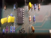
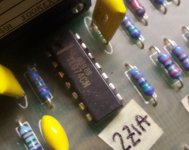
HI, I bought an analog electronic crossover, i.e. non-dsp, Rane Ac23.
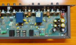
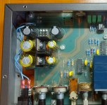
It has a couple of power caps that are a little swollen, so I wanted to change the 6 power caps there.
The power supply has a voltage multiplier. 10.5+10.5vac enter the crossover (external transformer) which are multiplied by two and then pass through the 7815 and 7915 regulators. The crossover operates at dual voltage +-15vdc.
Do you think I can use Panasonic FC for all 6 capacitors even if in different positions?
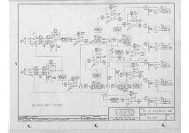
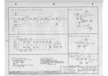
I attach the diagram.
I ask because I seem to have read that low ESR capacitors, downstream of the regulators in question, can generate oscillations or, in any case, not be optimal.
Also I wanted to ask why the TL072s are on sockets and the other OPs are not.
I would also like to upgrade the OP, many years have passed since its production and perhaps there is something better.
Does it make sense to just change the TL072s on the sockets? Or would it be necessary to also put sockets on the other dip14s and mount other OPs?
I would also like to eliminate the subsonic and ultrasonic filter.
I attach the diagram.
Thanks for any help.
Attachments
-
 ALIMENTAZIONE.jpg92.4 KB · Views: 291
 -
SCHEMATIC 01.pdf978.7 KB · Views: 171
-
SCHEMATIC 02.pdf884.1 KB · Views: 139
-
 20231108_153756.jpg535.9 KB · Views: 246
 -
 20231108_153811.jpg347.1 KB · Views: 244
 -
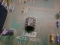 20231108_153819.jpg342.6 KB · Views: 249
 -
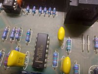 20231108_153826.jpg374.4 KB · Views: 227
 -
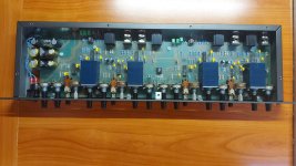 20231108_153842.jpg344.5 KB · Views: 373
 -
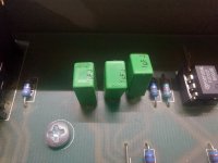 20231108_153848.jpg312.5 KB · Views: 230
 -
 20231108_153903.jpg335.2 KB · Views: 228
Does it work? If so start using it instead of tinkering with it.
TL 072 is good enough, Midas consoles used them in XL3 and 4, famous live consoles.
Just my 2 cents.
TL 072 is good enough, Midas consoles used them in XL3 and 4, famous live consoles.
Just my 2 cents.
Thanks for the reply, yes of course it works.
I may not even touch the opamp but I have to change the capacitors.
Furthermore I would like to remove the subsonic and infra filters. I use it at home.
Can you give me some help?
Thank you
I may not even touch the opamp but I have to change the capacitors.
Furthermore I would like to remove the subsonic and infra filters. I use it at home.
Can you give me some help?
Thank you
Thanks again, I'll follow your advice then. I will only change the 6 capacitors. Regarding their choice, are the Panasonic FCs good? considering the diagram and the voltage multiplier? Thank you
@justanalogue
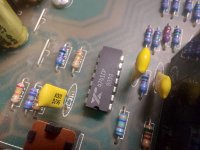
HI, I wanted to ask you for help, if you are available. I noticed that one of the quadruple operational amplifiers has been replaced with a TL074.
Originally there was one like all the others, namely a 4741cp.
Apart from the 4741cp there are TL072 (double OP), these on sockets.
As per the diagram, the TL072 are used for input and output.
The TL072 at the input is used partly as an input stage and partly as a subsonic high-pass filter at 20Hz (as per the user manual and declared specifications.
The TL072 is also on the outputs, I think they say it works as a "buffer". Maybe I'm wrong.
In fact there are 3, being 3 ways...6 exits.
So, in total, there are 5 TL072s. Three used for the 6 outputs and two used for the two inputs + two subsonic filters.
Going back to the problem of the TL074 instead of the 4741cp.... From the diagram this opamp works entirely on one channel (right) and therefore I find the asymmetric crossover! This is certainly not a good thing.
The crossover is 30 years old (maybe 40!). There will also be better opamps.
I would like to intervene to have all the operational amplifiers, obviously the same.
I would like to mount the sockets for them too and choose which op amps to mount.
The datasheet says that the 4741cp is a differential op amp, which it doesn't say about the TL074.
Is this serious?
I wanted to ask you if you could advise me which quadruple operational amplifiers to mount that are clearly compatible with the scheme and with what they are called to do.
I wouldn't want OPs other than the originals to make the crossover work badly, I don't know... maybe with different cuts from what I set with the knobs!
Thanks for any help. I am not very expert in electronics and therefore I am not able to move with absolute certainty.
I do have a good desoldering station though. It takes me very little to plug the integrated circuits.
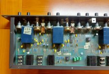
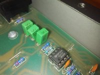
I attach some photos of both the original ops and of the TL074 which has been replaced with an original. not good! not good!
I also attach the diagram. When you look at it, if you look at it (!), remember that the input and output OPs are the TL072. All the others are 4741cp + a TL074 intruder (which I don't know if it's differential or even if this fact is important or not in this circuit).
Attachments
- Home
- Source & Line
- Analog Line Level
- Restore and upgrade crossover Rane AC23
