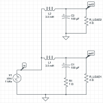
Assume we have two speaker series, Mk1 and Mk2. The woofer low-pass filters on these two speakers are identical; the only difference is the presence of a 1 Ohm resistor connected to the 100uF capacitor. The circuits are depicted below. Mk1 components are labeled "1" in their names, as are Mk2 components.

Let us now simulate the results in frequency domain to see the frequency and phase response of these crossovers. The results are shown below.
Frequency plots:

Phase plots:

As can be seen, the frequency curves are nearly synchronized, which is used for the woofers below 400Hz--the crossover point for these woofers assumes they are 3-way designs. So do the phase curves.
My question is, what is the point of installing the 1 Ohm resistor in the Mk1 speaker when the effect, phase adjustment, occurs outside of the woofer's operating range?

Let us now simulate the results in frequency domain to see the frequency and phase response of these crossovers. The results are shown below.
Frequency plots:

Phase plots:

As can be seen, the frequency curves are nearly synchronized, which is used for the woofers below 400Hz--the crossover point for these woofers assumes they are 3-way designs. So do the phase curves.
My question is, what is the point of installing the 1 Ohm resistor in the Mk1 speaker when the effect, phase adjustment, occurs outside of the woofer's operating range?
Last edited:
Adding the resistor lowers the driver's effective motor strength (raises its Qts spec), so definitely affects the driver's operating range defined by its upper mass corner frequency (fhm) = 2*Fs/Qts'
(Qts'): (Qts) + any added series resistance (Rs)
(Qts'): (Qts) + any added series resistance (Rs)