Can ceramic caps be used in line level audio?

Hi,

Ceramic caps change with time (aging) and thus are not considered good for audio line level application. After all, we dont want a filter
whose corner shifts with age.
A friend of mine who has good experience in electronics was of opinion that if SMD ceramics are used at a voltage lesser than 1/3 of their
rated voltage then they don't change the value with age and thus can be used for audio crossover.

Whats your opinion? Are new SMD ceramics usable in this application?

Regards,
WA

SAB - class AB 2x50W/4ohm amplifier with SMPS

Small class AB 50W/4ohm amplifier with SMPS (Gerber files added - see page 2) or linear supply

This amplifier is based on Kenwood KA-5010 circuit topology, class AB with 3EF output stage and 2-pole frequency compensation, which promises to keep low distortion even at higher frequencies. I was curious how it would work and built a 1st sample 5 years ago, followed by change of the linear power supply to SMPS's this year – resulting in a considerable loss of amplifier weight 😉.

Gerber files have been released in post #25 for non-commercial, non-profit personal use
https://www.diyaudio.com/community/...-4ohm-amplifier-with-smps.386169/post-7022262

This is the circuit schematics

ka5010clone_sch.png


As a power supplies I used Mean Well RS-100-24 modules, one per channel. This is the amplifier DIY built in one of my prototype cases

SAB_amplifier.JPG

Technical parameters
  • input impedance 90kohm
  • voltage gain 30dB
  • output noise voltage 22uV/20Hz-22kHz unweighted
  • output power 2 x 50W/4ohm
  • THD < 0.002%/40W/1kHz/4ohm
  • THD < 0.003%/40W/10kHz/4ohm
  • minimum load impedance 2.5ohm
  • frequency response 10Hz – 100kHz/0.2dB/4ohm

Measurements of THD and THD+N vs. output power, with 4ohm load

SAB_thdnpow_1k.png


SAB_thdnpow_5k.png


SAB_thdnpow_10k.png


Measurement of THD and THD+N vs. frequency at 20W/4ohm

SAB_thdnfreq_20W.png


Distortion spectrum

SAB_spectrum_1k.png


LTSpice files

P.S.: the amplifier has been re-measured with linear power supply 2x25Vm post #50, https://www.diyaudio.com/community/...-4ohm-amplifier-with-smps.386169/post-7031738

Attachments

  • SAB_cirsim_ltspice.png
    SAB_cirsim_ltspice.png
    49.1 KB · Views: 590
  • SAB_loopgain_ltspice.png
    SAB_loopgain_ltspice.png
    9.2 KB · Views: 739
  • SAB_kenwood.zip
    SAB_kenwood.zip
    5.7 KB · Views: 186
  • Like
Reactions: dreamth

Quad 405 PCB's & transistors.9 pairs of Genuine Sanken 2SC3858/2SA1494 Y + Mica's UK

For sale -
1) A pair of Quad 405 PCB's + 5 2N3773 & washers/insulators + 4 MJE15033G + 3 ZTX553 + 2 ZTX694B + length of aliminium L section - part of what you need to build a Quad 405 current dumping amplifier. Comes with schematic, BOM, L bracket dimensions etc . £30
2) 9 pairs of genuine Sanken 2SC3858/2SA1494 Y £10 a pair. All are from the same batches bought from Digikey some years back. Each transistor comes with a mica washer. If you want the lot am happy to knock a few £'s off.

Postage to UK mainland estimated at £3. Drop me a PM if interested, Andy.

Attachments

  • DSC00453.JPG
    DSC00453.JPG
    299.7 KB · Views: 216
  • DSC00454.JPG
    DSC00454.JPG
    473 KB · Views: 201
  • DSC00455.JPG
    DSC00455.JPG
    409 KB · Views: 210
  • DSC00456.JPG
    DSC00456.JPG
    473.2 KB · Views: 220
  • DSC00450.JPG
    DSC00450.JPG
    263.7 KB · Views: 212
  • DSC00451.JPG
    DSC00451.JPG
    204 KB · Views: 206
  • DSC00452.JPG
    DSC00452.JPG
    278.7 KB · Views: 200

For Sale Heathkit Vintage AP-1800 & AA-1600 Audio Gear

For sale is the combo unit of Heathkit's vintage Amp and Preamp duo the ; AP-1800 and AA-1600. The AP-1800 is the deluxe preamplifier/control unit, and the AA-1600 power amplifier. These are both vintage pieces from the late 1970's era of home audio reproduction. They are designed to work together as the preamplifier really acts as a control center - switching all input and speaker selection as fed back into the pre from the amp. These were both state-of-art, and at the top of Heathkit's audio offerings in 1979. At the time, I was a young grad student, and so they were far from my buying $$ reach at the time.

The amp is rated at 125watts minimum RMS/channel into 8ohms, with less than 0.05% THD, from 20-20,000Hz. The preamplifier has equally impressive specs as well. Both of these pieces are extremely clean, with no missing knobs or switch handles. These are both functional, and did produce music before going into storage about 8 yrs ago. While functional, they will still require a good cleaning of the pots, and possibly repair/replacement of some of the front-end transistors in the amp(I believe). I had some distortion in one channel that I never got around to addressing.

Included with the sale are the original Heathkit build, test, and operation manuals - along with large fold-out schematics - and pictorial build illustrations for both pieces. Please refer to all posted images of both.

I'm asking $550 for the pair. All sales are final. Local pickup only.

Thank you for looking.

Edit: Since posting I've discovered there is an issue with the preamp. No output on the left channel. I suspect it is either a faulty mode switch, or in the left-channel circuitry. I have adjusted the price to $410 for the pair.

Replacement Tweeter for Thiel CS 1.2 speakers

Greetings. I have a pair of Thiel CS 1.2 speakers with the original tweeters (SEAs from Norway). 6 ohms, crossed at 2,500, plate a bit over 4 inches diameter. I have searched and the Seas Prestige 27bfc/g tweeter was recommended in one thread as one that is pretty close. However, I have found that the Peerless by Tymphany D27TG35-06 1" Silk Dome Tweeter will also fit well and has what looks like a slightly better response curve, both from 3-5,000 and above 15,000. Can any of you share your experience with either of these tweeters and let me know which you would recommend? Since I am looking for a speaker for more background music and not critical listening, I am inclined to go with the Peerless as it is half the price. I also prefer the sound of a silk dome vs metal dome tweeter in general. Thank you for your help.

Here we go again: Isolator EQ design - phase shift effect

Hello everyone, I'm currently in the process of deciding which EQ topology to implement for my rotary mixer. My objective is to achieve full kill attenuation while incorporating three essential controls: low, mid, and high. In my quest for information, I've extensively explored various resources, including service manuals. One particular circuit that has caught my attention is the ESP isolator circuit, which can be found at the following link (https://sound-au.com/articles/eq.htm#s9). This circuit strikes a balance between complexity and performance that aligns with my goals.

However, there's a crucial aspect I'm grappling with—namely, the impact of phase shift on the output signal. I conducted simulations of the circuit in the frequency domain using LTSpice, and the results showed a satisfyingly flat response but also a notable phase shift. To delve deeper, I decided to inject both square and triangle waves into the isolator, maintaining the knobs at the 50% mark. What I observed was a distinct alteration in the signal compared to the input waveforms.

Now, there are differing opinions on whether this phase shift is perceptible to a listener. Some argue that it might go unnoticed, but I find it challenging to fully trust this notion without conducting practical tests. Also at the bottom at the page Elliot wrote:
Phase response wasn't even mentioned in any of the descriptions, because it's extremely variable. All equalisers cause phase shift, and the change of phase is much more rapid with a high Q circuit. We can hear the frequency response variation caused by any equaliser, but the phase shift is not audible. There is any number of people who claim that phase is audible, but the claim belies the fact that most programme material has had at least some equalisation, and therefore has phase that varies from the original either for particular instruments and/or for the complete mix. No double-blind test has ever shown that phase shift is audible, provided it's static. Varying phase shift is used to create vibrato (cyclically varying pitch) which is audible, and is used as an 'effect' with many electric musical instruments.

To me, the impact of the phase shift appears significant enough that it could potentially affect the listening experience. If not, is there a scientific explanation to it?


1696486167657.png

Dual regulated supply design

This was a suggested dual-rail supply design from another forum. I was thinking of trying this but would like some comments on it. It's intended use is powering an audio/speech amp with +/- 280vdc regul. rails and 40-50mA load on each rail.

Note that the regulator circuits are identical and the design 'stacks' them, (rather than the familiar split supply with pos. and neg, linear regulator setup such as LM317/LM337). I see two things that don't make sense:

First, in the top image note how the designer implements the splitting and the zero voltage reference. The positive rail has a 'normal' ground return to its reservoir input cap. The negative rail however does not - the return path looks to be through the MOSFET device.

Second, how do you implement a single reservoir ground? The bottom image looks like the 'normal' way - but it too appears to have asymmetrical return paths.

diyaudiotopic.jpg

Replacements for NJM2068SD and NJM4565L?

Hi folks, new here. I'm building a guitar pedal based on the channel strip of an old tape recorder. The circuit used NJM2068SD and NJM4565L op amps, but they don't seem to be in production anymore, so I'm looking for good alternatives that are widely available.

I know the NJM2068 is available. The original NJM2068SD was SIP-9, but from my understanding, the 9th pin was an extra V+ and isn't used in the circuit. Can the current NJM2068 replace it? Pin configuration is different, kinda. The current NJM2068 doesn't have the extra V+ on Pin 1, the rest is the same but moved up a pin.

For the 4565, the LM4562 seems like it might be a good option. Am I wrong?

Thanks for your help!

Adcom GFA-2535 Amp Repair

Hi

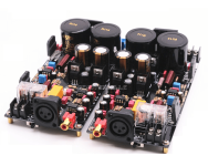
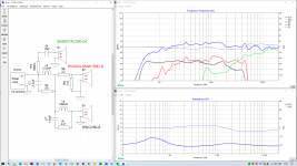
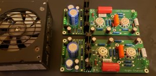
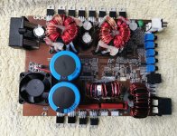
I'm having a go at repairing an Adcom GFA-2535, its a 4 channel amp. 2 channels per board. I have the service manual for it. Amplifier A if working correctly, and sounds pretty good, just needed minor bias adjustment. Not new to DIY, very good with a soldering iron and have a few audio projects done. I thought I'd try understanding the circuit and how it works.

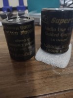
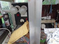
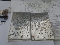
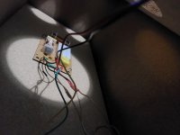
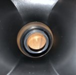
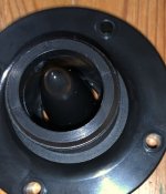
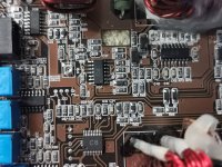
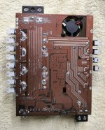
Amplifier B, looked like it had come liquid spilt onto it, very dirty, and first thing I did was clean it up a bit


Just clean water, toothbrush, qtips and blew off excess water


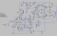
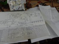
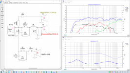
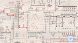
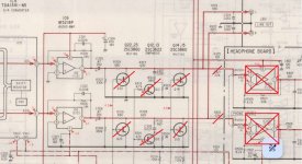
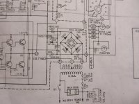
Here's the schematic of the one half of the board, I've highlighted the components that tested faulty from my basic understanding


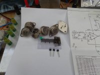
Started diagnosing what was wrong and I've found the following:

1. Both fuses F601 and F602 blown
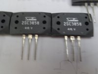
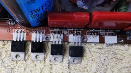
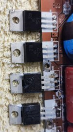
2. Q625 = 2SA1507 - Short between Collector and Emitter, no short between Collector and Base
3. Q633 = 2SB817D - Short between Base, Collector and Emitter
4. Q629 = 2SB817D - Short between Base, Collector and Emitter
6. D607 = DSC30TC - Shorted

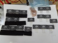
I'm in the process of ordering parts, have some questions
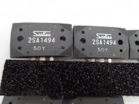
Do I need to replaced the complementary devices for Q625, Q633, Q629 as well?
For D607, should I replace D605 as well if I cant find an exact part match?

For D607, here is the original spec


Mouser has a SR315 in stock. In this position in the circuit, can I use a 1N5822? What does D607 / D605 do?


Any guesses as to what else upstream could be blown based on the info here, would like to get all the parts in one order if possible.

Thanks in advance, looking forward to reviving this board. Have an oscilloscope and function generator to help with troubleshooting after new parts are installed. Looking at getting a transistor tester from Amazon, any recommendations?

Modding a Velleman K4040

I recently purchased a Velleman K4040 amp which I have wanted for quite some time. It was assembled by an engineer a few months ago from a kit that had been in storage for several years and appears to be well built. It came with Electro Harmonix EL34’s. Looking around, it seems that, while being a good amp, it has some shortcomings and can be modded to make it much better. Being a retired electronics tech and an avid audiophile I want to make it the “best it can be” without a complete redesign. It seems there are some mods that can be done such as replacing the 12au7 tubes with 12ax7’s, replacing the concertina phase splitter with a schmidt using 12at7’s ( https://www.diyaudio.com/community/...man-k4040-tube-amp-owner.383508/#post-6952838 ), replacing the coupling cap’s with 100nF’s, etc.. I would also like to replace the EL34’s with KT88’s but still operate them in class AB1 ultra-linear ( https://blog.easychipamp.com/2020/12/velleman-k4040-tube-amplifier.html ), unlike the Velleman K8010’s KT88 bias of 75ma. I must thank Baudouin0, alexcp, ironradio, arcorob, & others for their excellent posts on the subject. This leaves some questions………. In their K8010, Velleman chose to use 47 ohm cathode resistors for their K88’s while the K4040 uses 10 ohm and ironradio chose to use 6.7 ohm with his KT88 mod. I think I understand why to use 6.7’s if you want to bias for 60ma and use the led indicator as is. Is there an optimum cathode resistor value if a person wanted to adjust bias using a meter and not use the led indicator? Also the screen feed resistor value is something I don’t understand. Velleman uses 180 ohm in the 4040 but I’ve seen recommendations of 480, 800 and 1K. Is there an “optimum” value & does it depend on whether the output tubes are EL34’s, 6L6’s or KT88’s? What would be best for KT88’s? Also I noticed that Velleman chose to use DC for the heater of the 12AU7 in the 8010. Why did they do this? Any help or suggestions would be very much appreciated.

https://www.diyaudio.com/community/attachments/manual_k4040-pdf.1028988/

https://www.velleman.eu/downloads/0/manual_k8010.pdf

2.5 way floor standing speaker project

Hi everyone, I'm finalizing my new project and I wold like to have your opinion about the crossover.
The main idea in that project was to build high sensitive 2.5 way speaker with simple crossover (as much as possible). So the driver was chosen to match as much as possible with the idea and of course on reasonable price.
So the speaker is already served by crossover V01 from the picture and sound really good. The main concern in that configuration is the low resistance over 10kHz.
So I make some changes in V02 and I wold like your opinion about two of them.
Thank you in advance 🙂

Attachments

  • 2.5TL_v01.png
    2.5TL_v01.png
    60.2 KB · Views: 145
  • 2.5TL_v02.png
    2.5TL_v02.png
    57.4 KB · Views: 146
  • Like
Reactions: AllenB

Audio Precision AN-1A/1B

Does anyone here used S1 or S2 with the last version of AN-1, CD player tests (downloadable from AP server) in addition with the CBS CD-1 Standard Test Disk?
The CBS20_S1.apb and also the CBS20_S2.apb seem to be buggy. I asked AP, but these Analyzers are no longer under support. It is NOT a hardware problem, but definitely a Problem with these procedures. I was able to fix a little error in the S2 version (Analyzer autorange off), but the main problem is still there. Bad calculation of the delta value.

I know that this is something really special, and i have little hope. Maybe someone can offer me the classic AN-1 for S1.exe ?

regards
Bert

Converting Yamaha CDX-630E CD player to a DAC

Hi All,

I have a Yamaha CDX-630E CD player (Based on Sony CDP-207ESD CD player) which I would like to "convert" it so I can use it as a Dac.
My plan is to connect an input board (DIR9001 based) directly to the TDA1541A chip or to the digital filter if possible after disabling the CD function.
I have a few questions and I'll appreciate your assistance:

1. The DIR9001 input board has I2S output (MCLK, BCLK, LRCK, DATA), assuming I wish to use the digital filter can the I2S be connected directly to the IC4 ? where do I need to connect the MCLK output in the IC4 chip?

2. I noticed that in this Yamaha CD player there are 1K resistors before the Dac inputs, in other CD players the resistors values vary(some use 100r some use 390r), what is the effect of using 1K resistor in comparison to a lower value resistors?

3. I noticed that in the CD player's output stage there is not low pass filter, just an I/U conversion stage, isn't it an issue?

4. My plan is to replace C325/C326 electrolytics (which is part of the output's high pass filtering) with PP or other type of non electrolytic caps, if my calculations are correct then the 47uF C325 and 330K R307 form a very low high pass filtering of 0.01hz -3db, is that really necessary ? can I replace the 47uF cap with lets say a 3uF cap?

5. What is the purpose of R319, R327, R309 ? are they necessary or should I bypass them?


Thanks in advance.

Attachments

  • Dac input.jpg
    Dac input.jpg
    326.1 KB · Views: 169
  • Output stage update.jpg
    Output stage update.jpg
    280.8 KB · Views: 152

Optimizing the Bass Response of an old reconstructed 1984 pair of speakers with new drivers & crossover

Hello everyone and i wish you a happy new year!

I have a pair of no name 1984 speakers that have 2 x 4ohm Tweeters & 2 x 4ohm 8 inch woofers and the cabinet internal size is around 62 litres.

These speakers where my father's and hold sentimental value to me so i thought i would fix/upgrade them by replacing the fried tweeters and the torn woofer cones.

So i kept the original box but i bought new drivers and a crossover and built a bass reflex port (they where sealed).

So what i did was :
- Replace the tweeters with new ones => Bullet type 4ohms each 3khz-20khz connected in series
- Replace the 2 x 8 inch woofers with:
--1 mid woofer 4ohm 60hz-5khz
--1 sub woofer 4ohm 32hz-150hz
  • Added a bass reflex port with 7cm diameter and 60cm in length to tune it to 30hz according to the sub woofer's thiele small parameters and internal box size (used win ISD)
  • Added insulation inside the box (there was none)
  • Added a two-way crossover with a crossover point at 5khz @ 8 ohms 2nd order, 12db/octave ( the speaker had no crossover just a single capacitor previously)
  • I broke the subs in for 4 hours in free air by playing a sweep of 25-hz-100hz in a low to moderate volume level to loosen the suspension

My concerns:
  • Since the sub & mid woofer are in series to present an 8ohm nominal load the sub will be getting more frequencies than necessary.
  • That could potentially cause distortion and the system is not as efficient as it should and lose performance.
  • I'm also concerned about phase issues as the mid woofer and subwoofer have an overlap across 60hz-150hz (according to what the manufacturer states in each of the drivers specs).

While Listening to them:
  • Even though the bass is deep and present i have to crank the eq to +6db to get a good enough bass response out of them especially in low volumes
  • When using a single powered 8 inch subwoofer the performance of the powered sub is MUCH better than my speakers at all volume levels

My questions:


  • Why is the single powered sub has such a drastic difference in bass performace against my 2 x 8 inch passive subs? In order to get the passive subs to perform the same i need a boost of at least 6db on the eq/tone control to get the same performance which is really good by the way so it is not neccesarly a speaker problem but an amp problem?
  • If i made a custom 3 way crossover for each of the drivers in the speaker would that dramatically increase the overall performance or would it be a slight increase in performace?
  • If i did make a custom 3 way crossover i would strain the amplifier as i would present a 4ohm load instead of an 8ohm load
  • Should i remove the passive subs from the speaker boxes and use 2 identical midwoofers instead? And rely on the active sub for the bass only?


Note: My living room is huge; it's around 65 square meters and 4.5 meters tall. To get best result i used the powered sub in conjuction with the passive subs integrated in the towers. I have a digital eq on my phone which i set up to boost +6db with a center frequency of 60hz and a wide q while i lowered the volume the powered sub plays to 1/4 so that it complements the passive subs. That way i get rich deep bass at low and high volumes without too much stress. I never listen to particularly high volume levels but i do listen to bass heavy music such as hip hop and house music.

Speaker pics attached, Looking forward to your expertise and suggestions!

Attachments

  • 20231108_181217.jpg
    20231108_181217.jpg
    86.4 KB · Views: 64
  • 20231230_102411.jpg
    20231230_102411.jpg
    316.3 KB · Views: 60
  • 20231230_102406.jpg
    20231230_102406.jpg
    236.7 KB · Views: 61
  • 20231118_144042.jpg
    20231118_144042.jpg
    142.8 KB · Views: 63

Yamaha CR-420 Service Manual

Hello,

I'm restoring a Yamaha CR-420 unit. I was able to track down PDFs of the User's Manual and Schematic, but cannot find a PDF of the Service Manual. I see it's available at hifiengine but they are not taking new registrations. I would offer to throw some $$ their way in the form of a donation but I can't even find an email address on their site. If someone can share this PDF I would be eternally grateful.

Thank you.

Dipole Line array with GRS Slim 8" and Visaton WS25e

After Christmas I hope to start building a set of 2 way open baffle Line arrays, based on 12x Slim 8” from GRS GRS PT6816-8 8" Planar Slim Tweeter 8 Ohm and 9x WS25e woofers from Visaton (cheap driver and I got nice results from them in previous builds).

All drivers will be used nude, I will use 2.5mm stranded wire for hanging them from the ceiling (and power the drivers). The crossover point will be somewhere around 750Hz (unfortunately cannot get lower as the Slims start distorting). With time I may add some sort of subwoofer to the system.

I have been thinking how to arrange the arrays to each other to obtain the “best results”. One consideration is the gap (distance) between the woofer and slim array: higher value would probably be better to let either array operate without influence from the others array “baffle”, OTOH the distance should be low thinking about the “ideally less than ¼ of wavelength” distance between drivers.

The other consideration is alignment of the acoustic output, for time (or phase) alignment of the drivers. It can be expected that, seen from the top, the slims will have to be shifted back for best time alignment. But that would put the woofers in the way of the dipole radiation of the slims, which I do not think is a good idea. So maybe mount the slims aligned with the front of the woofers and add the delay in the crossover, like shown in the picture?

I will have a wooden plate attached to the ceiling and will be able to shift the drivers in an area of about 360 (wide) x 200mm (deep), so there will be some experimenting on its way. Still, very curious about your opinions!

Many thanks, Erik

Attachments

  • DispositionWooferAndSlims.png
    DispositionWooferAndSlims.png
    43.6 KB · Views: 1,115

ARCAM FMJ CD23 - High noise floor

Hi all,

I'm reaching out to the community to discuss and compare others' experience on the ARCAM FMJ CD23 (not CD23T) noise floor.
I bought it a year ago and upon having the laser replaced I used to listen to it from time to time. Recently, however, I've discovered a surprisingly high noise that you can distinguish by wearing headphones and cranking up volume before switching on the player.
Upon the player switch is pressed, for a few seconds the noise level remains as if the player was still off, but as soon as you hear the output relè click activating the channels' output, a subtle but distinguishable noise pops up. I'm not talking about any music reproduction defect but of the noise hearable by simply switching on the unit.
A comment on a slightly higher noise-floor was reported by John Atkinson when he recapped device's measurements in his article, but before digging down to find a potential electrical cause in the DAC board which, being multilayer, is not easy to fix I would appreciate if any other CD23 owner can share their experiences

Cheers, Riccardo

  • Article Article
Transformer Dot Notation

Attachments

  • transformer_dot_notation_M-1-1-e1694232639337-qc52zbnn4r32o5h6sipteshu6p7y9otomw2ziatatq.png
    transformer_dot_notation_M-1-1-e1694232639337-qc52zbnn4r32o5h6sipteshu6p7y9otomw2ziatatq.png
    6.7 KB · Views: 104

Open Baffle crossover help

Hello,

Before I post my question below, let me provide a little background. I am in the process of building my first speaker project. This will be an active crossover and multi amp driven system. Room area around 20×18. Below is a brief plan. Please excuse me if my, question is dumb. I dont posses an engineering background.

H-frame open baffle Bass section: 2×15 inch sb audience bianco OB drivers. This will cover between 20hz to anywhere between 120 to 200hz. One of the woofers will be restricted to 60hz the other will.cover the entire bass frequency bandwidth as describwd above.

Mid bass/lower midrange: 1×12 inch SB Audience bianco OB woofer. This will take it from whatever I decide to terminals the bass upper limit all the way to around 750-850 hz.

Midrange: Either a Fullrange Dayton Audio/Fostex or possible the SB Audience 6 inch Nero. The plan is to cover from the mid-bass cutoff to around 4-5KHz.

Tweeter: Planar magnetic to cover upto 20KHz.

I will be managing crossovers via a Peavey VSX 48e balanced 8 channel speaker management system.

Question: For the bass section, would it be possible to parallel the 2 15 inch woofers while adding an 80 Hz low pass in series with one of the woofers? I would like to keep the system to a 4 way hence need to parallel the bass section. Or would it make more sense, to use indepenent channels to drive each woofer while combining the mid and tweeter to a single channel via a high pass in series with the tweeter.

Thank you for your time.

Nik.

For Sale Bliesma, Scanspeak, Dayton

(3) Bliesma T25B-6. New in the box. Matched pair $550 $500 shipped, single $250 shipped.SOLD

(1) Scanspeak 2104/7120 3/4" Revelator tweeter. New, only used for measurements. $125

(2) Dayton AMT2-4. New in the box. $110

(2) Dayton ES180TiA. New in the box, one was removed for measurements in a project that did not move forward. Awesome motor and low distortion. $200 SOLD

All prices include shipping. Paypal only. CONUS only.
  • Like
Reactions: Arez

Why is my ONKYO TX-SR705 40 watts in standby

Hi All,
While messing around with some power monitoring receptacles / plugs / switches I noticed that my ONKYO tx-sr705 consumes 40watts in standby with zone 2 turned off. This got me curious as to why? I tested some other units and found that none in my test set used so much power in standby.
QUESTION: Is it the serial control, something specific to this model or a logic error that turns of the "source" of Zone 2 but leaves the transistors hot?

ONKYO tx-sr705 Transistor / RS232 / HDMI / 2 Zone 40W
ONKYO tx-sr700 Transistor / 2 Zone <2W
Pioneer vsx-1015tx Transistor <2W
ONKYO ht-r590 Chip / HDMI <2W
Yamaha rx-v657 Transistor / 2 Zone <2W
JVC rx-552v Transistor <2W
ONKYO tx-sr601 Transistor / 2 Zone <2W
DENON avr-1802 Transistor <2W


Jeremy

Refurbishing PSB Image 6Ts - sanity check!

I've recently come into possession of a pair of PSB Image 6T speakers, which I'd like to refurbish and give to a friend as a gift. You can see their layout here (one tweeter, three midrange/woofers per enclosure).

All 6 of the original midrange/woofer drivers have perished (either blown or rotten), and I've acquired replacements in the form of 8 ohm Jaycar 6.5" midrange/woofers. I'm also going to replace the tweeters with 4 ohm Tymphany units (drop-in replacements) unless I can find 8 ohm versions of the same.

My issue is that the original crossover (originally 2500Hz) is now no longer likely to be viable, given the new driver impedances. So, replacing the drivers means replacing the crossover also.

1. I won't have time to build the crossover myself, and was thinking about either this unit, which has adjustable attenuation, or this unit which crosses at 2500Hz (which might sound better). I'm not sure which one to choose.

2. I expect that the speaker will be a 2-way setup, with one circuit for the tweeter and one circuit for the 3 midrange/woofer drivers. Should I connect the woofers in parallel? Or Series-parallel?

As you can tell, I'm a noob. Any advice at all would be very helpful!

Dynaco S70 Power supply wire help

The replacement power supply wires are different colors then then my dynaco s70 Power supplies are both pa060
What i can do is measure the voltage of the replacement power supply and label them .
If i had a actual picture where these wires soldered too i could connect it back in easily . Picture should have the voltages . All the old factory wires are still connected .
I cant tell you the factory wire colors faded I am not sure what year my amp is its old possibly 1960s Bought i use
If you have this please share .

Considering AMT tweeter - Advice or experience?

I've never run AMT tweeters, but I've read some positive reviews. It seems like they might excel in reproducing 16k-20k+.

But if that's true, I wonder why they're not more popular. These are the ones I'm considering.

At any rate, do you have any experience with AMT tweeters? Any positives/negatives? Would you recommend them? Anything to know before going down that road?

Any advice or experience would be appreciated. Thanks!

PC PSU to power tube preamp boards?

Bought these nicely done tube preamp boards from eBay and would like to know if a PC PSU can be configured to power them.

"This board is mono Mirror Design. the circuit is base on the famous Conrad-johnson preamp.The sound is very excellent."


Each board works voltage: 0-AC220V (about 25mA) 0-AC7V (6.3V-9V are all ok. about 1.2A)
ECC83 Tube preamp kit

Attachments

  • 20231224_094223.jpg
    20231224_094223.jpg
    259.2 KB · Views: 110
  • 7079p9gezib41.jpg
    7079p9gezib41.jpg
    381.4 KB · Views: 96

Cheap compression tweeter tuning

I got some really cheap compression drivers to play with. I can see some flaws in the design and I will try to improve them. Level 1 will be filling the phase plug with hot melt glue and use another horn attachment, since the existing one is plain bad - with a step at the throat and a long section without any expansion.

The air gap is filled with ferrofluid. Is it worth trying to remove it and is that even possible?

Level 2 will be improved 3D printed phase plug and level 3 completely new front - maybe with an integrated horn or K-Tube.

Attachments

  • 0230E95A-7A6D-4C75-94D9-42B654736167.jpeg
    0230E95A-7A6D-4C75-94D9-42B654736167.jpeg
    97.8 KB · Views: 390
  • 55D0ADE7-CFA0-4BA1-847D-E2FA4F2AEB39.jpeg
    55D0ADE7-CFA0-4BA1-847D-E2FA4F2AEB39.jpeg
    319 KB · Views: 365
  • 0ECE011E-08FC-4C19-9107-5309ED785121.jpeg
    0ECE011E-08FC-4C19-9107-5309ED785121.jpeg
    68.2 KB · Views: 387
  • 9A1471B3-83A2-4C08-B9F0-E3299256E0DE.jpeg
    9A1471B3-83A2-4C08-B9F0-E3299256E0DE.jpeg
    96.4 KB · Views: 383

Crimson Elektrik 530 Amps with hum - repair / restauration?

Hi there everybody!


I have a pair of vintage Crimson Elektrik 530 mono power amps.

They worked and sounded pretty good. However, they started humming some time ago, and its getting stronger over time, in particular on one of both. Otherwise they still work well, but given that I have high-DB-speakers, the humming got really disturbing.

I have no clue in electronics... but I am ready to exchanging parts, soldering on the board, etc. So I just would have to know, what to do...

More precisly, my question to you guys would be:
- What should be done to troubleshoot that humming?
- Are there parts that should be exchanged anyways for their age? What parts (brand/type) would you recommend for the replacement?
- Might I start with re-soldering together the old parts in order to improve contacts?
- Honestly, would you think, taht it's worth the time and cost, or should I rather look out for something new? Given that soldering and parts shopping is not exactly my hobby. but I do it if this gets me back my nice amps.
- And if I already start soldering... are there upgrades that would make sense?

Below you find the pictures of the board and parts inside the amps...

Thanks INDEED!!! for any useful help and advise!!!

Best regards, Urs


Link to pics: Crimson 530 — ImgBB

Quantum Electronics

Hi All,
anyone out there have any info on or time spent with, the Quantum Electronics series of Amps and Pre Amps? I used to have a set of the 102 and Mono power amps about 40 years ago, but they're long gone - I have just picked up a 207DA.
Specifically information on the 102 if possible, but anything on these amps would be of interest.
Many Thanks
Joe

Setting Bias via balancing speaker output voltage.......

I have been pondering balancing speaker output by setting the bias so the speaker outputs voltages are equal,
rather than the bias voltages being equal while monitoring the bias voltages for longevity sake of the output transistors,
I can do this with my sound generator and oscilloscope.
Equal input to both channels while looking at the voltages of both outputs.
Seems like a a great way to compensate for ,minute L-R circuit differences.

Spendor SP1/2e Replacement Woofer Ideas 🔈

Hello all.

I own a pair of Spendor SP 1/2e's that I am interested in restoring and/or upgrading.

I have purchased replacement tweeters and mid range drivers (new in box scanspeak).

I now need to find replacement woofers for the cabinets. The current drivers are Spendor SD-08-A (no. 19873). Picture attached.

I am having a hell of a time locating a pair. I would like to go with unused condition obviously.

Any ideas for either an upgrade or a source for the original?

Screenshot 2023-11-22 at 11.40.23 AM.png

Help with preamp circuit

I purchased this 2.1 preamp from Amazon to incorporate into a project I'm working on. I specifically need it to perform low pass filtering to send signal to a mono tpa3116 board. However as all other preamps Ive tried it doesn't filter out enough of the voices. Its supposed to be a 12db slope with adjustable frequency from somewhere around 20hz-200hz however even at the lowest setting it still allows allot of voices through. Is there anyway I can adjust/fix this board? I am good at soldering and have already played with the feedback loop of the stereo gain but can't figure out the bass circuit at all!

Circuit diagram

PCB

Would removing the potentiometer for the frequency adjustment and just fixing the LPF at 60-80hz at 12db slope be viable?

Best 18” Driver for midbass

Morning all! Happy New Year.

Quick question- I’ve ordered 4 drivers back in September from Acoustic Elegance and have no idea when they might ship. Super excited to get them, but frustrating on the lack of a simple email response etc.

That said, I know John is a genius and does amazing work so I’m just hanging out until they show up one day.

In the mean time- I’m building a 2 way speaker with an Oris 250 Horn on top using the Celestion AxI2050 compression driver.

Already have had that up and running for months.

Finally got my 18” mid bass custom enclosures in, and now I’m desperate to find another driver to at least set up in the mean time.

Which other 18” drivers could you recommend- above 96db sensitivity that will play CLEAN up to about 400hz?

And by clean I mean with the ability to be used in a 2 way config?

Thanks in advance!

What the hell is Class A3?

Does any one know what Class A3 is ? Is it a modified "linear Class C" operation, or something crazy like that ?

I have been into electronics for decades and never heard of this Class, despite being an avid researcher on Audio design. I stumbled across it when looking at Electraprint output transformers as they make single ended Class A3 output transformers. The circuits Electraprint presents as A3, to me look like standard Class A1 or A2 designs - nothing special.

What advantages does it have over classical SE Class A designs ? How does it sound to the ear ? Does it have lower distortion, more power, better bandwidth; etc ? What drive requirements does A3 need ?

If my suspicions are right - this looks like one of those "new American inventions", where they change a part or two on on old well known design ( ie: re-invent the wheel ) and then claim they have invented something new; then suddenly rush out before anyone knows about it and get a patent put on it with the rights to sell it for a licence fee?
I say this because Electraprint won't allow you to commercially use their Class A3 tube designs without getting a licence from them. So my apologies for sounding sarcastic on these so called new-fangled inventions - as the electronics industry wreeks of such.

I also did a Google search and nothing came up that even discussed its operation.

Very nice Burro open baffles for free in SF Bay Area (No Drivers!)

I have the plywood assembled with hinges and holes. This is good plywood: 3/4" (or close), no voids, masonite on one side.

I have no idea where the drivers went: please be sure you understand that the baffles don't include the drivers.

I can't imagine shipping these, but if you're in the SF Bay Area you can have them for free if you pick them up in Berkeley.

If you want to express thanks, you can donate a small amount to the nonprofit of your choice, but not required.

60 cycle hum in my vintage Sherwood receiver

I recently reconditoned my Sherwood 7110B receiver from the 1970s with all new aluminum electrolytic capacitors. It now has a low-level 60 cycle (US mains) hum that remains at the same low level at any control setting. The hum is barely noticeable when music plays but is quite annoying when no signal is present. I did not notice the hum when I last tested the receiver with the original capacitors but I can not positively say that it was not present at that time. The receiver is rated for use with 4 ohm speakers and I use it with my 4 ohm monitors.

I replaced the old capacitors with new ones of the same capacitance values and upgraded the temperature ratings when possible. I checked the cap values before installation with a capacitance meter of known accuracy and double-checked the polarity orientation before and after installation. I checked for cold solder joints, bad circuit board traces, loose wires and short circuits, and cleaned the boards with isopropyl alcohol, and still have the hum.

The power supply is a simple design (see attached photo), with rectifiers, filter caps, and Zener diode regulation. It seems to me that the receiver should not hum, but it does. Can anyone help?

Attachments

  • IMG_0043.jpg
    IMG_0043.jpg
    980.4 KB · Views: 180

Can mute/soft start be added to SONICS 800x amplifier?

Hey guys.. new here.

I am running two sonics 800x amplifiers to power the woofer section of my Bryston Model T speakers. These amps are similar to a Bryston 7B NRB with some different circuitry (were used for imax theatres).

Anyhow they work great when powered up - lots of power. My concern is that when powering up/shutting down, they present a loud thump through the woofers. Is it easily possible to add a muting/soft start type circuit to these in order to a) protect my speakers and b) get rid of the noise?

Thanks!

In-ceiling speakers: box worth it?

Building a home theater, including a "drywall" ceiling. I've decided to mount the speakers in the ceiling. They are going to be small ones, perhaps 4" FaitalPro 4FE32.
And I started wondering. Can I simply install them and add some soft material behind, making it an "infinitely large box", or should I do (vented) boxes?
Boxes would require quite a bit of work, but would it be worth it? Is there any benefit, sound quality-wise?

Edit: dang, turns out I should be celebrating 20 years on diyaudio 😵

Jolida 502BRC bias issue questions

Had this amp serviced twice and still having issues. First time I had a red-plate tube and the amp was shutting down. Was told there were a few bad solder joints and I needed a new set of tubes. Next I Had some hum on one channel, and the port for getting the bias reading with a meter was not giving any voltage readings. Brought it back. pretty sure there was a loose molex plug for that feature- but I’m not sure what else he did

To clarify- the hum that I’m describing is coming out of the speaker. No idea of the frequency, but I’m guessing it’s 60hz

Anyway-If you follow the manual on setting bias for this amp, you turn the gain pots all the way down, then turn up the voltage to 500mv (2 x 6550/channel) for each tube

When you first start to turn up one of the pots, there is some audible hum, which I’m assuming is a balance issue between the 2 push-pull tubes, until you turn up the other pot to 500mv as well.

This is fine for the right channel.

Now on the left channel, the one with the “hum” issue, one of the gain pots will not zero out. In fact, when I turn it all the way down, it doesn’t go below 300mv..

So that pot I can adjust to 500mv

But what happens it when I try to adjust the other tube pot to raise the voltage, the hum gets louder and louder beyond 250mv.

So basically, with pots all the way down it’s
L( 0v, 300mv) R( 0v, 0v)

With gains set, and least amount of noise it’s

L(250mv, 500mv) R (500mv, 500mv)

Could this be from a bad potentiometer?

Thanks

IMG_1029.gif

Yamaha transformer question

Hi all. Can someone please advise me regarding re-using a Yamaha transformer stripped from an RX-V577? There are 2 wires that originally connected to the power switch, the yellow ones in the pic. Can I just connect the primary directly, and then measure the secondary voltages, or will the transformer not switch on, because the soft power switch that the yellow cable led to is not going to be used? Sorry if this is a lame question.

Attachments

  • 20240101_141844.jpg
    20240101_141844.jpg
    314.3 KB · Views: 86

Fixed bias applied to the cathode

Hello everyone,

I am planning to build the circuit below, but I'd like to convert the gain stage to fixed bias. The autobias is currently 20mA, with a 100 Ohm cathode resistor, which corresponds to -2V between grid an cathode.

Since I don't want any capacitors on the signal path, my only possibility to apply the bias is to elevate the cathode.

To achieve that, my idea is:
Reduce the value of the cathode resistor to 10 Ohm (Instead of 100 Ohm).
Connect a +2V ultra-low-noise regulated PSU to the the cathode.

In theory, in that way, the current from the cathode is absorbed by the regulated PSU (assuming it can work on a negative current) and the cathode voltage will be imposed by the regulated PSU only. In theory.
Is there anything I am not considering?

Alternatively, I can add a 1:1 input transformer and apply the DC bias to the secondary of the transformer.

1703759222834.png

Benchmark DAC 1 USB issue

Good evening and happy New year! May the new year bring joy and health to you all!
For a few years now I have had an upgraded 1 usb dac which is my sole source through the 2 cd transports I use. I use its xlr outputs to the rca of my preamplifier in the way that the benchmark advises, i.e. pin 3 should remain floating. In the last months after hours of use I lose the high frequencies from my right channel or I should say better that there is a shift of the stereo image to the left, which can be fixed temporarily by playing with the back gain mode selector switch. One would say that this is the issue on the dac, but today I tried to test the rca outputs of it and not the xlr ones. I noticed that the temperature of the dac decreased noticeably, but also of my preamplifier. The sound was obviously degraded since the dac is not famous for its sound on its rca outputs. The problem also exists in the rca outputs and is even more noticeable there. I'm confused about the patch but it's playing fine... but what I'm worried about the most is the temperature thing.. should I put it in the closet and get something more modern and if so what??

Celestion G12 Greenback

Hi I'm looking for some speakers to replace the stock 12's in my 4x12 cab. I've seen some celestion g12 v types which look good and reasonably priced at £85 from a respected shop.
I've also seen some new celestion g12 greenbacks on ebay for about £80 each and discounts for multiple speakers which seems pretty good to me but I'm concerned it's too good? Thoughts please are there fakes? Returns?factory seconds? Going around.Things to be aware of?
Thanks

Amplifier selection for 18” subwoofer project

I am building a Marty’s based subwoofer using an Ultimax 18” subwoofer.

I need some help/opinion on what amp to pair it with.

Currently looking at (used)
Behringer NX3000d
Crown XTi 2000
Crown XLs 2000

I hear that the behringers have quality issues which is leading me towards the crown. Afak the XLs is class D and the XTi is class A/B. I will be using the amp bridged at 4ohms and only driving the single speaker.
The XLs has direct RCA and the XTi needs an RCA to XLR cable (not a big deal).

Anyhow. Experts. What do you think?

EDS3000.1FD-E0 class D full range amplifier

good evening everyone...the above amplifier is stuck to clip led indicator....one output fet was short....it has 4...
anybody knows the component values?c4?c8?c3?c5?the output and power supply?h1?h6?

Attachments

  • IMG-d3b2bb42d43dd5a24387cec041298f35-V.jpg
    IMG-d3b2bb42d43dd5a24387cec041298f35-V.jpg
    235.9 KB · Views: 208
  • IMG-fbc5cd72fe7a1164e779e790c9f18b49-V.jpg
    IMG-fbc5cd72fe7a1164e779e790c9f18b49-V.jpg
    227.5 KB · Views: 197
  • IMG-b436b4a92602457300e5165f70d390c1-V.jpg
    IMG-b436b4a92602457300e5165f70d390c1-V.jpg
    196.6 KB · Views: 181
  • IMG-e0e4f714b6bda60a3a724639c345503a-V.jpg
    IMG-e0e4f714b6bda60a3a724639c345503a-V.jpg
    210.8 KB · Views: 183
  • IMG-deeced992e3253de2f225d1a7ddc423f-V.jpg
    IMG-deeced992e3253de2f225d1a7ddc423f-V.jpg
    229 KB · Views: 177
  • IMG-5fe2db70263796bb04b2868384c3dc45-V.jpg
    IMG-5fe2db70263796bb04b2868384c3dc45-V.jpg
    232.1 KB · Views: 196
  • IMG-741cacbc154d38421e3c52f0284f1e9d-V.jpg
    IMG-741cacbc154d38421e3c52f0284f1e9d-V.jpg
    170.8 KB · Views: 180
  • IMG-8dcd912576ee27a93580f1b3b7c31fd8-V.jpg
    IMG-8dcd912576ee27a93580f1b3b7c31fd8-V.jpg
    229 KB · Views: 197

amplifiers for 8 - 8ohm speaker

I'm working on building a system that will consist 8 8ohm speakers for a sound installation in a small/medium art gallery.

I will play 8 different audio files from my 8 output audio interface.

I was thinking to use either those 30W speakers to those 8W speakers
is 8W speaker (or less) is enough for installation? (the sound is not need to be too loud for that application)

Which mono amplifier board is recommended?
How is the TDA2050 board for the mission? will it be needed to add fan for the 8 amp box I will build? or the heatsink is enough?

what shall I consider in choosing a board?

Thanks

Speaker wire signal to line level

I have a Samsung TV with only an optical output for audio and have tried the optical to RCA converters but would like to not have all the extra wires to deal with. I tried taking signal from the TV's speakers using a simple voltage divider to a RCA jack I installed in the TV's rear panel and it worked kinda.. I'm getting noise that kind of sounds like a ground loop mixed with interference. I figured my next step would be to try some ground loop isolation transformers or swap the 2 prong TV plug for a 3 prong cord and attach the ground to the TV's circuit board. I have a Yamaha AVR that I did that to and it solved a bad ground loop I got when connecting an external amplifier via the RCA audio out jack on the AVR. Does this sound feasible or am I wasting my time? The biggest reason I want this to work is so I can control the volume using the remote.

Redisplay of Acoustic Sound Fields in AKABAK 3

Hi All
I am very new to AKABAK 3, although I have used AKABAK 2.1 for a while. My question is, after I have calculated and displayed the sound fields generated from the AKABAK 3 model, closed the model and saved it. How do I get AKABAK 3 to redisplay the sound field data without recalculating (takes hours)? I see there is an *.AKBPE file that I have tried to reload, but no responses show up.
I have the Student Version.

Thanks for your help.
-bw-

Great audiophile recordings/albums

Recently, doing evaluation on componenets and systems, I started listening to somewhat more "advanced" and audiophile recordings😉

I'd like to share here what seems to be sounding good, is well recorded and presents quality, interesting audiophile material. I'm always on a lookout for that type of recordings, so I hope this thread will continue and will be updated on regular basis, providing a source of inspiration on what to look for next time you visit your local records store.

So here's the first run. Most of you are probably familiar with Jacinta's album. Patricia Barber's, Companion, is also very good live recording. Burmester CD III sampler is my all time favourite and it contains all kind of different material, from classical, jazz to more contemporary stlyles and even Chinese percussion track. My recent buy, Holly Cole's Temptation is great adaptation of Tom Waits songs.

Attachments

  • rec1.jpg
    rec1.jpg
    47.6 KB · Views: 4,347

Focal 7K0DBL in Carat Megane detached dust cap. Reattach?

I just bought a pair of JM Lab Focal Megane Carat. They sounded amazing when I bought them, but of course immediately one woofer started rattling. I very gently pushed the cone to check for voicecoil rubbing and the dust cap just peeled away. That stopped the rattling but now there's no dust cap. I guess the dust cap was just flapping against the cone causing the rattle. Hopefully that's all it was.

Anyway. I don't know what adhesive I should use to re-attach it, or if I should just replace the woofer.

It's been a while since I've done any DIY or made any audio purchases, so I'm "under moderation" and I can't contact or reply to this older listing: https://www.diyaudio.com/community/...ge-pair-dual-voice-coil-7-inch-nh-usa.390049/

Any advice is welcome; Happy New Year.

Tecron TEF-10 TDS analyzer- it's still alive!

I've been thinkng of setting up a rig to do some basic headphone measurements. It occured to me that I have a TEF-10 analyzer sitting in the basement, that I bought new in 1983 and mothballed in 1989 (after upgrading to it's big brother TEF12+). After locating the box of 5.25" floppies it uses , I decided to boot it up and give it a spin. To my great surprise, everything works fine! All of the 33- to 38-yo floppies are also good. This defies everything I've read about floppy data retention.

Thought I'd post some eye candy for those that are unfamiliar with this amazing machine in its day.

The plots are measurements made in 1988. One of them is the anechoic mag and phase response of a polycone tweeter on a test baffle. At 3dB/div, not bad for a cheap driver. The time offset isn't quite dialed in for accurate phase representation - a couple uS off still - but it was close enuf to see that it was minimum phase. The other plot is a 3D "waterfall" display of an unidentified speaker system.

The only thing that makes me think twice about using this system today is the floppy drives.

Attachments

  • Bootscr.jpg
    Bootscr.jpg
    171.4 KB · Views: 311
  • front.jpg
    front.jpg
    293.3 KB · Views: 378
  • Mahpha.jpg
    Mahpha.jpg
    227.1 KB · Views: 311
  • rear.jpg
    rear.jpg
    180.1 KB · Views: 352
  • 3Dmag.jpg
    3Dmag.jpg
    366.4 KB · Views: 297
  • side.jpg
    side.jpg
    133.1 KB · Views: 271

Do you measure how loud you listen?

The first time I did I was pretty surprised at how low the numbers turned out to be.

I typically listen at around 70 dB, and rarely - if ever - see peaks much higher than 90 dB. I don't have a setup to let me measure the acoustic levels, so I just use a scope and assume the phone specs are close enough to get me in the right ballpark. No claim of precision here.

With my 32 Ohm, 100 dB/mW phones the raw measurements show only a handful of mV RMS with peaks below 100 mV (and usually below 50 mV).

Do you ever measure your listening level? If so, what do you find?

Just curious

jason
  • Like
Reactions: knarfor

SR5008 Thermal protection fix

My Marantz SR5008 receiver was shutting down due to a thermal protection error. It took me a long time to properly diagnose this failure, because it was sometimes shutting down after only a few seconds, sometimes after a couple of minutes, and sometimes it was functioning properly for a few days.

You can manually bypass the protection circuitry by pressing power+display+status+sound mode. 'Protection pass' is displayed, and everything was working fine. However, this is not a solution, so I tried to figure what the problem was by disassembling the amplifier-radiator module (7ch amplifier).

I measured the PTC resistors, and there was some variation, but I was not sure if replacing them would solve the errors. After reading another post on this forum about a similar amplifier (denon x1200w), I decided to disable the thermal protection for ever.

See attachment where to break the lines on the PCB of the amplifier module. Caution: you have to break/stop lines on both sides, so you have to desolder the power transistors. Of course, your amplifier is not protected against overheating, so only perform this operation if all other options failed!

After this has been done, no thermal protection errors, and my amplifier has been fixed!! 🙂

If you have any questions please send me a PM.

Attachments

3D printed K-Tube for 2" compression drivers

Working on my multicell horn and reading of some other K threads lead me back to the idea of trying out a K-Tube on my JBL2445. There are 4 models attached - single and dual slot, each in two lengths. The shorter one is around 1/4 of 500 Hz wavelength and the larger one is maximum size for my QQ-S printer. I will start printing today so that they are ready for the big polar measurement race between multicell, 2380 clone and K-Tubes (scheduled for mid October due to work travel🙁 ).

Attachments

2 chokes, are they keepers ?

I have recovered 2 chokes from an old UPS system, with my LCR meter, they measure:
  • choke 1: 2.8 mH, 0.19 Ω DCR, Q=4.87, wire Ø 1.6 mm
  • choke 2: 130 mH, 0.88 Ω DCR, Q=3.37, wire Ø 0.9 mm
I'm into tube amps, where I usually see higher L values in DC filtering. Is there any usage you can see for them, or should I avoid adding them to my cellar stack of heavy metal ?

DAC Help!

Hi, I want to build my first DAC , I don't care about performance, just for fun.
I was looking at AK4117 for spdif receiver, and I don't know how to config it, can I by PINS ( switches to select different modes ) or I need a micro controller, processor for that? .
Can it run by itself?. no MCU,
For DAC , CS4360, CS4340, PCM1680,
- Old ic's here. I know. Just wanted to build something for fun if possible.
- Cheers, Bruno.

Attachments

Need help picking a mid-driver (3-way build)

I'm here just to pick a mid its currently between 3 drivers.
first of all this build is using 2x 12in woofers in the bass (Vifa M30wo-15) and a vifa D27 tweeter.

for cost i was just going to get a Peerless SDS-P830657 6½" but i saw some Dayton 8in's that look better on paper then the peerless they are the DS215-8 (paper cone) and DSA215-8 (Aluminium cone)

theses look to have a better off axis responses than the peerless (and i think they look much better and much easier to counter sink)
i would get the paper cone but there out of stock for quite a while so the peerless or dayton 8in

Xover will be about 500hz for the bass and mid to tweeter would be about 2.5 to 3khz

SIDE NOTE
The Vifa M30wo-15 don't have a specs sheet and i cant find on the on web but i did find a close one below VV
(http://www.sea.vg/vifa/M30WO-49-08.pdf)

that spec sheet states that they have a 93dB sensitivity at 1 watt (mine are 4 ohm and the spec sheet is for an 8ohm coil i know) but i am getting a dayton DAT and miniDSP UMIK-1
and i would like to get the mids at the same time as the only place that sells it is over seas and would prefer less shipping hassle.

i also already have these the Vifa M30wo-15 drivers all 4 of them. 1 was damaged and had to dissemble the driver to fix the bad glued coil
they also date to 2001


Any help would be largely appreciated XD.
Projects by fanatics, for fanatics
Get answers and advice for everyone wanting to learn the art of audio.
Join the Community
507,672
Members
7,883,590
Messages

Filter

Forum Statistics

Threads
405,997
Messages
7,883,590
Members
507,672
Latest member
rooomn