Hello everyone,
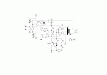
I am planning to build the circuit below, but I'd like to convert the gain stage to fixed bias. The autobias is currently 20mA, with a 100 Ohm cathode resistor, which corresponds to -2V between grid an cathode.
Since I don't want any capacitors on the signal path, my only possibility to apply the bias is to elevate the cathode.
To achieve that, my idea is:
Reduce the value of the cathode resistor to 10 Ohm (Instead of 100 Ohm).
Connect a +2V ultra-low-noise regulated PSU to the the cathode.
In theory, in that way, the current from the cathode is absorbed by the regulated PSU (assuming it can work on a negative current) and the cathode voltage will be imposed by the regulated PSU only. In theory.
Is there anything I am not considering?
Alternatively, I can add a 1:1 input transformer and apply the DC bias to the secondary of the transformer.
Putting a power supply there could open a can of worms. Also, 2.0V is not battery-friendly.
Try a red LED, although 20mA is the typical maximum constant current allowed by generic ones.
Try a red LED, although 20mA is the typical maximum constant current allowed by generic ones.

I'm not sure what you want to do with the 10 ohm.
A normal series-regulated supply can supply current, but barely sink any current, but you could use some sort of 2 V shunt regulator. The simplest implementation would be a Zener diode or an LED, as mentioned by jcalvarez. In either case, you have a semiconductor in the signal path.
A normal series-regulated supply can supply current, but barely sink any current, but you could use some sort of 2 V shunt regulator. The simplest implementation would be a Zener diode or an LED, as mentioned by jcalvarez. In either case, you have a semiconductor in the signal path.
Can the negative supply to the interstage transformer be increased? Would this achieve your goal?
The ac equivalent circuit will show you that each cap on this circuit is in the signal pathSince I don't want any capacitors on the signal path, my only possibility to apply the bias is to elevate the cathode.
Each raw of Vdc has a electrolytic cap (or pp) as last cap and it is in the signal path
Last, you are worry about cap when the inductors and trafo are more complicated???
Walter
The 10 ohm resistor is to guarantee that the 2 volt supply is always sourcing current.I'm not sure what you want to do with the 10 ohm.
Yes, you can as long as the supply is always sourcing current.You can't add a separate voltage supply for bias in the cathode ... it doesn't work , basic electrics .
If I was to do this I would use a 10 ohm or so resistor for the cathode resistor and either feed that about 200 mA through a larger resistor or CCS circuit. The idea is to create a 2 volts fixed bias VOLTAGE on the cathode with only resistive or high impedance (the CCS) connections in parallel. Yes, this is a serious waste of power but it can work.
Yes, this is a serious waste of power but it can work.
One question:
Why to do this?
Walter
You need a constant voltage source like zener.
I once tested the fixed (but adjustable) cathode bias with attached arrangement. There the TL431 is adjustable and drives MJE2955.
I've tried a very similar circuit, and it works great to bias the power section in a 6360/GU-17 PPP amp I've built. To work in this case it must be connected to the negative rail, since there is no headroom if the TL431 is connected to ground. Vref alone for TL431 is 2.5V.
You would only do this to avoid the bypass capacitor on the cathode. Some people still do not like caps in or near the signal path. I personally believe that an interstage transformer is more imperfect than a good quality cap.
The 5842 has about 300mA of heater current, IIRC. So you can feed the heater with a quiet 300mA current source, and include 6.2 ohm resistor in the cathode.To achieve that, my idea is:
Reduce the value of the cathode resistor to 10 Ohm (Instead of 100 Ohm).
I have used this method on driver valves and it works and sounds very well. Certainly better than LEDs.
I believe that these methods (LEDs vs. heater current vs. cap bypass) were audience tested at one of the ETF triode festivals, to the advantage of the heater current bias. Maybe someone who was there can confirm.
Thank you @Tubelab_com and @Rod Coleman for the valuable comments.
@Rod Coleman I was actually planning to use one of the DC regulated PSUs I purchased from you to supply the clean DC 🙂
I will post the updated circuit later on (on my phone now).
@Rod Coleman I was actually planning to use one of the DC regulated PSUs I purchased from you to supply the clean DC 🙂
I will post the updated circuit later on (on my phone now).
A general LDO can't handle a +2V output while sinking current. They're designed to provide source current.
So if you want to use an external source providing voltage directly to cathode, this is what you need.

An OPAMP with Class AB output stage can provide +2Volts with -20mA output current. Some Series Voltage References can also provide sinking current capabilities.
And by the way, a fixed -2V bias could result in different cathode current across tubes, so the adjustment section is necessary, especially for high Gm tubes. Unless you've tested your tubes previously. The 1 ohms resistor is placed to examine the current.
A 10 ohms resistor provides a large bias current can work. But I think an OPAMP can provide symmetrical response to both positive and negative transients, or CCS with a low value resistor which provide constant impedance across frequency, will be better than a biased low noise LDO.
So if you want to use an external source providing voltage directly to cathode, this is what you need.
An OPAMP with Class AB output stage can provide +2Volts with -20mA output current. Some Series Voltage References can also provide sinking current capabilities.
And by the way, a fixed -2V bias could result in different cathode current across tubes, so the adjustment section is necessary, especially for high Gm tubes. Unless you've tested your tubes previously. The 1 ohms resistor is placed to examine the current.
A 10 ohms resistor provides a large bias current can work. But I think an OPAMP can provide symmetrical response to both positive and negative transients, or CCS with a low value resistor which provide constant impedance across frequency, will be better than a biased low noise LDO.
Last edited:
Yes, a voltage regulator will give undesirable results - most DIY types are much too noisy, and worse, they will add and subtract current to keep the cathode voltage fixed exactly.
Sounds ok ... until you consider that LT108X or LM 317 are not designed for low distortion, and the error current will include harmonics and phase shifts.
Sounds ok ... until you consider that LT108X or LM 317 are not designed for low distortion, and the error current will include harmonics and phase shifts.
Using the heating current supply to bias the cathode is tried and tested and the cathode (signal) current does not get altered..
@Rod Coleman I was actually planning to use one of the DC regulated PSUs I purchased from you to supply the clean DC 🙂
I will post the updated circuit later on
But please remember to allow for the ca. 2V extra input voltage!

@euro21 OP does not want capacitorsSince I don't want any capacitors on the signal path, my only possibility to apply the bias is to elevate the cathode.
"OP does not want capacitors"
OK.
Then must to remove "half of 47+47uF 500V Elna Cerafine" and all of PSU smoothing capacitors too, because all of them in the one of signal path. 😳
OK.
Then must to remove "half of 47+47uF 500V Elna Cerafine" and all of PSU smoothing capacitors too, because all of them in the one of signal path. 😳
- Home
- Amplifiers
- Tubes / Valves
- Fixed bias applied to the cathode