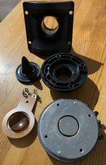
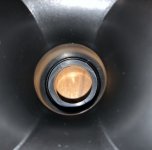
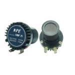
I got some really cheap compression drivers to play with. I can see some flaws in the design and I will try to improve them. Level 1 will be filling the phase plug with hot melt glue and use another horn attachment, since the existing one is plain bad - with a step at the throat and a long section without any expansion.
The air gap is filled with ferrofluid. Is it worth trying to remove it and is that even possible?
Level 2 will be improved 3D printed phase plug and level 3 completely new front - maybe with an integrated horn or K-Tube.
The air gap is filled with ferrofluid. Is it worth trying to remove it and is that even possible?
Level 2 will be improved 3D printed phase plug and level 3 completely new front - maybe with an integrated horn or K-Tube.
Attachments
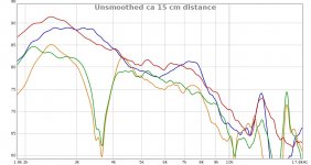
So here are level one results. I do not think it is worth going to level 2 or 3 with these. Yellow is completely stock, green with a wooden horn (which is not perfect, it should be some kind of "Kugelwellenhorn". Blue is with filled phase plug and stock horn and the red is with filled plug and the wooden horn.
So what does this tell me?
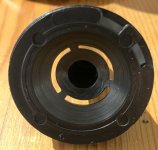
1. the hollow phase plug is the worst example of cost cutting and engineering failure
2. a better horn can improve things
3. the tweeters are pretty useless for HiFi, but might work in some cheap stage monitors
I will maybe try to print some beaming horn with narrow dispersion to see if I can get anything useful out of these. Any suggestions?
So what does this tell me?
1. the hollow phase plug is the worst example of cost cutting and engineering failure
2. a better horn can improve things
3. the tweeters are pretty useless for HiFi, but might work in some cheap stage monitors
I will maybe try to print some beaming horn with narrow dispersion to see if I can get anything useful out of these. Any suggestions?
Attachments
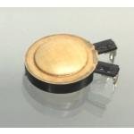
I bought a pair of these neodymium compression 110db NPE comp25 7$ each in Thailand. The inside is similar yours. I transformed them to high efficiency supertweeter > 25khz. I filled inside the diagram some cotton to higher the resonance and dampened. I cut off the tube and shortened the central phase plug to 1cm and rounded off the tip. Inside the chamber I filled mastic (clay used in Kindergarten) the under part of the plug till the openings and tuned to get the resonance 3khz . I made by fiberglass strips dismantled from 400gr/m² roving a 3khz cut exponential horn , winding the strips around a plaster mold and epoxy at each layer ,5 layers at throat 3 at mouth . I use them 1st order cut at 8khz.
See picture corner Chambord with passive radiating sphere
See picture corner Chambord with passive radiating sphere
Attachments
Last edited:
Kokoriantz, your tweeters look much better than mine🙂 I think the diaphragm is too heavy on mine, so there is no chance of improvement in the HF. I will try to print a small horn just as an exercise - if the thread prints fine enough to actually screw on. And I will try cotton under the diaphragm just for fun if that does something.
My diagram type looks the same as yours . In compression drivers the weight of the membrane doesn't count as at high frequencies it breaks down. You can also fill the bullet with clay and reduce the compression volume . As the bullet can hold alone , shape with clay a short horn while listening, it gives an idea what you can do with it.
Attachments
Last edited:
I ordered assortment of replacement membranes for experiments. At least there will be some fun before they end up as targets🙂
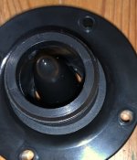
So I measured three different membranes. The biggest surprise was, that the original membrane measured flat up to almost 20 kHz with the front removed. So the next step will be to 3D print a new front plate to accommodate all three types to have a flat front dome tweeter. If that will be successful, a new front plate with horn attachment will follow.
I have discovered the tweeters and wanted to give them the last chance. So I designed and printed new flange to get a dome tweeter.

This is the result. I measured the results and got a pleasant surprise:

Certainly much better. The experiment continues with a 1/2" opening and a small K-Tube. I think I might be able to use these as ambience tweeters.


This is the result. I measured the results and got a pleasant surprise:
Certainly much better. The experiment continues with a 1/2" opening and a small K-Tube. I think I might be able to use these as ambience tweeters.
Last edited:

- Home
- Loudspeakers
- Multi-Way
- Cheap compression tweeter tuning