You are using an out of date browser. It may not display this or other websites correctly.
You should upgrade or use an alternative browser.
You should upgrade or use an alternative browser.
Filters
Show only:
Build the Mark Levinson 23.5 from schematic?
- By FriedMule
- Solid State
- 90 Replies
I know, I know, I could properly buy a Mark Levinson 23.5 for cheaper and perfectly made, but I think it could be fun to build the amp myself from schematics. The project is not to get anything better or equal, but simply the fact that building is fun! 🙂
But is it even possible, I have found this document, but is it enough to a complete build?
(please ignore that the component values is impossible to read)
https://www.audioservicemanuals.com...1369889-mark-levinson-27-5-pwr-service-manual
But is it even possible, I have found this document, but is it enough to a complete build?
(please ignore that the component values is impossible to read)
https://www.audioservicemanuals.com...1369889-mark-levinson-27-5-pwr-service-manual
Newbie - controlling volume on dual TPA3255 PCB
Hi,
I have this on order, I don't need anywhere near 200W@8Ω, I'm going to run it with a lower voltage, say 24V but I'm not sure what to put on the input side for safety during testing, something that restricts it to a low volume, I'll be testing things before I start using a DSP (Camilla), my limited electronics knowledge would lead me to a resistor voltage divider or a potentiometer, what do you use?
On the output side do these amps just work with 2-8Ω then without having to change anything?
Sorry for the newbie questions.
Thanks.
Richard
Questions about adjusting bias and DC offset
- By setiawan
- Solid State
- 5 Replies
I’m looking to replace the electrolytic caps in my amplifier (Akai AA-5510). I’ve heard that you should adjust bias and DC offset if you replace the capacitors in the amplifier stage. Is that right?
For reference this is the schematic for the main amp board:

I have little/basic electronics knowledge so any help is appreciated.
Also, do you need an oscilloscope to adjust bias and DC offset? I only have a digital multimeter.
Thanks
For reference this is the schematic for the main amp board:
I have little/basic electronics knowledge so any help is appreciated.
Also, do you need an oscilloscope to adjust bias and DC offset? I only have a digital multimeter.
Thanks
Miro AD1865R DAC and PSU built and working
- By passive420
- Swap Meet
- 6 Replies
Excellent working DAC with all in one 5V PSU. Comes with basic 5534 op-amps but this sounds just amazing with a certain tube IV stage. This has the SMD version of the DAC chip mounted to a custom designed adapter with 0805 decoupling cap for digital rail under the adapter. ZLH, FM and Elna audio caps.
PSU has high quality low noise TPS7A regs from ldovr. CRC filter.
Perfect simple DAC kit ready to play, needs a suitable I2S source.
SOLD

PSU has high quality low noise TPS7A regs from ldovr. CRC filter.
Perfect simple DAC kit ready to play, needs a suitable I2S source.
SOLD

New member
- By Island boy
- Introductions
- 1 Replies
Hi
I’m Dean from Australia
I love to tinker on speakers and I have been meaning to join this audio site for a while now!! So here I am 🤙
I’m Dean from Australia
I love to tinker on speakers and I have been meaning to join this audio site for a while now!! So here I am 🤙
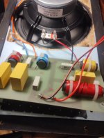
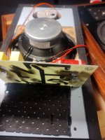
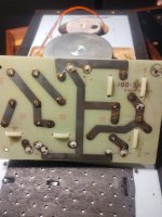
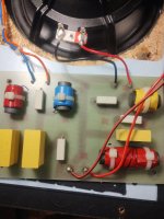
Lentek S4 crossovers
Hi
I'm looking to recap the crossovers on my Lentek S4s.
Trouble is I can't identify the caps or easily make out the values.
See pics attached.
Thanks
I'm looking to recap the crossovers on my Lentek S4s.
Trouble is I can't identify the caps or easily make out the values.
See pics attached.
Thanks
Attachments
The computer thread
- By VenusFly
- The Lounge
- 523 Replies
What are your current adventures in computers?
I'm currently installing ubuntu mate desktop on a raspberry pi 3 so that I can use it instead of my power hungry pc for basic email/web/netflix/vlc/steam gaming streaming tasks.
I have an on-grid solar power system and will turn my old pc into a fileserver and steam game streaming platform so that I can play videogames on my raspberry pi. The fileserver will turn off every day in the afternoon and turn on in the morning to save on power. The raspberry pi will stay on 24/7.
Going to try this trick for a chromium port for netflix: YouTube
I will eventually get a smaller monitor for power consumption reasons but I'm waiting on the energy efficiency of LCD monitors to improve, I doubt I will be able to ever get a 44" LCD television that consumes 25 watts however you can always dream. I currently have a 44" lcd tv hooked up to my main pc but I want to reduce its power consumption greatly and replace it eventually, once technology improves.
I am also in discussions to buy a vintage Apple iMac G3 so that I can play some of the old games that are on that machine that I used to play and explore the performance of the powerpc architecture.
Anyone else? 😎
Looking for Audax HD20B25H mid/bass Driver
Hi
I have a pair of Lentek S4s and one of the drivers has blown.
Looking for a Audax HD20B25H They are Bextrene Type Cones.
Thanks
I have a pair of Lentek S4s and one of the drivers has blown.
Looking for a Audax HD20B25H They are Bextrene Type Cones.
Thanks
Sony TC-127 shutoff
- By gmonstah
- Analog Line Level
- 2 Replies
Hi all,
Does anyone know if the Sony TC-127 automatically shuts off at the end of tape? My newest find does not, but no sense trying to fix a feature that doesn't exist.
Manuals seem to not be available.
Thanks
Does anyone know if the Sony TC-127 automatically shuts off at the end of tape? My newest find does not, but no sense trying to fix a feature that doesn't exist.
Manuals seem to not be available.
Thanks
How do you determine "fL / LFbleak pt" for full-range speakers?
- By Chace
- Planars & Exotics
- 2 Replies
Hello.
For full-range speakers, could you please tell me how to determine "fL / LFbleak pt" for "ESL_line_sectioned_DIY"?
For hybrid speakers, you can probably consider the woofer and slope, but what do you consider for full-range speakers?
If you make it too low, the output sound pressure will be reduced.
Thank you in advance.
Better to reduce gain at DAC IOut or with inverting opamp?
- By esrevinue
- Electronic Design
- 13 Replies
Hello.
I am designing a board to add on to my DG-1000. This board uses a THAT1646 to create a balanced output. The problem is the 1646 comes with a gain of 2, which would cause the audio signal to clip at the rails. The audio signal is 24Vpp coming out of the IOut of the PCM1702 DAC, as calculated by the ±1.2mA current output and the 10k resistor of the inverting opamp following it:
V = 2.4mA x 10k = 24Vpp
I'm wondering if it would be better for SNR to either reduce the feedback resistor of the inverting opamp from 10k to 5k or use an otherwise unused section of an opamp to reduce gain by half before the 1646?
Thanks in advance for any help.
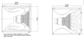
insane question: can a tractrix horn be folded?
- By turboblast
- Multi-Way
- 89 Replies
It seems like the tractrix curve has everything going for it, uses less horn length and mouth, helps with low frequencies, directiveity, smooth phase alignment etc..
But has anyone attempted to fold one? or would the folds inherently destroy the curve no matter what? I can barely draw a tractrix curve unfolded at this point, but im fairly sure I could CNC one with a lot of scoring for bending material. Im even open to alternative materials and methods that could wrap the horn path around the main larger horn mouth itself in a spiral for example.
So far GPT said (with a grain of salt) that I could get down to 60/70Hz with a 20 db gain and 3 times the thow as compared to un-vented.. LOL
Attached are some "very" rough ideas for comment.
Attachments
Driver Selection for Sealed, Single 4" Driver Monitor Speaker
- Full Range
- 20 Replies
Hello all,
I'm looking to build a single monitor speaker like an Avantone, Auratone or Mixcube.
So far I have found (I sorted them based on my own understanding of suitability for this goal):
Dayton Audio SIG120-4 (most suitable, smooth low end roll off, only downside seems peak at 6Khz)
Scan-Speak Discovery 10F/8414G10
Tymphany TC9FD18
SEAS Prestige FU10RB
However, as I am no expert, and the driver, other than the enclosure is the only mission-critical component, so I'd really like your opinions on driver selection, preferably ones that I can buy at soundimports.eu, as I am based in the same city !
I'm looking to build a single monitor speaker like an Avantone, Auratone or Mixcube.
- single 4"ish driver in sealed enclosure with stuffing
- stable freq range between 200~5Khz , with smooth rolloff without requiring a crossover or filter
- as low THD as is practical
- max 150EU for single driver
So far I have found (I sorted them based on my own understanding of suitability for this goal):
Dayton Audio SIG120-4 (most suitable, smooth low end roll off, only downside seems peak at 6Khz)
Scan-Speak Discovery 10F/8414G10
Tymphany TC9FD18
SEAS Prestige FU10RB
However, as I am no expert, and the driver, other than the enclosure is the only mission-critical component, so I'd really like your opinions on driver selection, preferably ones that I can buy at soundimports.eu, as I am based in the same city !
Marcel's RTZ DAC
- By nautibuoy
- Digital Line Level
- 12 Replies
I'm creating a fresh thread to document the progress of my project with Marcel's RTZ DAC.
The original information about the RTZ DAC is here.
I was one of the first builders of the RTZ DAC after listening to Marcel's prototype, which he kindly loaned to me. Two of my fellow UK-based audio DIYers have built DACs to the RTZ design based on hearing the prototype when I took it to a UK meet-up. I'm currently without an RTZ DAC as I have supplied the boards I assembled to others.
I also have Marcel's Valve DAC and ppy's DSC2 DAC as reference points.
In the next few weeks I plan to built two identical RTZ DAC boards - eventually they'll find themselves used in different ystems but in the short term I plan to explore using the DACs with a variety of input arrangements, power supplies and output filters and report my personal perceptions/preferences. Having two identical boards will provide me with a reference point.
Input options I have available include;
I currently have available the original output filter and the simplified version and in time plan to explore some additional modification options.
Anyway, the first thing is to borrow a reflow oven and get the two RTZ DAC boards assembled, hopefully in the next 2-3weeks.
The original information about the RTZ DAC is here.
I was one of the first builders of the RTZ DAC after listening to Marcel's prototype, which he kindly loaned to me. Two of my fellow UK-based audio DIYers have built DACs to the RTZ design based on hearing the prototype when I took it to a UK meet-up. I'm currently without an RTZ DAC as I have supplied the boards I assembled to others.
I also have Marcel's Valve DAC and ppy's DSC2 DAC as reference points.
In the next few weeks I plan to built two identical RTZ DAC boards - eventually they'll find themselves used in different ystems but in the short term I plan to explore using the DACs with a variety of input arrangements, power supplies and output filters and report my personal perceptions/preferences. Having two identical boards will provide me with a reference point.
Input options I have available include;
- Beaglebone Black with ppy's reclocker
- Beaglebone Black with ppy's DSD'it resampler
- Beaglebone Black with TPA Hermes/Cronus reclocker
- Amanero clone with PCM2DSD resampler
- JLSounds i2soverUSB reclocker
I currently have available the original output filter and the simplified version and in time plan to explore some additional modification options.
Anyway, the first thing is to borrow a reflow oven and get the two RTZ DAC boards assembled, hopefully in the next 2-3weeks.
Burning Amp 2023!
- By Tom V
- Clubs & Events
- 668 Replies
YES WE DID! NEW VENUE, PETALUMA COMMUNITY CENTER, PETALUMA CALIFORNIA, SEPTEMBER 30TH-OCTOBER 1ST!
Tickets available here: https://www.eventbrite.com/e/burnin...bby-tickets-695560479117?aff=ebdssbdestsearch
If you would like to help organizing this thing, raise your hand!
-Tom-
Hypex module reliability (UCD)
Hi guys,
I would like to have your feedbacks regarding Hypex amps longevity / reliability / lifespan (especially UCD). Many people have encountered broke or burnt units and it seems these modules could be delicate. At this point I’m wondering if I should still stick to Hypex amps...
My own experience:
I’m using an UCD180HxR based amp since 2015 with 3 ways tower speakers (88db, 8ohms (but 3ohms minimum )). It’s a pre-assembled kit with a SMPS300R and I think everything was nicely set and wired but the supplier. I’m totally fine with this amp, sounds great, black background, plenty of power.
But I had to replace the Hypex modules two years ago, they were starting to produce more and more weird noises to a point they were not safe to use anymore. At that time, I was suspecting the amp was probably running too hot and the modules were cooked. The enclosure is not that big but I optimized the setup, found a cooler space in my rack and used better thermal paste when I replaced the modules.
2 years later, AGAIN, I’m starting to ear some weird noisy blinks when I stick my ear right on the tweeters...
I know this sound, it sounds trivial currently but it will be louder and the amp will probably be good to trash in 6 months.
UCD180 modules aren’t too expensive but if you have to change them every two years it’s still a considerable expense. Recently I was thinking about moving to UCD400 or NCore but don’t know if I can trust these modules anymore.
I have many theories in my head:
1- The load is killing my amp (3 ohms tower with probably difficult cross overs, also a sub connected in parallel). An UCD 400 could be more appropriate
2- I don’t take care of the amp properly. No fancy softstart, no heavy heatsinks, I let the amp turned on for hours even if there’s nothing playing
3- I have some king of ground loop or static in my hifi rack slowly killing the amp...
4- UCD are just fragile modules that degrade and die after 2/3 years ?
Let me know what you think
2SK68A Rank mismatch in Kenwood KA-9100
- By rjb5191
- Solid State
- 5 Replies
Hello all,
I'm looking for some help determining if the N rank 2sk68a (IDSS ~ 6 mA) will be an ok substitute for the L and M rank parts originally supplied in the Kenwood KA-9100
I will attach photos of the circuits with one being the phono input and the other being the control amp input.
I am also hoping that this issue will help me understand JFET's and JFET circuits better so please understand if I make assumptions in what I write here that are totally wrong.
first the phono circuit that specifies L rank 2sk68a's that are currently 2-2.5 mA IDSS parts.

I can only guess how the circuit would react to the higher IDSS parts. But it would seem that with the given values on the schematic, the current flow through the JFET would increase roughly in proportion to the difference in IDSS between parts. However, since the circuit is biased with fixed resistors, the operating points of the circuit would shift. Can anyone explain or model what would happen here, using the higher IDSS parts?
Same here for the control amp input: where they used different ranks within the differential pair although based on the circuit it makes sense why that might be required, I can't say exactly why.

I'm looking for some help determining if the N rank 2sk68a (IDSS ~ 6 mA) will be an ok substitute for the L and M rank parts originally supplied in the Kenwood KA-9100
I will attach photos of the circuits with one being the phono input and the other being the control amp input.
I am also hoping that this issue will help me understand JFET's and JFET circuits better so please understand if I make assumptions in what I write here that are totally wrong.
first the phono circuit that specifies L rank 2sk68a's that are currently 2-2.5 mA IDSS parts.
I can only guess how the circuit would react to the higher IDSS parts. But it would seem that with the given values on the schematic, the current flow through the JFET would increase roughly in proportion to the difference in IDSS between parts. However, since the circuit is biased with fixed resistors, the operating points of the circuit would shift. Can anyone explain or model what would happen here, using the higher IDSS parts?
Same here for the control amp input: where they used different ranks within the differential pair although based on the circuit it makes sense why that might be required, I can't say exactly why.
Replacement Cap - plate amp power supply
I have a plate amp to a REL Studio II (300 watts). I want to replace the power caps, but am having difficulty sourcing them. It seems replacements have a screw terminal or snap fitting. The OEM is a spade connector (solder):
10,000 UF
100 V
22.5 mm spade distance
45 mm diameter case
Height - doesn't matter (plenty of room in the enclosure)
Would someone suggest a replacement and how I can mount it to the board if spade is not possible any longer
Thanks

10,000 UF
100 V
22.5 mm spade distance
45 mm diameter case
Height - doesn't matter (plenty of room in the enclosure)
Would someone suggest a replacement and how I can mount it to the board if spade is not possible any longer
Thanks
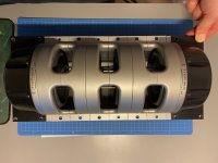
Tymphany LAT 500
- By Msander68
- Subwoofers
- 5 Replies
Hello.
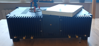
Just purchased this “thing” almost mint condition for 43U$D
Don’t know if it was overpriced or a super deal.
So what shall I do with this? Been googling around but actually do not think I can find anything really useful. Anyone have som suggestions. There is some pictures around the net with this “thing” fitted in different enclosures. I have never before built any sub. Only normal loudspeakers. So this is totally unknown knowledge. I think it looks pretty cool. Well if you have any ideas, suggestions or experience. Please share your thoughts.
Thanks / Sander.
Attachments
Electric guitar tone control can't dump highs anymore
- Analogue Source
- 2 Replies
Can't dump highs, replace a500k tone plus 103 ceramic 1kv, chk all solder jt, chk all conductor continuity, chk all grounding co connectivity, vol a500k works perfect with pss, just cant dump any highs, p90 s are very very raunchy
frustration : replace vol a500k alpha full size since carbon may be fatigued dialed in at 1.8-2.0 tophat knob graduation
frustration : replace vol a500k alpha full size since carbon may be fatigued dialed in at 1.8-2.0 tophat knob graduation
Attachments
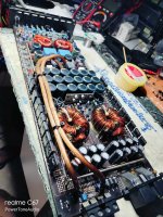
Car Amplifier have power but no sound. Please help me
- By Hackersingh
- Car Audio
- 93 Replies
In this amp there is power and all mosfet and channels are working but no sound and even no humming.
But there are two high wattage resistors or heavy Transistor and they are heating so much,
Please help to find which component is damage in this amp


But there are two high wattage resistors or heavy Transistor and they are heating so much,
Please help to find which component is damage in this amp
Rod Elliot Project 88 question
- By supernet
- Analog Line Level
- 271 Replies
Have anybody built project 88 from Rod`s page? I am interested in sound quality.
Supernet
Supernet
WTB Sowter Type 1465
I'm looking for a pair of Sowter Type 1465 transformers for DAC output. In the US would be preferred.
Build a diy Marantz Model 2 or modern options
- By parkerdiy
- Tubes / Valves
- 9 Replies
Hi, I'd like to build a diy El34 pp amp. Is it worth building a clone of the marantz model 2, or are modern schematics "better"? Such as the Ank amps.
I have the transformers and I'll be building it from scratch.
I have the transformers and I'll be building it from scratch.
Arcam Alpha 9 revival - power supply issues?
- By mca2
- Digital Source
- 11 Replies
After 10ish or so years, I decided I wanted to recreate/revive my first ever hifi set:
Years ago I had upgraded to Cremonas, but when I ran into some Concertinos with original stand, I couldn't resist.
The amp and cd-player had spent their time in a cupboard. The amp worked just fine but sadly the cd-player hadn't survived. When I powered the set, I heard a hissing from the cd-player. When I opened the volume on the amp I was treated with a loud humm. So I'm expecting issues with the power supply.
After opening the case, I noticed some pools of black gooey 'stuff'. Any clue what that could be? Furthermore I saw some swolen elcos. So I guess I need to change a few of those.
As a machincal engineer I can wield a hammer and can (de)solder components, but I'm not really familair with the components. So before I randomly start replacing elcos, any suggestion how to tackle this in a structured way?


- Rotel RA-980BX
- Sonus Faber Concertino Home
- Arcam Alpha 9
Years ago I had upgraded to Cremonas, but when I ran into some Concertinos with original stand, I couldn't resist.
The amp and cd-player had spent their time in a cupboard. The amp worked just fine but sadly the cd-player hadn't survived. When I powered the set, I heard a hissing from the cd-player. When I opened the volume on the amp I was treated with a loud humm. So I'm expecting issues with the power supply.
After opening the case, I noticed some pools of black gooey 'stuff'. Any clue what that could be? Furthermore I saw some swolen elcos. So I guess I need to change a few of those.
As a machincal engineer I can wield a hammer and can (de)solder components, but I'm not really familair with the components. So before I randomly start replacing elcos, any suggestion how to tackle this in a structured way?
Schematic worth to build it?
- By Monstercore
- Chip Amps
- 39 Replies
Hello all, after lurking around for several years. I will start with my first thread.
I read a lot of composit LM3886 amps on this forum but I can not find any schematics worth of building.
I like to build a high power composit LM3886( like 6 x LM3886) amp.
On a dutch forum I found this.

Is it worth building it?

I read a lot of composit LM3886 amps on this forum but I can not find any schematics worth of building.
I like to build a high power composit LM3886( like 6 x LM3886) amp.
On a dutch forum I found this.
Is it worth building it?
Klein Bottle enclosure
- By turk 182
- Full Range
- 41 Replies
after checking out Acme Klein Bottles i was wondering if the shape could be used as an enclosure for a fullrange driver possibly creating a backloaded horn assuming an exit is created.
i do want a klein stein for a beer mug!😛
i do want a klein stein for a beer mug!😛
Hi from Slovenia!
- By slinch
- Introductions
- 1 Replies
Hey folks, I've been lurking for what has to be over a decade, but finally happened upon a project I could use some help with.
Not a DIY-er by experience, but definitely by heart. 🙂
Not a DIY-er by experience, but definitely by heart. 🙂
WTB D1 I/V PCB
Checking to see if someone has an extra D1 I/V board, built or bare, to save a JLCPCB order
Link to the gerbers - https://www.diyaudio.com/community/...0400a-who-have-heard-both.347298/post-6872371
Link to the gerbers - https://www.diyaudio.com/community/...0400a-who-have-heard-both.347298/post-6872371
For Sale D1 I/V PCBs
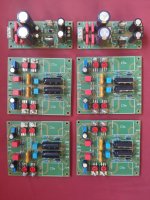
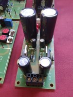
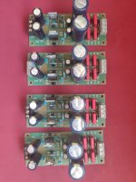
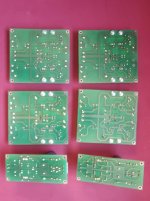
With a heavy heart, I have decided to sell my D1 stage PCBs…
I simply do not have the time anymore to finish all my DIY projects.
I had bought them from Ilias and they came complete with matched IRF610s.
I had finished 4 PSU boards and almost finished 4 of the D1 boards.
The only tasks left is installing one C3 cap and the bigger C5 caps on the D1 I/V boards.
I have used excellent parts (Wima caps, Panasonic FC caps, and Welwyn audiophile 220R resistors on the relevant R8 position.
Please send me a PM if you are really interested.
Attachments


Best Audio Quality PA Subwoofer - Efficiency Aside? Best Approach and Specific Design Recommendations
- By Chendy
- Subwoofers
- 4 Replies
Hello,
I'm not new to large sound systems, but would appreciate the wisdom here.
I want a subwoofer for small events, not home HiFi.
This will be left at a single location, so I don't need to worry too much about weight and efficiency.
But would need to be moved around on site, say between storage and outdoors.
I want something that sounds super musical.
Low harmonic and phase distortion etc.
I don't care about having to EQ the subwoofer.
Not sure how important group delay is either, I could delay the tops with processing.
Doesn't have to go that high, I could put a kick on top.
My understanding is that a sealed enclosure is the best quality, but the efficiency seems a bit too low for me.
If its true that they are at least 4x more volumetrically inefficient.
So question is what is next best simple standard subwoofer topologies?
Are these horn based? Especially front-loaded horns?
And beyond the topology, the devil is in the detail.
Can anybody recommend free high-quality tested designs? Not just hornresp.
Especially interested in simple DIY builds.
I've seen these here, but I'm sure there's loads of community designs I'm not aware of.
https://www.eighteensound.it/en/resources/suggested-designs/
Thanks!
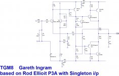
TGM8 - my best amplifier, incredible bass, clear highs, no fatigue (inspired by Rod Elliot P3a)
- By Bigun
- Solid State
- 1247 Replies
(edit)
Note - what started out as an attempt to evolve the p3a has ended up as a complete redesign of every stage. This amplifier is my best. Anybody wanting to build this amp for DIY purposes (only) should find all they need in this thread.
Some useful posts:
#232 - discovery that dual colour LED has insufficient headroom for the ‘green’ side to work (my fix is on #314)
#238 & #242 - discovery of, and changes to deal with cross-conduction at v. high frequencies
#314 - fix to pcb for very first incarnation (corrected on subsequent pcb layouts)
#407 - pcb files and (a now old) bill of materials
#597 - a bill of materials for Mouser
#604 - my as-built schematic (with C3 shown wrong way around, should be installed + terminal to ground)
#632 - a comment on bias for the output (60mA) note original pcb has a silkscreen error with the bias and dc offset adjust labels swapped around
#645 - a note on correct orientation of C3 (shown wrong way on pcb silk screen)
#768 - some photos and comments on how the power devices mount under the board and the use of some TO-126 transistors with legs removed are used as 'spacers'
#772 - some photos and comments on incorporating an output inductor into the wiring
#950 - updated bill of materials (BOM) based on Digikey.ca
#994 - spice file for the amplifier
#1131 - KiCad files from 'longface54'
#1215 - updated KiCad files from ‘jpk73’
Builders: Go slow, solder all the small parts first and clean off the flux before moving on. Read the thread, I know it's long but there's advice in there for you.
Builders Comments:
'Ranchu32': "this is a fabulous amp; one of the best. I love the sense of energy and the dynamic performance, which I feel is somewhat lacking in the basic P3A. But it loses none of the P3A's best qualities: that beautifully smooth and detailed midrange, and crystal clear highs." "the more time I spend with TGM8 the more impressed I am. Having now heard the VSSA, I am equally impressed and it is deserving of the high praise it is getting around here. But your design is in the same league: similar in many respects and subtly different in others. I suspect TGM8 will better suit my tastes"
'Lordearl': "As to the sound - phenomenal, incredibly relaxed, yet still highly detailed! Tempted to use the good channel on my better speakers just to enjoy it for a while! A very inviting sound for sure." "My initial impression (mono only) is the same, the low frequencies are crisp and punchy - never heard anything quite like it. The treble easily rivals my 6L6 ultra linear push pull amp with Tango output transformers, plenty of air, no fatigue (also no apparent dumbing down of the sound!). Makes you realise why you loved audio in the first place!"
'still4given': "You done good Gareth! I can see why you were so satisfied. I've got some Gerry Mulligan playing through it right now and it is beautiful. Thanks for sharing this with me." "It really is very nice sounding. Seems as good as the VSSA and that is one fine sounding amp."
'pronk': "I originally planned to build just two boards but liked the TGM8 so much that I built six (four to power my LXmini and two for my home office). Note these boards are densely populated and have about 30 SMD components. This is probably not something you can throw together in an evening. The end result is definitely worth the effort. This is one of my favourite amplifiers. Sound quality, particularly bass, is excellent. I appreciate the built-in speaker protection which makes this amplifier more of a complete product safe to use with expensive speakers."
'RCruz': "Finally had the opp to listen to it and i am really pleased with the sound...the best bass grip I heard in years"
'auriga2001in': "Thanks for the wonderful amp. I have two amps (BJT, Latfet outputs) running wonderfully for a year now."
'pinnocchio' "This amp has some really good grip on the bass driver, very fast and precise. I haven't done all the tests yet but looking very good so far."
‘Do’: “Amps are working perfectly. I truly love the bass from this amplifier, very hard to believe until you hear it! Solid, in control of the speaker, I mean just perfect!”
'audiorasp': "I really like these amps! They have been powering my LX521's for about month now and I find their presentation to be detailed and powerful, but in a relaxed way, if that makes sense."
'longface54': I decided to go for it. I had some PCBs made, using the published gerbers, and built two amps. Powered each one up on the lab PSU and, bingo! They both worked first time and the DC offset and bias was very stable... Right away the sound had such authority and pace but in a relaxed and musical way with a softness in the upper registers. ... I’m listening as I write so I’m off to turn the volume up... just a little.
’jpk73’: I connected my speakers and played some music: excellent!!! I am very happy 👍🙂.
'chat72': Ok finally they sing!!! Sound good especially high.
Also - I can not edit attachments to the first post, the schematic you see in this first post shows my initial scrawl - not to be confused with the schematic of the as-built amplifier.
Attachments
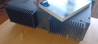
Luxman l550, l570, l570xs class A worth the hassle?
- By Audioweb
- Solid State
- 14 Replies
Hi
My question is is it worth buying Old class A luxman like l570, l570xs?
My fear about these luxman amps is that Output transistors are discontinued and impossible to get.
Also is it True that these class A amps require overhaul (replacing of all caps) every 3-4 years?
So is it worth buying? I read some opinions that some people didnt like luxman l570 sound, described it as glossy/smooth but with poor reproduction of detail
What is Your experience
Thanks in advance. Cheers
How to increase amperage?
- By Jim-Mellon
- Power Supplies
- 20 Replies
My power bank output is 5 volt 2A.
Is there any circuit to increase its ampere without voltage change?
Is there any circuit to increase its ampere without voltage change?
Hi from the UK!
- By pombok
- Introductions
- 1 Replies
Seen loads of helpful posts about dead Cambridge A500s and hoping for my own help.
Cello One. Good Amplifier 15 Watt with TMC and Laterals
- By lineup
- Solid State
- 430 Replies
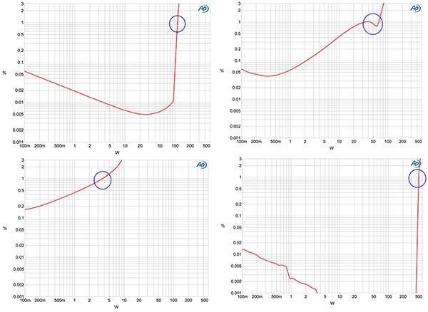
Cello One
All data comes from SPICE simulation.
I leave building this amplifier to diyAudio members.
I can not build it.
Max 15 Watt into 8 Ohm Class AB
TMC compensation
THD 0.00005% at 1 Watt
Easy to find components are used

All data comes from SPICE simulation.
I leave building this amplifier to diyAudio members.
I can not build it.
Max 15 Watt into 8 Ohm Class AB
TMC compensation
THD 0.00005% at 1 Watt
Easy to find components are used
Help, I need to step up 3.2 VDC to 12 VDC (fixed, not variable)
- By Jim-Mellon
- Power Supplies
- 4 Replies
Hey everyone 🙂
I want to power my equipment.
It requires 12vdc.
I want to power it with my LiFePO4 100ah 3.2vdc battery.
Please share with me if you have a circuit for me to build a dc to dc converter in 3.2vdc and out 12vdc.
I need it fixed at 12vdc, not a variable within particular range.
Also, I need it at least 2 ampere, the larger the better.
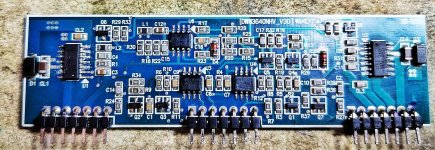
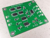
DD M3B Driver board unknown ICs
I am working with a monoblock amp DD M3b. with no output issue. After troubleshooting I found out that their were no gate drive signal on the output Mosfets.
both sides .( 6 FETS on both sides) Power supply section is good, , auxiliary voltage +- 15V dc and 12Vdc on the output section are all present, going to the board. At this point I am suspecting the Drive chip and other IC's on the drive board are deffective as well. But the problem is the IC's are refaced and the part numbers are no way to be read. Can anybody share me the component part numbers of IC's? Attached is the picture of the drive board.
both sides .( 6 FETS on both sides) Power supply section is good, , auxiliary voltage +- 15V dc and 12Vdc on the output section are all present, going to the board. At this point I am suspecting the Drive chip and other IC's on the drive board are deffective as well. But the problem is the IC's are refaced and the part numbers are no way to be read. Can anybody share me the component part numbers of IC's? Attached is the picture of the drive board.
Attachments
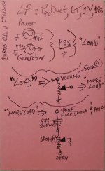
Did anyone try this Class-A 5534 current dumping trick
- By LJT
- Electronic Design
- 8 Replies
Hi, while searching for information on current loading op-amp outputs I stumbled upon this info on the Keith Snook.
https://keith-snook.info/op-amp-class-a-current-dumping.html
Basically, putting an extra resistor between the output (pin-8) and driver output (comp, Pin-5).
Resistor values between 68 and 150 ohm seem OK if one is to believe the web-page.
Did anyone try this trick? Do anyone have some measurements or feedback on sonic results?
Hi from Munich
- By btheiss
- Introductions
- 3 Replies
Hello, I am Bernd (Theiss). I used to work for Joachim Gerhard and Audio Physic. Nowadays I mainly work in measurement and telecommunications, but I still enjoy audio engineering on a DIY level. Great place to get inspiration here!
Searching for ThorstenL original Gainclone schematic
I'd like to know what @ThorstenL original Gainclone was like.
Schematic, please.
Thanks!
@Peter Daniel built it, too
Schematic, please.
Thanks!
@Peter Daniel built it, too
Fender Keyboard 60
- Instruments and Amps
- 19 Replies
Hello guys, a friend of mine asked me to fix this amp, so the problem is basically when you turn it on it will immediately sound/produce/hum that sounds exactly when you have a output transformer bad, so the reason to this been someone changed the 750ohm resistors with 150ohm. I checked the schematic and the amp and i don't see to many other suspects, but since its a model im not familiar with, i wanted to see what you guys think? Thanks a lot
PPSL Sub box at the curb
- By Top Shelf
- Subwoofers
- 4 Replies
Anyone want a free dual 12 ppsl box?
I have it sitting at my curb.

I have it sitting at my curb.
Amp stability - is this stable?
- By ampetrosillo
- Electronic Design
- 10 Replies
So, I'm trying my hand at designing with feedback (just a simple CFB amp).
This is the amp (not a power amp, just an amp):

(Supply is 18V, as shown, through the wiper's action, it provides between 13dB and 36dB of gain).
This is the AC plot.

Taken from the output.
Now, apart from the fact that I don't really understand how the feedback actually works here (the output is in phase with the input, and I'm taking the signal from the output and I'm injecting it into Q1's emitter - shouldn't it actually be phase reversed? But if I try that everything falls apart).
I can see that (according to the simulation at least) there are no nasty peaks and, although not Butterworth smooth, at the lowest gain (and maximum feedback) there are no peaks in the response. That said, there is more than unity gain at well beyond phase reversal. I suspect that if I want to work out the phase margin, I should measure something else (and I know it's just a simulation, but I certainly haven't got a 100MHz oscilloscope anyway...), but the response seems not to have any oscillations going on. If I try and add a 30p cap between, say, base and emitter of Q2...

I expanded the range because there is that "interesting" gain increase at very high frequencies (I don't know if it's truthful at all, anyway it's still below unity gain).
Is this better? Is this CFB design inherently stable even without a cap? Am I even going in the right direction?
This is the amp (not a power amp, just an amp):
(Supply is 18V, as shown, through the wiper's action, it provides between 13dB and 36dB of gain).
This is the AC plot.
Taken from the output.
Now, apart from the fact that I don't really understand how the feedback actually works here (the output is in phase with the input, and I'm taking the signal from the output and I'm injecting it into Q1's emitter - shouldn't it actually be phase reversed? But if I try that everything falls apart).
I can see that (according to the simulation at least) there are no nasty peaks and, although not Butterworth smooth, at the lowest gain (and maximum feedback) there are no peaks in the response. That said, there is more than unity gain at well beyond phase reversal. I suspect that if I want to work out the phase margin, I should measure something else (and I know it's just a simulation, but I certainly haven't got a 100MHz oscilloscope anyway...), but the response seems not to have any oscillations going on. If I try and add a 30p cap between, say, base and emitter of Q2...
I expanded the range because there is that "interesting" gain increase at very high frequencies (I don't know if it's truthful at all, anyway it's still below unity gain).
Is this better? Is this CFB design inherently stable even without a cap? Am I even going in the right direction?
Knowledge Inquiry
- By Jim-Mellon
- Instruments and Amps
- 47 Replies
It there such a thing of old times and otherwise?
What's make it different?
What's the pros and cons of both world?
In view of nowadays builds are smaller in size.
Does the situation in IT sector also applies to amps? Means, that today smaller size computer can beat once a football size computer.
Is it really today smaller amps can beat previous amps which are bigger.
Is it possible for me to have a smaller speaker and amps that can beat my grandad's big one?
Amplifier Design and Tube Rolling
- By Tom Johnson
- Tubes / Valves
- 18 Replies
First off, I hope everyone is having a great day.
I designed and posted this amplifier schematic over at AudioKarma and the first reply was it is a total waste of time and money, just set it up for the tubes you want and be done with it. Also, the real knowledgeable people did not get involved. Below is what I wrote over there after I was told this. I am posting it here hoping for a more scientific review
Thank you for the replies. A little background, and my case in theory.
This amp was designed using all Toroidal Transformers, thus the lower cost.
This all started as a training exercise for me and a challenge to myself to design an input stage that could actually roll the input tubes. As I have no one to sit down with and teach me and a friend who is willing to look things over by eyeballing it.
I was already looking at using new issue Tung-Sol 7581 output tubes and read a few places that they are real nice to 85% and 30 watts plate dissipation. I went with 84%. That puts the KT-88/6550 right at 70% plate dissipation using a 6.6K output transformer.
Then I thought, I could do the phase inverter stage like the input stage and ran scenarios for that. The results were just as good as the input stage. Russian tubes were used as an example for using shields and represent a higher amperage draw, 6.3V, 12AX7 input and 6CG7 phase inverter tubes. The 6N6P also has a higher 6.3V amperage draw and is supposed to be a superior sounding tube and, what if it's not or I want to compare tube sound, I can swap it out to a 6SN7. 6CG7 or 12AU7 with the same amplitude with minor adjustments. The same with the input stage and the 6N2P-EV could probably be changed to a 5751 tube with just a voltage change and maybe it would need a couple minor adjustments or any of the other tubes listed on the schematic for that matter.
It was never about the output circuit, that was just a quaint circumstance. It is about the rest of the amp and how one could find a great sounding, low distortion amplifier by rolling tubes. As for sockets wearing out, use socket savers. As for the output stage, set it up how you want.
All this stuff is a waste of money unless you are loaded so you must look at this as an investment in the future in some way. Adding some switches, trimpots and tube sockets to get something more superior is a minor expense in my opinion. Making it with long lasting parts and love is priceless.
I have changed the schematic to 5751 input tubes and 6550A output tubes with 5k 100 watt 40% UL tapped transformers to start with. I left room on in the chassis so Dynaco A431s transformers can be added at a latter date.
If anyone has the time to look this over, thank you. I will be looking forward to replies.
Regards, Tom
Attachments
Can't chase 60 Hz hum out of sound card measurement setup
- By Charles G
- Equipment & Tools
- 11 Replies
I'm putting together a measurement setup for some tube amps I'm building and having a weird hum issue. I'm using a Focusrite Scarlet 2i2 and REW. Initial setup and calibration went fine using loopback cables. Hooking up to a headphone amp gave a large 60Hz hum (-60dB), though. Some of the things I've tried:
Any thoughts on what I could/should try next?
- I thought maybe magnetic from PS choke to output transformer, so I moved the power supply farther away (3 feet). Zero improvement.
- I thought perhaps ripple, though the amp is fully cascode CCS loaded. Even so I added additional RC filtering. Zero improvement.
- I figured ground loops. So I got an ADUM3166 usb isolator setup, and run the focusrite on battery power. Zero improvement.
- I thought maybe still some weird ground interaction/pickup from the PS. So I got a switcher HV power supply. Zero improvement.
- I thought perhaps the HV supply's rectifier was still causing issues. It has a large output capacitor, so I can literally shutoff and yank the power cord on the supply, leaving the entire amp floating and no operating PS nearby. You can still clearly see the 60Hz hum on the spectrum for 3-4 seconds before the supply drops out. (The filaments are also on battery.)
Any thoughts on what I could/should try next?
Hello from central east coast US
- By jzamo
- Introductions
- 0 Replies
Just trying to ask a question about my syntripps.
Currently running 2x syntripp, 2x C2D, 3x Othorns.
Building On instagram @rva_soundsystems
Currently running 2x syntripp, 2x C2D, 3x Othorns.
Building On instagram @rva_soundsystems
dinosaur intro mandated
- Introductions
- 1 Replies
I am seventy still rocking open g five string brit rock n roll
electric guitars have to be kept operational, so troubleshooting skills, come to this place, maybe fix the technical inoperables
electric guitars have to be kept operational, so troubleshooting skills, come to this place, maybe fix the technical inoperables
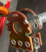
LFD LE IV Signature volume pot replacement
- By jencelo
- Solid State
- 9 Replies
Hi,
I need to have the volume pot replaced. I talked to LFD and asked if I could have something better quality as I think LFD has this volume pot issue apparently. I was told that LFD only recommends this pot. The designer insists that this one is used. I will probably go with the OEM but would still like to know if anyone knows the specs for this pot. All it says A20K on it and looks like it is Bourns brand (at least that's what Google Image search tells me). Thanks.
I need to have the volume pot replaced. I talked to LFD and asked if I could have something better quality as I think LFD has this volume pot issue apparently. I was told that LFD only recommends this pot. The designer insists that this one is used. I will probably go with the OEM but would still like to know if anyone knows the specs for this pot. All it says A20K on it and looks like it is Bourns brand (at least that's what Google Image search tells me). Thanks.
Attachments

USB to AES converter
- By Jcris
- Digital Source
- 23 Replies
I want to convert a usb output from a MacMini to an aes/ebu connection on an active speaker. I’ve seen some devices that do this but they are very pricey. Like this
https://www.matrix-digi.com/product/82/X-SPDIF3 This device costs $500. While I’m sure this would do the job it’s alot more than I need or am willing to pay There must be a simpler more affordable solution. Suggestions or links please. I don’t want anything that will degrade the data.
Thanks,
Jcris
https://www.matrix-digi.com/product/82/X-SPDIF3 This device costs $500. While I’m sure this would do the job it’s alot more than I need or am willing to pay There must be a simpler more affordable solution. Suggestions or links please. I don’t want anything that will degrade the data.
Thanks,
Jcris
For Sale High Resolution DAC. Lynx Audio D-35.
For sale a high restitution DAC Lynx Audio D-35 based on AD1862. This is by far a best implementation of AD1862 . PCB is 4 layers with a high grade components.
Asking 300US plus the shipping
Asking 300US plus the shipping
Attachments
![IMG_3820[1].JPG](/community/data/attachments/1262/1262382-114303ee7de34ba55792c5befbdd672d.jpg?hash=EUMD7n3jS6)
![IMG_3821[1].JPG](/community/data/attachments/1262/1262383-39ae24dd2dc97bba0b5741171303005c.jpg?hash=Oa4k3S3Je7)
For Sale AD 1862N-D and AD811
I have for sale used and 100% working condition pair of AD1862N-D. Grade D is a selection for Denon manufacturer. There was a blue ink on engraved massage ( check mark by Denon) which I tried to clean, hence its a bit blur.
Also a new pair of AD 811AN. Asking 100US for evertyhing plus the shipping.
Also a new pair of AD 811AN. Asking 100US for evertyhing plus the shipping.
Attachments
![IMG_3811[1].JPG](/community/data/attachments/1262/1262375-01b4f4607724c554d743ecbb35e546e5.jpg?hash=AbT0YHckxV)
Thonet & Vander - Kürbis, TDA7265
- By PhantomBox
- Parts
- 2 Replies
Hi guys.
A friend gave me a
Thonet & Vander - Kürbis monitor for repair that turned on but would not sound. After checking the main amp board, I found an exploted ceramic cap between two 4700uf 25v filter caps, a burned 470R resistor, an a black mess that couldn't possibly come from just this exploted cap.
It has a TDA7265 inside. I managed to rebuild the pcb (kind of.... ). The TDA7265 does produce some sound but it's way to low for 25w.
Voltage at the filter caps is +/- 20 VDC.
Maybe I missed something.
Or the Tda7265 is defective.
Any ideas?
DIY I2S to simultaneous converter PCB
- By ryanj
- Group Buys
- 155 Replies
Thanks to John Brown from ECdesigns for sharing his work.
This PCB is based on schematics posted here.
PCB Order Form
V1:
BOM
Schematics
Comparison mp3s - I recorded the same song twice, once using my old setup, and then with the new PCB installed. Headphones will make it easier to hear the difference.
Using Iancanada I2S to PCM PCB
DIY I2S to SIM PCB
The V2 PCB is now avaliable.
This version has inverted data outputs to enable balanced operation - can run up to 4 x D3 PCBs in dual balanced operation, and 2 x D3 PCBs in dual mono/parallel operation.
V2:
Schematics
BOM
V2 Photo
Attachments
Newbie
- By Godman57
- Introductions
- 1 Replies
Greetings from Luxembourgg!
I'm a technical support anaylyst
I'm
Glad to be here
I'm a technical support anaylyst
I'm
Glad to be here
Greetings from Greece!
- By gio4
- Introductions
- 3 Replies
Hello!
I am happy for the acception!
I hope I will find a lot of helpful ideas and suggestions.
My Hifi Collection
Main Set:
Technics SL-D2 turntable
Technics SU-Z2 integrated amplifier
Technics ST-15 receiver (rare)
Technics SB CS6 speakers
SANYO RD 5006 deck
2nd Set:
Sansui P-900 turntable
Technics SU-Z2 integrated amplifier (another)
Chinese Bluetooth Audio Adapter with FM Radio
Syncom by Bose speakers
3rd nostalgic Set:
Dual 1224 turntable
Dual P60 amplifier
4th Set for the country house
AKAI AM-U11 Stereo Integrated Amplifier
JVC T-K100L Tuner
Pioneer CS-555 speakers
unconnected:
AIWA M200 deck
Marantz SR 7300 surround receiver
Technics STG470L PXS - Quartz Synthesizer Stereo Tuner
JVC SP-E35BE... speakers (temporary connected with the 4th set)
Temporary Set:
Technics SA-5070 Stereo Integrated Amplifier
temporary connected to:
Technics SB CS6 speakers
ARCAM phono board (DIVA A85, FMJ A32 etc.)
- By mayky
- Solid State
- 18 Replies
Hi!
Does anyone have a good quality picture of the Arcam phono board? Both sides, soldering and the parts side.
Does anyone have a good quality picture of the Arcam phono board? Both sides, soldering and the parts side.
- DIVA A85
- DIVA A90
- FMJ C31
- FMJ AV8
- FMJ AV9
- FMJ A38
low sound on a Peavy amp with a Hammond 1650T
- By nanchangbob
- Instruments and Amps
- 6 Replies
A friend asked me to help him with his Peavey amp that wasn't working and he went to a few shops over the years and he didn't have any luck. When you tried to play sound through it the B+ dropped way down and drew excessive current. I found the output transformer was shorting under a load. I hooked up a Jolida transformer from an old amp I had laying around and everything worked as it should. But it's only a 50 watt transformer and this amp is 100 watts. He ordered this Hammond 1650t and I hooked it up for 8 ohms. You tie the green wire with the green/yellow and the black with the black/yellow take the positive off the yellow and hooked speaker ground to the black and it has low sound coming out. I did hook the Jolida up a second time to make sure I'm not crazy and it works great with plenty of volume.
This transformer is a bit different than the ones I've used in the past as the extra winding is added to allow it to be used with more power I believe? Am I missing something and just not hooking this thing up properly? I'm inputting a 1 khz test, I even tried just hooking it up as a 4 ohm and taking the positive off the green/yellow and it seems only slightly more sound. Thanks for any help or guidance you can provide. I did check the preamp section and the signal passes through clean and all the voltages and bias are good and stable.
This transformer is a bit different than the ones I've used in the past as the extra winding is added to allow it to be used with more power I believe? Am I missing something and just not hooking this thing up properly? I'm inputting a 1 khz test, I even tried just hooking it up as a 4 ohm and taking the positive off the green/yellow and it seems only slightly more sound. Thanks for any help or guidance you can provide. I did check the preamp section and the signal passes through clean and all the voltages and bias are good and stable.
Attachments
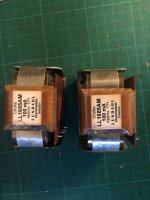
For Sale Lundahl LL1685AM amorphous chokes
- By Geluidloopt
- Swap Meet
- 7 Replies
Selling 1x pair of Lundahl LL1685AM, in like new condition
17H, 100ma
Amorphous core
SOLD
Will ship worldwide
17H, 100ma
Amorphous core
SOLD
Will ship worldwide
Attachments
WTB A pair of those Sony Tamradio output transformers, Or Magnaquest RH 5k
Hey guys, so over the years I’ve had multiple pairs of those Sony transformers, and sold all of them on the forum here. Now I need a favor, need one pair for a project I’m working on. Can anybody help me out?
I would also be interested in a pair of those magna quest Robinhood transformers? The small ones, 5k to 8 ohms….
Or even take a pair of those akai 5k reel to reel transformers. I could pay a fair price, or we could do a trade, I have hundreds of new old stock tubes, other transformers, etc..
Thank you in advance!
-mac
Intro, Hello form PHX
- Introductions
- 2 Replies
ET2 IFF tech USN 87-93, currently working in avionic IFF (TCAS Transponder) systems. Car audio has been my motivation in learning electronics. I am learning to repair old car amps, Alpine Rockford Orion. I learned 6 step of troubleshooting from the USN, digital processors are my strength, good at RF and switching power supplies. I have built and sold clone guitar distortion pedals.
Measuring DC offset of a PA150 (shine7)
- By mrjayviper
- Chip Amps
- 2 Replies
Do I need to connect it to the power supply and mount the chips into a heatsink?
Thanks
Thanks
Questions of faith - reflections on your own taste, thoughts about right or wrong!
- By hbtaudio
- Solid State
- 362 Replies
offspring
Before the Eisenport thread gets completely lost, I would like to open a new platform for all opinions at this point
regarding the disharmonies.
On the one hand, there are advocates of the symmetrical arrangement of components between the rails (in the complement) and on the other, advocates of the minimalist JLH proposal.
Have fun,
HBt.
Attachments
Anyone using the FaitalPro STH100 waveguide?
Looks like an excellent small guide that should hold pattern control to mate with a 6" woofer. The narrow size is a nice option for vertically challenging speakers.
NAD 3020i, 600 mV DC & no sound on left channel
- By Momato
- Solid State
- 26 Replies
Dear all
I would really appreciate your help.
I just purchased a cheap 3020i.
I started by measuring and trying to adjust bias and DC offset. I de-soldered the short across R455 and R456 before adjusting bias to 30 mV.
All 4 trim-pots measure ok and are adjustable. Right channel OK (adjustable to 0 mV DC and plays).
Left channel no sound and DC >600 mV.
The preamp is fine and plays in both channels.
Could you help me fault find? Where do I start? I have a mulimeter and an ESR meter. And I can kinda follow the schematic with some help 🙂
Thank you - Morten / Denmark
Attachments
15in Dayton Subs great for open baffle
- By Cooper60hz
- Swap Meet
- 1 Replies
Local pick up only
Seattle, WA
4 available
$200 each
https://www.parts-express.com/Dayto...Excursion-Subwoofer-22-ohm-295-292?quantity=1
Seattle, WA
4 available
$200 each
https://www.parts-express.com/Dayto...Excursion-Subwoofer-22-ohm-295-292?quantity=1
Attachments
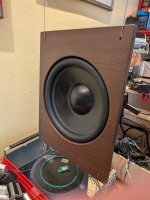
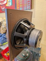
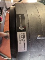
What am I hearing
- By rogerayotte
- Music
- 14 Replies
I have been plagued by something I hear on occasion. It sounds like a fuzzy distortion, but only on select music.
Recently, I heard this and got up and closer to the speaker. It sounded like noise from the mouthpiece of the saxophone. Is that a thing?
Roger
Recently, I heard this and got up and closer to the speaker. It sounded like noise from the mouthpiece of the saxophone. Is that a thing?
Roger
For Sale Toshiba 2SC2459-BL (mini version of 2SC2240-BL).
I have a full box of these transistors in case anyone needs them.
$0.15 ea (min.100 pcs) or
$0.1 ea (min. 500 pcs).
Shipping would be flat @$10 worldwide (up to 500 pcs).
PM me if interested
Thanks for looking!


$0.15 ea (min.100 pcs) or
$0.1 ea (min. 500 pcs).
Shipping would be flat @$10 worldwide (up to 500 pcs).
PM me if interested
Thanks for looking!
15V Regulators PSRR Shoot-out in SPICE. Super Regulator is a winner
- By lineup
- Power Supplies
- 10 Replies
PSRR, power supply rejection ratio, is a pretty important parameter for a regulator.
This test was done with 21V input and 15V output in SPICE. The load was 100mA.
At the input was a signal 1kHz 300mVp-p.
The level of this signal was recorded at the output. The difference is expressed in dB.
The Super Regulator is outstanding according to my test.
LT1085 and LM7815 had somewhat poor PSRR at 1kHz.
LT1085 has a little better result at 100Hz
Result PSRR at 1kHz
142dB - Super Regulator, see image 1
125dB - My TL431 Regulator, see image 2
80dB - LM317
66dB - LM7815
62dB - LT1085
Attachments
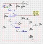

For Sale Pair of USSA 5 25W populated boards + 2 x XRK RTR SSR Speaker Protection + 2 x Micro audio SMPS500-CLA
Due to health issues, I can't complete this project so it's here for sale.
I originally bought these from someone on here, the initial thread with details is https://www.diyaudio.com/community/threads/pair-of-fully-populated-ussa-5-25w-class-a-board.377760/. Pictures are on the thread, I've attached some pictures of the speaker protection boards which are from XRK, the version before this: https://www.etsy.com/uk/listing/932...41&click_sum=2d3298d9&ref=shop_home_active_12
2 x USSA 5 pre populated boards assembled by the designer Fab (see link above for details).
2 x New and unused Micro audio SMSPS500 - CLA, Aux voltage +-12 VDC, Output voltage +-25 VDC, with Mundorf upgrade
2 x XRK speaker protection modules
Looking for £500.
Based in Bristol, UK.
Collection preferred but can ship within the UK.
Altec 420A BiFlex - D’Appolito?
- By gubelmo
- Full Range
- 17 Replies
Good morning everyone,
I am an Italian enthusiast and this is the first time I have written, sorry for any English mistakes.
I've been having fun with diy speakers for fifty years.
I am now in possession of two pairs of Altec 420a biflex.
I have seen the features and different achievements on the web.
But I have a particular idea:
In your opinion, is it possible to make a speaker with a D'Appolito type configuration with a possible tweeter in the center?
I also have two AMT1a and JBL 075 tweeters.
Programmable electronic crossover , biamp.
I'd like it in open baffle, maybe paired with the subwoofer I have: SVS PB16 ultra.
Or in a closed box even of large cubic capacity, I have no problems with space.
Thank you for your opinions.
Corner, sealed, speaker revisiting
- By GremR
- Full Range
- 16 Replies
During the mid 70's I was involved with a small amateur theatre built in part of a Victorian house. As part of that install there were a couple of loudspeaker baffles installed on the wall, left and right sides of front-of-house, for interval music and some ambient sounds. The corner of the two walls became the speaker walls, with only the triangular tops and bottoms of the cabinets made to complete the sealed enclosure. The sound of that installation was excellent, with a nice warmth to the bass, helped by the wood, stone and velvet of the theatre auditorium. Although we ran them with just a 30w/channel amplifier there was more than enough sound for a good thunderstorm or party music.
That all said, I started again looking into corner speaker designs wondering why more use isn't made of using a solid brick wall for two of the speaker sides in a triangular shape. All design notes I have looked at suggest the 12dB boundary effect bass lift (or18dB if in the corner of three boundaries) is mostly undesirable, and I would agree, so why did ours sound so good... even without reducing low frequencies on the amp?
I've attached the only [very rough] picture I could find showing one speaker in situ from those days.

The speakers were actually the units from the KefKit 1 (B200 and T27+ crossover), and the baffle size was approximately 14in x 36in (35cm x 90cm), which would give an internal volume of around 1800 cu.in (~30Litres). From the Kef specs the recommended volume for the speakers was 21litres.
Would anybody with more knowledge of speaker acoustics be able to advise why they sounded so good yet this design is not made more of these days?
That all said, I started again looking into corner speaker designs wondering why more use isn't made of using a solid brick wall for two of the speaker sides in a triangular shape. All design notes I have looked at suggest the 12dB boundary effect bass lift (or18dB if in the corner of three boundaries) is mostly undesirable, and I would agree, so why did ours sound so good... even without reducing low frequencies on the amp?
I've attached the only [very rough] picture I could find showing one speaker in situ from those days.
The speakers were actually the units from the KefKit 1 (B200 and T27+ crossover), and the baffle size was approximately 14in x 36in (35cm x 90cm), which would give an internal volume of around 1800 cu.in (~30Litres). From the Kef specs the recommended volume for the speakers was 21litres.
Would anybody with more knowledge of speaker acoustics be able to advise why they sounded so good yet this design is not made more of these days?
For Sale Complete TagMcLaren Documentation
I have four complete Service Documentation binders on their Power, Pre, Tuner, Integrated and CD products.
See front of inserts to verify which products are included.
These are quite heavy, maybe 1-2kg. I guess the shipping will be noticeable.
€100/each + shipping at cost.
EU only please.
R
See front of inserts to verify which products are included.
These are quite heavy, maybe 1-2kg. I guess the shipping will be noticeable.
€100/each + shipping at cost.
EU only please.
R
Attachments


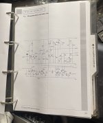

hello!
- Introductions
- 3 Replies
hi! im new here, really interested in designing amplifiers and bespoke multichannel audio systems for art projects. im completely self taught so please be nice
SPL trace not showing up in VituixCAD
- Software Tools
- 3 Replies
Greetings. I generated my first FRD file using ARTA. When I open the file in Notebook, I see three columns, though they do not have headers! They look like frequency, dB and phase. I imported said FRD file into Vituix CAD. The phase data is there, but the SPL data is not.

When I right-click of the upper left graph (where I believe SPL should be displayed) and choose "traces" the dialog box does not have a box next to "driver #1 magnitude".

I'm stumped. I can't find anything in the manual which covers this.
When I right-click of the upper left graph (where I believe SPL should be displayed) and choose "traces" the dialog box does not have a box next to "driver #1 magnitude".
I'm stumped. I can't find anything in the manual which covers this.
Load more
Projects by fanatics, for fanatics
Get answers and advice for everyone wanting to learn the art of audio.
Join the Community
507,507
Members
7,875,107
Messages