I am working with a monoblock amp DD M3b. with no output issue. After troubleshooting I found out that their were no gate drive signal on the output Mosfets.
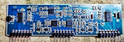
both sides .( 6 FETS on both sides) Power supply section is good, , auxiliary voltage +- 15V dc and 12Vdc on the output section are all present, going to the board. At this point I am suspecting the Drive chip and other IC's on the drive board are deffective as well. But the problem is the IC's are refaced and the part numbers are no way to be read. Can anybody share me the component part numbers of IC's? Attached is the picture of the drive board.
both sides .( 6 FETS on both sides) Power supply section is good, , auxiliary voltage +- 15V dc and 12Vdc on the output section are all present, going to the board. At this point I am suspecting the Drive chip and other IC's on the drive board are deffective as well. But the problem is the IC's are refaced and the part numbers are no way to be read. Can anybody share me the component part numbers of IC's? Attached is the picture of the drive board.
Attachments
Is the driver board installed or not as of now?
Do you have ±5v feeding the driver board?
The 12v should be 12v referenced to the negative rail voltage.
Do you have ±5v feeding the driver board?
The 12v should be 12v referenced to the negative rail voltage.
I saw 5 volts but not sure of 12 volts with reference to the negative rail. As of now the board is not installed. Can I measure this voltage without the board installed. Can you please share me as well, the output pins signal and voltages of each pin of the board when installed? Thank you very much Perry again for the help. I read , this in your guide tutorial which I had, but my PC computer was corrupted. The thing is I misplaced the file , need to look at it.
You can get a new copy if you need it. Email me.
babin_perry@yahoo.com
I don't have a list of all voltages because the voltages change with rail voltage and what you use as a reference.
babin_perry@yahoo.com
I don't have a list of all voltages because the voltages change with rail voltage and what you use as a reference.
Attachments
Good morning, Perry
I had check all the necessary voltages of the driver board pins (installed on board) and it seems all are fine except for pin 6 and 16 (shutdown pins) which is 0.4V with respect to ground. So i believed this pins are pulling the driver to shutdown and not giving the gate drives. I replaced for the second time the drive IC's IRS21844s from DigiKey, bu still with no luck. I can see as well PWM on Pin1 of the drive IC's and VCC's 12V are fine. I had checked everything on the drive board, and to the best of my knowledge all components are fine. So i believed a protection ckt outside the drive board is pulling it down. Is there any part of of main board ckt. i had missed & should look at to bring the SD pins up to 4 or 5volts that might bring the drive board alive. Please advice. Thak you.
I had check all the necessary voltages of the driver board pins (installed on board) and it seems all are fine except for pin 6 and 16 (shutdown pins) which is 0.4V with respect to ground. So i believed this pins are pulling the driver to shutdown and not giving the gate drives. I replaced for the second time the drive IC's IRS21844s from DigiKey, bu still with no luck. I can see as well PWM on Pin1 of the drive IC's and VCC's 12V are fine. I had checked everything on the drive board, and to the best of my knowledge all components are fine. So i believed a protection ckt outside the drive board is pulling it down. Is there any part of of main board ckt. i had missed & should look at to bring the SD pins up to 4 or 5volts that might bring the drive board alive. Please advice. Thak you.
If you place the black meter probe on the secondary center tap of the transformer or on either of the negative speaker terminals and the red probe on the output (relay) side of each of the output filter inductors, do you see more than a fraction of a volt of DC voltage?
What are you using to install the ICs? hot air or a soldering iron?
Does the protect LED ever switch off and go to green?
What are you using to install the ICs? hot air or a soldering iron?
Does the protect LED ever switch off and go to green?

@Perry Babin
your knowledge of car amps is simply incredible. Even more that you share it here. Thank you.
your knowledge of car amps is simply incredible. Even more that you share it here. Thank you.
It powers up green at once. I solder IC's with hot air in the short possible time and in in the past i believed had done it right or just lucky in soldering the same Ic's and sucess in repairs of the same drive board. So i believed , i had done it right today. Furthermore, do you mean DC offset is shutting the drive board down, What is the allowable DC offset of this mono amp?
BTW I also replaced the LM293, TL072 and LM311 all from Digikey. I can see as well PWM to pin 1 of each drive IC's.
Hot air puts too much heat into the body of the IC and the 21844s are especially sensitive to heat. Why not use a soldering iron? It's better in virtually every way.
I want the DC voltage to see if it's possible that the DC is causing a problem.
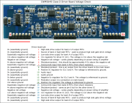
Does your amp use the D1302 in location Q52 on the attached diagram? If so, pull it and check it carefully for open/shorted junctions as well as leakage?
Check Q51 (as described above) if your circuit is the same?
I want the DC voltage to see if it's possible that the DC is causing a problem.
Does your amp use the D1302 in location Q52 on the attached diagram? If so, pull it and check it carefully for open/shorted junctions as well as leakage?
Check Q51 (as described above) if your circuit is the same?
Attachments
Dc voltage output 0.0050V at speaker terminal. Yes there is similar shutdown ckt, I checked the D1302 (Q52) ,puled it but its OK. there is no Q51. By the way there is a fraction of Red light before it goes to Green, any indication it would give?
Are the relays engaging?
Measuring at the inductor output measures before the relays so it's a good number, regardless of the relays.
Is there an equivalent of Q51? The designation may be different but there should be a high-voltage transistor with the same circuit connections.
Measuring at the inductor output measures before the relays so it's a good number, regardless of the relays.
Is there an equivalent of Q51? The designation may be different but there should be a high-voltage transistor with the same circuit connections.
sorry for the late reply, just went on leave for a couple of weeks. Upon checking thoroughly the board, yes there is a Q51 (A1381) separated located in the power supply buffer circuit, funny thing is, it was not there, somebody, perhaps the first technician took it off. I had ordered the part. once i received , i will fix it and update you Perry. Thank you.
- Home
- General Interest
- Car Audio
- DD M3B Driver board unknown ICs