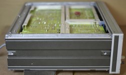
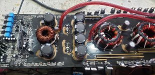
Any manufacturers still using LM3886 in their current designs?

Are there any commercial manufacturers still using LM3886 or similar chip amps in their current designs?

If not, why commercial manufacturers shy away from it?

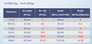
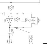
Also the above search lead me to these two patents. I wonder what they are patenting? Their specific modifications to the Typical Application circuit?

Like the Op-Amp buffer?

CN106953607A - A kind of single channel audio power amplifier based on LM3886
- Google Patents


CN105048976A - Power amplifying circuit based on LM3886 chip
- Google Patents

How can I best waterproof speaker fronts for boat use?

I have found four Wharfedale Pro Titan 8 mini PA speakers that I am going to use in my boat for fun. I take heavy metal fishing trips with the boys every now and then, and the 6x9 JBL marine speakers are a bit to weak to really blow the fish out of the water. 🤣 This is how the boat looks with the front 6x9:

1692385106866.png
1692384927438.png


There are a pair of the same type in the rear, barely visible in the back on the closeup. These new speakers are only a little bit bigger than the 6x9 with boxes, but handles much more power. They are meant for outdoors PA use, but not with a direct, heavy water spray like heavy blowing rain or spray from using the boat in 30 knots in waves (they are IP45 rated, but I don't trust that fully).

So my plan is to hang them horisontally under the roof, where the boxes for the 6x9 are now, and build open top 2 mm aluminium sheet boxes around them, bolted to the roof. That will take care of side and rear splash, the problem is front splash for the front speakers, and rain, when the wind comes from the wrong direction and drives it underneath the roof.

I was wondering if it's possible to use alumium sheet as fronts and then have cutouts where the drivers are. But the water resistance is the problem. I would either have to use a kind of a lid and remember to put that in front of the boxes when I dock and remove them again when I'm going out and want some tunes, or find a kind of material that will mostly stop the water from coming in to the speakers. Would for instance a double layer of Gore Tex work for that?

Help: over-sensitive volume pot on Chinese DAC

Hi everyone. I received an inexpensive "Rod Rain" Chinese DAC 2 days ago, and although it sounds nice, normal listening volume is only about 9 o'clock on the volume knob. Is there any chance I can simply replace the pot to give me better control? Having only from 7 o'clock up to the 9 or 10 o'clock knob position means precise adjustment isn't very easy.

I have no idea what the value of the pot is or how it works in the circuit. I asked for a schematic and was denied. A picture of the board is all I have. Note that the op-amps are 4 x OPA1612, not the ones shown in the picture.

I am using the digital coaxial input and the left-right RCA jacks output to my Dynaco ST-70 series ii amplifier.

It works, and I like the way it sounds, but the volume control issue is annoying. I am not an electronics expert or engineer - just a novice with a multimeter and a soldering iron - so I don't know if this is something I might be able to fix or what the fix might be. Suggestions welcome. 🙂

Link the to product: https://www.aliexpress.us/item/3256802716154447.html


DAC.JPG

Replacing 4 ohm drivers with 8 ohm drivers (Wavecor WF182BD03/04)

I have been trying to source the Wavecor WF182BD03 for a project, ufortunately without luck. Instead I have found the Wavecor WF182BD03 which seems to be the "same" model, just 8 ohm instead of 4 ohm.

Is it possible to calculate which modifications would be needed in a filter designed for the 4 ohm version in order to use the 8 ohm version instead?

https://www.wavecor.com/html/wf182bd03_04_07_08.html

About Zobel circuit

I know that the Zobel circuit is to maintain a certain impedance of the load of the speaker at high frequencies. When I test the circuit, the way to measure the impedance is (after measuring the output AC voltage, divide it by the output AC current), but After I came out on the side, whether there is a Zobel circuit or not, the AC current will decrease as the frequency increases. In this way, the impedance will continue to rise, so I don't understand why the Zobel circuit has no function.
Below is my circuit diagram and measure,R9 and L1 are the resistance values of the speakers measured by me.

Attachments

  • 1693020920004.png
    1693020920004.png
    16.4 KB · Views: 218
  • 1693021680768.png
    1693021680768.png
    95.7 KB · Views: 217

Outside The Box

In this vidio of the 2021 BAF Nelson makes a little talk starting at 12:40 called Outside The Box where the main
discusion was about injecting some extra curent into the output stage of an amplifer. But at 20:10 Nelson pipes up and says
" But wait there's more " at this point he describes having some DC bias voltage in the speaker voice coil to lower speaker
distortion. He makes a point that about 1V of DC in the voice coil shouldn't harm most speakers Oh I know this sounds
like herisy but after all the title of the talk was Outside The Box. So this makes me wonder if some of us building a MOFO
using the 193T inductor or an inductor with a lower DCR do we realy need that output cap after all.

Login to view embedded media
  • Like
Reactions: ranshdow

What is the best way to measure transformer output?

Transformers, despite being the heart of every one of these treasured electronic things, are still something of a black art to me. In discussions here about renovating my old components, I've been told to build new power supplies in outboard chassises to reap the benefits of lowered noise, most notably in the Big Sky Adcom thread. I'm ok with the idea, but what if I don't have the value of the original transformer and I decide I want a nice shiny new one without any de-lamination? How do I measure the output of the original transformer to find out the needed value for the new one? Is it just as simple as knowing the output voltage(s) and applying a formula?

FC100 amp looking for a home.

I have an FC 100 (WTB Fc-100 parts). It worked no problems for a few years, but one channel now eating fuses. I have no facilities or the knowledge to track down the issues. I'm offering to any interested parties - FREE. The only catch is you have to arrange to pick it up (it's heavy). I live in the San Diego area.

I built 2 of these - one working, one that went dead after a few years. I'm scaling back and don't have test instruments. The custom transformers alone are valuable (25V@5.2amp/34V@ 0.235).

same deal for the pair

sheldon

Attachments

  • IMG_1607.JPG
    IMG_1607.JPG
    460.7 KB · Views: 310

Confused by tube data (transformer impedance changing with voltage)

Was looking over the N78 tube info http://www.r-type.org/pdfs/n78.pdf and saw something that confused me. Triode AB with 300v needs a 5k output transformer but at 350v it calls for an 8k transformer.

1) Why did the needs of the transformer change so much? Did they just try an 8k transformer and that combo of B+ and current is what was needed to get the distortion that low?
2) Is there a consistent relationship across tubes that you can use to figure out what operating points to use when you have an 8k transformer instead of a 5k one? Or is that always to be found using the tube curves somehow?

3) Aren’t they missing a lot of info to go along with the distortion measurements? Surely different transformers, topologies, etc. will affect the final number right? What did the manufacturers assume when they post distortion figures like that?

Thanks for any help. Still trying to figure out how to read tube data.

DIY phono cartridge

Hello
I am making a phono cartridge as per following specs:
1) micro ridge stylus with sapphire cantilever
2) rubber dampers
3) Mild steel gold plated poles/ yokes
4) 0.027mm pure coper enamelled wire
5) samarium cobalt magnets
6) cartridge body/base made of titanium.

i have finished making MC cart but it is sounding very harsh.
Does anybody have suggestions.

Attachments

  • BDD3B20E-BE11-4B98-A931-7794E47393A2.jpeg
    BDD3B20E-BE11-4B98-A931-7794E47393A2.jpeg
    449 KB · Views: 1,143

Should I replace unknown-hour tubes from 2001 that came with an amp I bought?

The amp is an Audio Research D70 MkII. The tubes are Svetlana branded with "01" date codes. Beyond that, I have no idea how many hours are on them. Everything seems to work properly, no arcing or sonic issues.

Should I have them tested? Should I replace them with new? Should I run them until they start causing problems?

Voice coil inductance calculation with Kr, Ki, Xr and Xi

Do someone have tried to calculate voice coil inductance with the Kr, Ki, Xr and Xi parameters published in ZMA files, as those published by Parts Express for Dayton Audio woofers?
I tried with bad results.
You may like to see my calculations in attached Excel spread sheets. I do hope you don't mind that are in spanish.
I tried both models: one from J. R, Wright (An Empirical Model for Loudspeaker Model Impedance) and other from Marshall Leach (Loudspeaker Voice-Coil Inductance Losses: Circuit Models, Parameter Estimation, and Effect on Frequency Response).
In the file named "Leach-Wright_3a" I've tested Kr, Ki, Xr, Xi Wright's parameters of the DSA175-8 woofer to calculate real and imaginary values of Zem of the motor impedance model, but when I add them (as complex numbers they are) to Re (the DC coil resistance), and Zms (the electric equivalents of mechanical mass, spring and damping of moving parts), the values obtained for Zvc of the voice coil, they disagree with those published in the ZMA file. This is evident in the plot of the calculated values over the impedance graph published with the specs.
In the same file, I calculate the n and K parameters of the Leach's "lossy inductor" model. With them, I get good agreement with the ZMA file values for the cited woofer.
In the file named "Leach-Wright_3b" I get my own values for Kr, Ki, Xr, Xi Wright's parameters, in accordance with his paper. The situation changes to "good agreement" with published data.
I did a second test with published and calculated values for the RS150P-8A woofer, also from Dayton Audio. Again, I got good agreement with values of Wright's parameters calculated by me and not with those published.
What could be happen?
I would like to read your comments.
Kind regards.

Attachments

Chinese ES9018K2M I2S DAC

Hi all.

I bought this DAC from aliexpress.

I connected a 12V DC power source and also connected the I2S lines and GND to a Raspberry Pi 3 with Volumio. In playback options I selected Generic I2S DAC as the DAC model. After this, I get sound in my speakers, however it comes with a lot of noise, that makes it impossible to actually hear the music.

Does any one else also has this DAC? What can be done to remove the noise?

Thanks.

P.S: I'm using a breadboard to connect the I2S cable through jumper cables to the Pi. I do realize that this is not the best option, but I do doubt that this is what's making the noise.

Altec 290E - modify?

Greetings all,

I have acquired several ALTEC 290E drivers, without the matching 15045A transformer and the rear cover. From research, the driver has the same motor assembly including the AlNiCo V magnet as the 288, but is fitted with a phenolic diaphragm, which is allegedly more weather resistant and can handle higher power, since the driver was intended for public access and outdoor usage. There downside is limited frequency range of operation. https://greatplainsaudio.com/wp-content/uploads/2016/06/290-Series_hfdriver_spec_sheet.pdf

I confirmed that the motor assembly, i.e., the phase plug and the gap, is the same as the 288 by trying an Al diaphragm from the 288, which fits - in a third world wort of way. The problem is that the metal and plastic rim of the phenolic diaphragm has larger outside diameter and the holes for bolting the diaphragm to the top plate are on a larger diameter, so that the Al diaphragm cannot be bolted.

I do not think that there will be much interest in it, since the matching 15045A transformer and the rear cover are missing. Consequently, I was thinking about modifying it to accept the Al diaphragm. There appear to be the following options:

(i) re-drill the top plate, which de-valuates the drivers even more;
(ii) machine a ring that will bolt into the original holes in the top plate and secure the Al diaphragm; and
(iii) machine a new top plate.

(ii) and (iii) are attractive in that the modification is reversible.

Any comments?

Kindest regards,

M

QUAD 405 (original version) with no treble on one channel

Hi all !
I need your help/advice, I have the following problem with my Quad 405 (original one) since yesterday evening: the sound is messy, treble are not soft, they are "brittle".
The amplifier have been "refreshed" using Dada Electronics kit (many) years ago, the power supply is a dual power one from Net-Audio (UK). I use the amplifier daily (used for the TV). Preamp (44) is not the issue as when connected a 405 clone I had built years ago (Hungarian kit) I do not have this sound issue (despite this clone doesn't sound as as the original one), so I use the "clone" as long the other one is not repaired.
As I do not have a scope beinglimited to voltmeter/ohmmeter, I did check if there were any offset voltage on the outputs: nothing wrong (both <0.01 V)
Anyone having an idea where it can come from ?
Thanks in advance,
Michel.

Manual combination for drivers and crossovers

Hi, I am new to DIY, i know how to soldering, caps, resistors and inductors together, but I dont know how to combine them to match different drivers to get the best crossover point.

Wondering any website they have huge archive of crossover diagrams to match different driver? Such as Seas, Morel, scanspeak, hivi, etc or even those branded speakers.

If have, could you share with me?

Much appreciated, thanks.

Need help identifying driver

Recently picked up a pair of Audiovector/F3 bookshelves that I am unable to identify, from an estate sale.

One is in perfect condition, but the other one has a voice coil rubbing in the woofer. As i'm unable to find any info about what model speakers these are, I'm also unable to find out what driver is being used.

(SR142/12 in the first pic i believe just references the rubber surround part#)

Can anyone help identify? There's also a chance the driver isn't being produced anymore, so i'd probably have to find something that will perform similarly. Driver is ~6"

IMG_0156.jpg
IMG_0159.jpg
IMG_0162.jpg
IMG_0164.jpg

For Sale 2 x TAD TD-4001 + 2 x B&C DCM50

Hi,
I have to much stuff not being used so if someone is interested here it goes.

TAD TD-4001 SOLD!
Both motor units are in very good condition and was re-charged in 2016. Unfortunately there is only one good original Be diaphragm, the other one has a cracked suspension after a drop in the floor by me........ There are also two Radian 1292-16 diaphragms and they are the ones mounted now. They are also very good and if the drivers are going to be used for only midrange duty I actually prefer them over the original.
I'm asking for 1500 EUR the lot.

B&C DCM50 16 Ohm
SOLD!
This pair have seen maybe 50h of lite use in a hi-fi set up so they are practically new.
Asking 500 EUR for the pair (new ~800 EUR)


BR,
Anders

Bridge (BTL) mode in ICEpower 700AS2

Can I run the ICEpower 700AS2 in bridge mode?
I need to connect ONE 8ohm speaker and want to deliver no less than 800watt.
According to the documentation for driven two channels, this module achieves a power of 550watt @4ohm per channel (1Khz 1%THD).
I assume in bridge mode it should be ~1100 watt @ 8ohm.

Unfortunately, the documentation does not contain any information about this mode.

For other modules, such as ICEpower 300A2, there is a description in the documentation on how to run the BTL mode.

Thank you very much for your help.

For Sale SunValley SV-S1616D SET Class-A KT170 Tube Amplifier

FS is a SunValley SV-S1616D SET Class-A KT170 tube amplifier, which I built last summer. The original kit costs a little above $2000 (not including tubes). It has broken in now, but with low usage.


KT170 starts getting popular recently. It sounds very nice (In my opinion, it probably sounds even slightly better than 300B).

More info can be found from: https://www.diyaudio.com/community/threads/sunvalley-sv-s1616d-300b.371736/

It is configured at 120V.

I've also made following upgrades.

--Hashimoto H-20-3.5U OPT
--VCAP ODAM 0.1 X 2 , 0.22 X 2
--Belton sockets
--Takman resistors
--Mogami microphone shielded cable which has very low microphonics


The sale package will include
--SV-S1616D SET class A tube amplifier
--12AU7 X2
--12AT7 X1
--Tung-sol KT170 X2
--Tung-sol 5AR4 rectifier tube

$1700 and free shipping CONUS.

Sorry no international shipping.
20230824_075309.jpg

Millett Mighty Midget - blowing fuses

I've just finished assembling the PCB and chassis for a 6T10 Pete Millett Might Midget build and the fuse keeps blowing when powering on.

It's a decent pop as well (you can see the damage to the fuses in the attached pictures).

I tried a few sets of tubes but the problem remains, so I assume there is an error in my circuitry.

The circuit and more info is here on the brilliant @pmillett site:

http://www.pmillett.com/midget.htm

What would be the best testing points to determine the error when the circuit can't even power on?

Attachments

  • IMG20230827112244.jpg
    IMG20230827112244.jpg
    357.6 KB · Views: 95
  • IMG20230827112246.jpg
    IMG20230827112246.jpg
    307.3 KB · Views: 94
  • IMG20230827112251.jpg
    IMG20230827112251.jpg
    561.6 KB · Views: 97
  • IMG20230827142404.jpg
    IMG20230827142404.jpg
    768.8 KB · Views: 89
  • IMG20230827142418.jpg
    IMG20230827142418.jpg
    757.4 KB · Views: 105

2021-2023 Ford F150 and Expeditions -- Class D gone wrong

From this morning's Wall St. Journal (8/23/23). I have a 2023 Expedition and have only once experienced the squeal:

Phil Floraday was driving his F-150 pickup last fall when his truck’s audio system suddenly emitted a loud, crashing sound that, to him, resembled glass shattering, and then blaring static.

His ears rang for days after the event, he said.
“My first thought was one of the neighbors must’ve hit a golf ball that went through a window because that’s what it sounded like,” said Floraday, who took delivery of the 2022-model-year truck last summer.
Ford Motor F 0.15%increase; green up pointing triangle is confronting a problem with some newer pickup trucks and large SUVs: drivers reporting cases in which the speakers in their vehicles sound a loud and abnormal noise—often frightening the occupants.
On online forums, F-150 owners have been airing similar accounts of an odd sound, which some describe as a “sonic boom” or “ear-piercing static.” Drivers, in some cases, were able to turn it off right away. Others say it lasted for 15 minutes or more, persisting even after the car was shut off.

Several dozen Ford customers have filed complaints with federal regulators, saying the noise was so distracting they either had to pull over and stop driving, or if parked, didn’t feel it was safe to get on the road.
The automaker issued a technical service bulletin to dealers this summer to try to address the audio issue, which it said is related to the amplifier in the vehicle’s sound system.
A Ford spokeswoman declined to disclose the number of vehicles affected. The service bulletin covers the Expedition SUVs and the F-150 pickups from the 2021-23 model years and the 2022 F-150 Lightning electric trucks.
Ford’s F-Series pickup truck has been America’s bestselling vehicle for decades.
The car company has received about 100 complaints related to the problem, primarily involving the 2022 F-150 truck, the spokeswoman said.
“We are working swiftly to make sure this is resolved for our customers,” she said.

DSR112s crumbling apart

Guys,
i scored a pair of second hand yammies DSR112's
those things are LOUD and clear (well , coming from sub 600 bucks a piece tops i am amazed)
my 1st experience with a FIR DSP plate amp is great!

some comers are damaged and looks like is not plywood but MDF(yuckk)
some questions

is it feasible to transplant the LF driver and the HF/lens drivers and plate amp
to a 15mm plywood enclosure ? (do i need to use 18mm ? hope not )

of course i will keep the same area for the 12" LF driver and the 2 relfex ports size dimensions on it
the best i can to maintain the match of the FIR factory calibration
also
do i need to brace it like a subwoofer ?
also what inner damping material i can use
i found this plan on youtube

Login to view embedded media

Four O-Netics 6BQ5 8K PP OPTs

I have four O-Netics standard grade 8K 15W push-pull transformers. I measured the primary windings of each with a meter (brown, white, and light blue wires) and verified that each half of the primary is a consistent 45 ohms or so. All the secondary wires on each transformer show the appropriate continuity, and I don't see any primary to secondary shorts on any of these. Three of these look like they have been used for some purpose and one looks to be new and unused. Due to the age of these transformers, there is a bit of surface corrosion on the covers and a bit on the stack, but nothing that couldn't be cleaned off prior to a fresh coat of paint.

Asking $500 shipped CONUS.
IMG_20230706_144957.jpg

IMG_20230706_144938.jpg

ALPS RK 27 motorized reinforcement volume Lite

Dear Friends,
I kindly need a little help: I have Lite G-05 similar to MV02-04-06, and I have to pilot 3 ALPS RK 27 in parallel. I've tried many ways but the circuit board is able to pilot perfectly well only two potmeters at the same time, outputting 4,5 volt approximately as foreseen. If I put a third motor in parallel to the other two, the voltage fall to 800mv approximately. I have tried to wire them in series or putting limiting resistors (10ohm) on each one, but it doesn't help.

The circuit seems simple but it works with two polarities, and also I have no experience with the outputs of a microprocessor... what will you reccomend to modify to increase the piloting strenght?
Thanks a lot! Gianmaria.

1693063221389.png

Hafler DH 110 grounding inputs and signals

DIY, Need some help. I have a Hafler DH 110. Here is the problem. The selector switch grounds all inputs not selected. So, when I select tuner the CD/AUX is grounded and vice versa. Here is the problem. When I have a signal going into the tuner and then select the CD/AUX, Tape 1 or Tape , there is a faint signal that can be heard. I was under the impression that grouneded inputs meant dead silence. I checked he manual and it tells me how to make sure the outputs are functioning. I also checked each output as I turned the selector switch and sure enough they are grounded. I cannot figure out where the extraneous signal is coming from. I have attached the schematic for reference. Any ideas or troubleshooting help would be appreciated. And if this is normal behavior for this preamp that's okay too. My APT Holman does not do this. Thanks again. Mark

Attachments

CD player hard shuts off above certain line voltage

Hi all,
I have a Denon 1290 CD player that abruptly shuts off when the AC voltage approaches ~215V, the CD stops spinning and the display shuts off. I've tested the player on a variac and it works fine up to 215-217VAC while it's a normal 220-230V EU model and also has no voltage selector.
The main voltage regulators do keep producing normal voltage, the usual transistors also stay warm even if the player seems 'dead' at normal line voltage.

Any ideas? I've tried unplugging what can be unplugged and trying again at ~225-230VAC but that doesn't change anything - dead, if I lower the AC, the player wakes up again.

ICEpower amp vs Purifi

Hello everyone! I had purchased an IcePower 1200AS module a few years back and was wondering about the Purifi component/s compared to the Icepower modules? I'm not fully sure what all is involved for a DIY assembly of the Purifi, as the Icepower came with everything on the PCB minus the enclosure, connections and such. I do think that the Icepower 1200as sounds good, but I have heard that this Purifi set up is much better? I'd appreciate any feedback, Thanks!

Russound ADP-1.2 modification advice Speaker to Line Level

I have a Russound ADP-1.2 that I am using to take my speaker-level output, down to a line-level output. It works fine, but there's not enough power going to the amp which is driving my woofers for bass.(Crown XLS 1002).

The specs on the Russound says it decreases the level by 30db. In order to get the bass to the level I want it, I have to max out the dials on the Crown amp. I'd much rather have some headroom to play with, and minimize any hum I'm getting from the amp since the levels are maxed out

I would like to replace the resistors with something less aggressive in order to get a -15db or a -20db, instead of the current -30db.

Anyone who really knows about resistors that can help?

Attachments

  • Screen Shot 2023-08-26 at 7.53.27 PM.png
    Screen Shot 2023-08-26 at 7.53.27 PM.png
    515.6 KB · Views: 165

Cyrus III power amp schematic here, but schematics of the later models wanted

From the integrated amplifiers Mission Cyrus ONE and Cyrus TWO there are PDF schematics here:
https://www.hifiengine.com/manual_library/cyrus/1.shtml
https://www.hifiengine.com/manual_library/cyrus/2.shtml
https://www.hifiengine.com/manual_library/cyrus/3.shtml (incl. "i")
check out the overview for service manuals of the later models from Cyrus
https://www.hifiengine.com/manual_library/cyrus.shtml
and for Cyrus IIIi I did create a schematic diagram some years ago (see PDF upload) and compare to the genuine schematic published later - not too many errors in my own schematic
But where are schematics of the later models Cyrus 8, Cyrus 8vs, Cyrus 8vs2 and Cyrus 6 (not included in the associated service manuals) so as from the currently version of Cyrus ONE ?
By study the schematic diagrams of power amp sections of the various models I note, that only the Cyrus IIIi looks the most interesting of all (due current control global NFB mostly called "CFA").
It is similar to OMTEC's topology - go to post #12 under
https://www.diyaudio.com/community/...amplifier-ca-25-ca25-schematic-wanted.160949/
last image and this kind of NFB is discuss here:
https://www.diyaudio.com/community/threads/cfa-topology-audio-amplifiers.240712/
All the other models are designed as "VFA" as kind of NFB (maybe except the models Cyrus 8, Cyrus 8vs, Cyrus 8vs2 and Cyrus 6 from that no schematics to find - but is rather unlikely, since the XP versions of Cyrus 6 + 8 according the simplified schematics are also designed as VFA).

Is this anywhere described this fact on the Cyrus-website and justify why one did it that way ?
Or only those who know the circuit topology from power amp sections of all Cyrus integrated amplifier models know that ?
Under
https://www.cyrusaudio.com/products/cyrus-3i/
is mentioned only this:
The Cyrus IIIi is a conservatively rated 50W per channel integrated amplifier designed to become the core of a quality audio system. Following in footsteps of the well respected Cyrus I & II, the Cyrus IIIi is an ‘improved’ Cyrus III which has moved on to address the life style requirements of the 90s as well as having the ability for expansion into a fully integrated audio-visual system


Here some other threads without help:
http://www.diyaudio.com/forums/solid-state/153794-mission-cyrus-iii.html
http://www.diyaudio.com/forums/solid-state/153502-cyrus-3-a.html
http://www.diyaudio.com/forums/solid-state/146116-cyrus-3-cyrus-iii-amp-help.html
http://www.diyaudio.com/forums/solid-state/21901-cyrus-3-reconfigure-use-without-psxr.html
http://www.diyaudio.com/forums/solid-state/86367-cyrus-3-amplifier-component-mistakes.html
http://www.diyaudio.com/forums/solid-state/86122-cyrus-3-rescue.html
http://www.diyaudio.com/forums/solid-state/50824-cyrus-3-amp-problem.html
http://www.diyaudio.com/forums/solid-state/22595-cyrus-3-service-manual-anyone.html
http://www.diyaudio.com/forums/chip-amps/141464-cyrus-3-gainclone-project.html
http://www.diyaudio.com/forums/solid-state/120210-cyrus-iii-intergrated-amplifier.html

Thank you for your advice for finding schematic for power amp section of Cyrus 6+8

Attachments

semiconductors

HI.
currently what is the state of the art for semiconductors?.
is silicon still dominant?.
for example gallium nitride was discovered in 1990 , I do not know if there are commercially available transistors , mosfets or fets made with this material .
https://epc-co.com/epc/gallium-nitride/what-is-gan
https://audioxpress.com/article/gan-technology-in-audio-power-amplification
is there anything else?

Series 500 Hairball Audio Lola preamp for sale

500 System Hairball Audio Lola preamp with a little DIY for sale.

It was bought as a kit sometimes ago, and has been nicely assembled by an experienced guy.

All the controls and the VU meter seems to work, but there are some problems with the volume control,
less on one channel and more on the other. I can send a test report of what I did to test it, and the results.

Hairball have accepted a repair and sent me a repair return number. They charge around $75 for a test plus
time and parts for the repair. I just haven´t pulled myself together and sent it in for repair.

It can be sold without op-amps, but I have 2 Sonic Labs 990 Pro op-amps that are brand new and tested to work,
and a single Sound Sculpture lunch box that are tested to work, that can be bought also. (I will not sell the op-amps
without the preamp).

Pricing
Lola preamp, Euro 135
2 Sonic Labs 990 Enh Op-amps, Euro 135
Sound Sculpture Single lunch box, Euro 135
Transport in EU, Euro 30

Sound-sculptor1.jpg
Sound-sculptor3.jpg

The parts are located in Denmark, and can be sent with for instance GLS.
Lola3.jpg
Lola0.jpg
Lola1.jpg
Lola2.jpg
Lola4.jpg

Professional 500 Series Host / Mini Lunchbox / S500 Docking Station from Sound Skulptor in France

Professional 500 Series Host / Mini Lunchbox / S500 Docking Station from Sound Skulptor in France, a known vendor of S500 devices.

It can be used if you want to make a S500 device a stand-alone device, or just want to test it in different circumstances.

It contains low noise power supplies for +/- 16v and 48v phantom power and possibilities via a screw terminal to patch the module as wanted. It comes incl. documentation, which though not contains information how to patch the screw terminal.

The screw terminal is labeled, but seems to prerequsite that you know the S500 system well. The list price of the product is Euro 380. My price is Euro 160 plus transportation Euro 15 inside the EU. It is like new.

Help with modifications to speaker plans - Sub design

Hi all,

First time posting so just want to say a big thankyou to everyone on here - it's an absolute wealth of knowledge that's been super useful in helping me get to grips with some of the basic concepts of speaker design.

I'm trying to design a sub to support an altec 816 cab, I've been thinking about trying to build the C-Sub from speaker plans, link below, but make some modifications to the width and depth of the box such that the altec will sit nicely on top - in its current state the altec would overhang on all sides.
https://www.speakerplans.com/index.php?id=csub

I'm quite happy with modelling how the volume changes affect the tuning of the rear chamber of the box using Win ISD, that's fine. What I'm unsure about is how these same changes will affect the top chamber?
Could anyone please explain how I'd go about this - would it be a valid option to just keep the volumes of each of the chambers the same whilst messing with the width/depth or will I need to also think about changing the top vent size.

Also open to any suggestions of sub designs which would better suit this altec cab (slightly modified, and to be fitted with faital pro 15PR400).

Many thanks!

My FR10HM corner-ceiling-floor-array

Intrigued by some corner array projects here, I decided to build myself a pair for the summer house. After some investment analysis I went for the cheap path and got 50 pcs of:

FR 10 HM - 8 Ohm | Visaton

Cost was 310€ taxed and shipped via Mouser.

Corners are 190+ cm high so 18 drivers in per array.

6x3 => 3,75 ohm.... any other way to do it?

I hope for the 20/80 rule to kick in 🙂 and to get some really nice experiences for a less amount of euro. This place is not heated during the cold and damp winter so better not go full in this time. Next version will have to be with 10f/ if this seem to turn out well 🙂

Pictures and impression as things unfolds...

//

Attachments

  • gtha4.png
    gtha4.png
    103.2 KB · Views: 1,215

TA-F444ESII

TA-F444ESII Hi I'm after any info regarding this model as I have recently purchased this amp not working. The problem is it is going into protection after around a minute 30 seconds. It does have an LED lit on the right channel but not lit on the left. Now should both LEDS be lit up or should they both be out? I am aware of resistors going out of spec and have ordered them. Any pointers would be greatly appreciated THANKS IN ADVANCE!

ML-335 or 336 Service Manual

Greetings Folks,

Am working with a family member to diagnose and repair their treasured ML-335 which an uncooperative authorized ML repair center performed repair work on and sadly still has issue which the dealer is unwilling to diagnose and repair without an additional fee. He can’t afford another multi thousand dollar fee , so I’d like to, help, but before I get in too deep into D&R I’d like to ask if anyone in the community would be able to please share the service manual or any circuit diagrams?

Thank You in advance. Phil

RF BD1000.1 repair

I have a bd1000.1 that I'm finally getting around to repairing. I was the original owner, bought new from the dealer. Years back I remember there was no drama with it... worked well,. Just suddenly went into protect the moment you turned it on and that was it.

Opened it up... saw c59 and c60 caps have vented out the top - removed them. Also found J105 (one of the two 16-18awg solid U shaped bars) was loose. Looks like one end wasn't soldered at all and the other end burned. Cleaned it all up and soldered both sides well. I couldn't spot them on the schematic but they appear to bring input power to the opposite side of the board.

Amp turns on now. Protect light comes on for a few seconds and then goes out as voltage builds. Is that normal? It reaches 86v.

I don't have suitable replacements for c59/60 yet. Can I put a light load on it to test it without them, or should I wait?

Cabinet refinishing

Hi, firstly I'd like to introduce myself (couldn't find an introduction forum), so "hello" to everyone!
I have a pair of JBL L110s, the cabinet is in quite good condition but the veneer isn't great anymore, bits are missing etc. I'm no good at woodwork so new veneer is out of the question. So, if I patched up the missing bits of veneer so the surface was nice and even, what sort of finishes would look good on them? I'm thinking of something that I can spray on but I'm open to other suggestions 🙂
Thanks in advance.

Purpose of a resistor in an “off the shelf” budget Crossover?

My recent project is to experiment at improving the sound of a pair of 2-way 1980’s Spectrum 208’s base reflex speakers with an 8” woofer and 3” paper cone tweeter crossed over at 2500 HZ. The base response is excellent so the original woofer was retained. The upgrade will be for the an off the shelf 2nd order crossover and ¾” dome tweeter. This is a budget project to achieve state of the art audiophile sound for under $100 in parts :>).
After plugging the tweeter hole and then routing it to fit the new Peerless ¾” tweeters the fit and appearance was excellent. The results has been a big improvement to the original paper cone tweeters and in fact I am enjoying the sound immensely.
This leads me to requesting thoughts on the design of this budget off the shelf 2nd order crossovers (see images). Face it, it is cheap at $9.50 but it was a significant improvement over the original 1st order crossover I replaced. As a note, I did replace the 6.8 uF electrolytic capacitor with a poly film capacitor of the same value. That is one large capacitor!
My questions are:
1.What is the purpose of the 4 ohm resistor installed for the tweeter in this general application crossover? I ask this since my woofer and tweeter are within 1db sensitivity so why would this 4 ohm resister be added?
2.If I where to add an L-Pad to the tweeter, would I remove the 4 ohm resister from the XO?.

Any thoughts would be welcome!

Attachments

  • CO_Photo.jpg
    CO_Photo.jpg
    58.4 KB · Views: 184
  • CO_Schematic.jpg
    CO_Schematic.jpg
    22.3 KB · Views: 135

For Sale HP 339A in very good working - without covers

For sale nice working HP339 A- both Oscillator/Analyzer
I checked this machine after cleaning the switches with pure alcohol as suggested and it works well on all ranges. The THD is below -102dB. 20-20Khz. When i bought slight mod was done with multi turn preset to adjust harmonic distortion and I have not seen any other mod in it so a good machine for some one to tweak if he is interested. I could not find the covers ( I had them with me but do not know where I placed it in my Garage. So it is offered without covers. I prefer US buyer as it is easier to ship. Contact me by (conversations) message. The REW screen shows lot of 60Hz noise due to using single ended connections on RTX 6001. I also would suggest adding PSU capacitors to reduce Mainline noise along with Metal sheet cover. Contact me for price/shipping costs. Paypal is the preferred method .

Kannan

Attachments

  • _DSC4300A.png
    _DSC4300A.png
    708.7 KB · Views: 128
  • _DSC4305.JPG
    _DSC4305.JPG
    377.1 KB · Views: 114
  • _DSC4306.JPG
    _DSC4306.JPG
    226.9 KB · Views: 96
  • _DSC4313.JPG
    _DSC4313.JPG
    254.1 KB · Views: 108
  • _DSC4310.JPG
    _DSC4310.JPG
    254.4 KB · Views: 115
  • HP339A-4.jpg
    HP339A-4.jpg
    362.8 KB · Views: 124

Best selected version NE5532 and OPA2132....

Hi, some information.
Which is the best version of opa2132 both in smd and dip8? Someone says that the best and selected version is "A"...opa2132A...but I've searched and it doesn't seem to exist.
Same question for NE5532. Someone tell me that the best version is ne5532AP. It is true?
I need the best smd and dip8 versions of both chips.

Thanks for any help.

Slim subwoofer design

Hello everyone!

I've just signed up so please excuse my lack of activity in the forum.

Recently I sold my SVS PC4000 and I've been looking to go down the DIY route.

I've had some experience with a DIY subwoofer before - but I literally just wired everything up.

This is my current room (see attached image). I have a space behind my sofa (if moved forward) that can accommodate an enclosure/s up to a combined total of: 118" wide x 14" deep x 31.5" tall (about 30 ft3) - however this space also needs to accommodate the amplifier.

I sold my PC4000 because although it had some quite nice low end rumble, it severely lacked midbass impact. My girlfriend also prefers the idea of having the subwoofers "hidden" away behind the sofa.

I've been watching some tutorials on WinISD, but I'm just struggling to get to grips with it all. I've also messed about with SubBox Pro. I can't decide on what would be the best configuration balance of: number of enclosures, size of enclosures, which drivers etc.

I had originally thought two enclosures, one with a UM18-22 and the other with something like a 18TBW100. The Dayton being tuned to a lower frequency for more ULF and the B&C being tuned higher for midbass duties.

I came across this design which uses a NSW6021-6 in a sealed ~6 ft3 box and it seems to perform really well for the size. Would 21" be overkill for me?

My room is about 2150 ft3 split in to: a main listening room (1750 ft3) and an attached corridor (400 ft3). However, I'll be moving in a couple of years to a larger place, and the living is likely to be double the size that it is now. When that time comes, I'll be happy to repurpose the drivers/amps in to the appropriate enclosures then if needs be.

My budget is about $2500 USD (but I can stretch a bit more). I live in Singapore so while getting things shipped here is expensive, it isn't impossible.

Any advice is most welcome.

Thanks!

Attachments

  • Ricku Layout - 1 - Current.jpg
    Ricku Layout - 1 - Current.jpg
    305.2 KB · Views: 364
  • DSCF2357-1.jpg
    DSCF2357-1.jpg
    780.3 KB · Views: 366
  • DSCF2379-1.jpg
    DSCF2379-1.jpg
    446.9 KB · Views: 453

Soundlab P115CV rebuild

I recently bought some pretty banged up soundlab p115cv’s of Facebook marketplace and got some decent use out of them before I managed to blow all the drivers in them. I’ve tried to find replacement drivers so that I could use the old crossover but haven’t had any luck finding them online. This has lead me to want to design my own crossover and buy new speakers to fit into the cabinets. I need to get 6 tweeters (5 piezo style and 1 horn) and a subwoofer. I want the speaker to work with a thoman amp that puts out 2x350w at 8ohms and was wondering where to start the crossover design to complete this goal. Should all the speakers have the same impedance and be connected in parallel with resistors to reach the desired ohm raiting? How should I tackle the wattage, would the total rms raiting if the drivers need to equal that of the amp?
Any help would be greatly appreciated

Solar Powered CD Player Mod HELP

I know very little about CD players and audio equipment but I want to learn and this seems like a fun little project. I don't want/need any wonderful sound or anything. Just something that works and doesn't break too easily. I think it would need to be powered via a DC power source. How would I go about creating a CD player? Not from scratch, I would buy the drive, etc and make it look cool. How would I be able to hook it up to a smaller solar panel system? How would I be able to find all the parts? What parts are even needed? Please help!

Martin Logan panel dip in response

I had my ML Aeon i panels rebuilt by Russ Knotts in 2020. Initially the frequency response was acceptable (blue line below) but now there is a big dip below 5KHz. The woofer crossover is 450Hz so you can see that the left hump in the red line is basically all from the woofer, and the panel itself has little volume below 5KHz. Ignore the overall level difference in my chart because they were measured at different levels, but you can see below 400Hz and above 5KHz the speaker is basically same as my 2020 measurement, but the panel is not making any volume below 5KHz now.

Any idea what would cause that? Is it likely to be the panel or electronics? Both speakers measure nearly identically both in 2020 and now.

1692857364063.png

New More Quiet Air Pump for my ET-2 arm

Hi All, due to an accident with my very durable Medo AC0110 air pump, I am now looking for a new more quiet air pump for my ET-2 tonearm.

I have found a direct replacement but I want a more quiet pump around 15psi for my ET-2. I will be using an exiting Air Pressure regulator and just a low noise pump now.

any info on where I may find one will be greatly appreciated.

Measuring frequency response of an amp with a multimeter?

What device do actual techs use to measure the frequency response of an amp? 20Hz-20khz.
Can you play a 20Hz- 20khz sweep from something like a WAV file or CD and monitor the voltage of the amp's speaker jacks and note any deviations with a multimeter? This would be assuming your source of the sweep has a "flat" output, which I suppose you could measure/monitor before running it through the amp. Would you measure with the amplitude of the source turned up to like 90%. Just thinking 100% amplitude could introduce clipping. Thanks.

SB Acoustics 3-way Build Idea

I have been itching for a new project and I've been considering a lot of ideas. I keep coming across rave reviews of the SB acoustics SB15 and SB17 drivers with their various cone materials. I understand that the SB23 size motors are not quite as good. I am planning a 3-way (+sub).

I use a miniDSP 4x10 active system and also run 4 mono CSS SDX10 subwoofers which I am keeping. I like to use sealed woofers on the mains with a 2nd order electrical high pass that coincides with the natural rolloff of the woofers if possible so a 60hz to 80hz sealed box f3 is actually ideal but the subs play quite cleanly up to even 150hz if needed.

I think for this project I would really want to try the MFC cones. My thoughts were to use a pair of SB17MFC as woofers with a single SB15MFC as a midrange. What I am not so sure of is where to go for a tweeter. I would hope that the midrange would play nice up to 2.5khz. I could use a steeper crossover if necessary of course.

Since these drivers appear to punch well above their price point, I don't really feel the need to be stingy with the tweeter. But looking at the SB acoustics tweeters, I don't see anything that stands out as great at a glance until I get to the Satori line. I might also consider some kind of ribbon because I would love to give one of the better ribbons a try some day... and well...you only live once.

Here are a couple tweeters I would like to try mostly just based off of other peoples' reviews. Would like to hear your thoughts on all of this or other suggestions that you really think would be a good fit.

BlieSMa T25S-6 or T25B-6
Scan Speak D2608/913000 (Formerly Peerless HDS 810921)
Viawave SRT-7

High-powered headphone amps

I want a project to keep me busy for a week or so but I'm getting slightly overwhelmed by all the options available so I thought I'd start a new thread to collate all my options.

  • I have IEMs, planars and dynamics so ideally it can drive all of those, but being able to drive planars and dynamic cans is a must whereas IEMs are optional.
  • Something more powerful than my current Atom amp would be very nice, especially as I want to power hard to run planars.
  • I want something fully discrete as the Atom is opamp-based.
  • Class A would be nice but not necessary.
  • Since I live in Hong Kong, getting a cheap chassis from taobao isn't a problem, so there's no need to set aside too much money for that.
  • I have a hot air gun and know how to do SMT soldering.
  • Nothing too expensive please, I'm a student!

Beveridge OTL amp

Hi Everyone,

I just picked up a pair of Model 2SW1's that are going to need some work. The panels look ok and I've examined them and no burns , flapping or peeling of the aluminized mylar.

The amps have been muddled. So much work is needed. Can anyone say what type of diodes are required in the voltage multiplier PIV and current?

Thanks.

Attachments

  • Beverigde amp schematic.jpg
    Beverigde amp schematic.jpg
    368.8 KB · Views: 334
  • 2swII schematic.jpg
    2swII schematic.jpg
    105.9 KB · Views: 339

For Sale Dayton Audio ND28FB-6 Tweeter Lot

Hello 🙂 I have about 60 of these tweeters, all brand new. These are identical to the ND28F-6, except for using a more compact square shaped faceplate. Someone interested in making a killer line array should drop me a line!

I would be happy to give someone a bulk discount, but I am thinking $12.50 per tweeter plus shipping and fees for those who just want a few. I think this is a pretty good deal, since these tweeters sell on Parts Express for $26.98 each.

"This compact 1-1/8" soft dome tweeter offers the best of both worlds. A low free air resonance together with a compact faceplate. Great for MTM or line array designs"

https://www.parts-express.com/pedocs/specs/275-040-dayton-audio-nd28f-6-specifications-46119.pdf

Attachments

  • 20230706_151042.jpg
    20230706_151042.jpg
    435.5 KB · Views: 109
  • 20230706_151156.jpg
    20230706_151156.jpg
    350.6 KB · Views: 100
  • 20230706_151218.jpg
    20230706_151218.jpg
    191.6 KB · Views: 102
  • 20230706_151244.jpg
    20230706_151244.jpg
    186.6 KB · Views: 105
  • 20230706_151307.jpg
    20230706_151307.jpg
    323.2 KB · Views: 100

What value pot for this pre-amp?

Greetings,

I'm working on a pre-amp that uses TL74 op amps. I don't have the pot that connects to J4 of the attached schematic. Any guesses on the type or value?

Assuming a standard pinout of:

gnd -> pot pin 1 (j4 pin 2)
out -> pot pin 2 (j4 pin 3)
in -> pot pin 3 (j4 pin 1)

I have tried several pots of various values without good results.

Thanks!

Attachments

  • Screenshot_20230825_143736_Adobe Acrobat.jpg
    Screenshot_20230825_143736_Adobe Acrobat.jpg
    59.2 KB · Views: 139

For Sale B&C 12PE32 12" Speaker Pair

Won these in a raffle at the Parts Express Speaker Design Competition a few days ago. Haven't played with them at all. I was really excited when I won them, but after looking over their specs and such, I don't think I can find a good use for them. It's a shame, they seem like top notch speakers. Anyways, I was hoping to get $275 for them in a local sale, so that I can fund a project using some drivers I got at the garage sale. Might also be interested in trades for smaller pro drivers, or honestly anything audio haha. I'm in Dayton Ohio. Thanks for looking 🙂

Muting TDA7294

Hi, I'm using this board:
https://nl.aliexpress.com/item/4000..._main.391.21ef79d2PIMP8L&gatewayAdapt=glo2nld
Powered by an ILP 7UR30, 30-0-30V 5A toroid transformer switched on via a softstart module.
The on/off switch is one with built in lighting, which switches a 12V transformer, which in turn powers a relay which switches the 230V to the soft start, as I wasn't comfortable switching the mains via the relative small on/off switch. Mayby overly complex, but it works.
TDA 7293.jpg

The amp works very well, impressive bass and minimal heat on the chip (35°C after a night of running), the picture above shows the first test set-up using a low-pass filterboard, powering a subwoofer.

What's annoying is the 'thump' when switching the power off, even after I added a relay board, which works fine when powering up, switching on the speaker output with a delay, but it's obviously too slow to prevent the thump switch off noise.

IMG_7424.JPG


I read in the datasheet that there is a built in standby/mute circuit in the TDA7294:

"Other features
The device is provided with both stand-by and mute functions, independently driven by two CMOS logic
compatible input pins.
The circuits dedicated to the switching on and off of the amplifier have been carefully optimized to avoid any kind
of uncontrolled audible transient at the output.
The sequence that we recommend during the ON/OFF transients is shown by Figure 18.
The application of Figure 19 shows the possibility of using only one command for both st-by and mute functions.
On both the pins, the maximum applicable range corresponds to the operating supply voltage"

I should not need a relay board.

The pins required are not connected by the manufacturer of my board, but I can solder a thin wire directly onto the pin.

But am I correct in understanding that I need to connect the supply voltage (30V!)to that in in order to activate the mute function?
That's scary...

Is there a schematic showing how to wire the mute/standby function, completely, so even a 70 year old (me) can understand it?

Regards, Jan.

Performance ranking of CLASS D power amplifier MOSFET.

Performance ranking of CLASS D power amplifier MOSFET.

LJM personal opinion. For reference only.
I will rank by performance index. Mainly thd+n. Instead of ranking by power.
Add some test data by the way. For reference.
I mainly use IR here. Infineon as a reference.
Other manufacturers will not do it for the time being.

NO1 IRF6645 0.004% THD+N 60W 4R(IRAUDAMP4S, IRAUDAMP5)
NO 2 IRF6785 0.005% THD+N 125W 8R( IRAUDAMP6)
NO 3 IRFI4019H, IRFI4020H 0.007% THD+N 60W4R ( IRAUDAMP7S) 【L15D,L15DSMD, L20D,L15DX2]
NO 4 IRFB4019PBF, IRFB4020PBF 0.009 THD+N 125W 8R (L15DPRO, L25D]
NO 5 IRFB4227 0.07 % THD+N 600W 2R( IRAUDAMP9, L30D)

Yamaha\Phaedrus\Clear Audio "active" phono pre

Can someone characterize the sound quality of the so-called "active" MM/MC cartridges with a micro-preamp placed in the tonearm, such as Yamaha HA-2, Phaedrus Flux, ClearAudio Absolute Phono? Are they really so complex and perfect that they justify the price of 10 k$$ like the Absolute Phono? In comparison with phono preamps located in a box and connected with carts via long cables.
Projects by fanatics, for fanatics
Get answers and advice for everyone wanting to learn the art of audio.
Join the Community
507,750
Members
7,886,606
Messages

Filter

Forum Statistics

Threads
406,156
Messages
7,886,606
Members
507,750
Latest member
Jiboz