Am I risking damage to B&K 5x200 driving an 8 inch sub?

I built sealed 8 inch subs to supplement the low end of my 1.6qr Maggie's. They are actively crossed at 150hz to 50hz, with a 15 inch pulling true sub duty.
Should I be concerned that I may damage the amp? It is rated for 4 ohm, but gets pretty hot.
Sub is the Dayton Audio RSS210HF-4 8" Reference Series HF Subwoofer 4 Ohm
If a sub amp is recommended, I am leaning towards a Crown xls 1002 or similar.
Thanks.

FS: F7 amplifier assembled boards, with turbo option

I have a pair of First watt F7 boards, designed by me, and 2 types of power supply.
The schematic is based on simulation and tips and hints from forum members, you can read in First Watt F7 review thread.
The boards are symmetrical and can accept another pair of output transistors to make it a Turbo version.
The output transistors are Exicon lateral Fets, resistors are high quality Dale RN55, input fets are 2sk170 and 2sj74
Compare to original I added some decoupling electrolytic capacitors on the board, to further reduce the noise.
This sound very good, in fact this is the best sounding First watt amplifier in my opinion, mostly because it has the highest dumping factor of all, 100.
The bass is amazing compare to the others, and I have built a lot like F3 , F5, F6 etc.
If you want to try an F7 now is your chance.
Price id $180 USD per pair, and $15 for the power supply board.

Attachments

  • Photo 2023-02-28, 3 37 53 PM.jpg
    Photo 2023-02-28, 3 37 53 PM.jpg
    361 KB · Views: 222
  • Photo 2023-02-28, 3 38 17 PM.jpg
    Photo 2023-02-28, 3 38 17 PM.jpg
    315.1 KB · Views: 206
  • Photo 2023-02-28, 3 38 32 PM.jpg
    Photo 2023-02-28, 3 38 32 PM.jpg
    297.3 KB · Views: 175
  • Photo 2022-01-23, 1 49 14 PM.jpg
    Photo 2022-01-23, 1 49 14 PM.jpg
    346 KB · Views: 166
  • Photo 2022-01-23, 1 50 17 PM.jpg
    Photo 2022-01-23, 1 50 17 PM.jpg
    367.1 KB · Views: 209

For Sale almost new (2023/11/23) MiniDSP DDRC-24 Dirac enabled active crossover

Hello,

One of my good friends bought this on my recommendation, installed it, REALLY loved the sound improvement - but didn't want the additional box/complexity in his otherwise minimalist setup. So after trying it once - it's for sale.

https://www.minidsp.com/products/dirac-series/ddrc-24

Includes the (required) UMIK-1 which is $50 from MiniDSP.

$375 shipped in CONUS. Have the original boxes, of course. It's $449 before shipping from MiniDSP.

Best,
Tal


front.jpg
back.jpg
umik1.jpg

DAC should, but cannot play 96khz - Can anyone help figure this issue out?

I hope this post is appropriate as this is not a diy project, but I want to attempt a diy repair.

I'm the original owner of a Border Patrol DAC, purchased in 2019. I know its based on an obsolete /old TDA1543 and it does not measure well, but I like it a lot.

Recently, I've been unable to play 96khz. I've tried different Linux kernels, computers, OS's etc.

On Linux, ALSA reports only 44/48 capability when the OS enumerates the device (on boot up or when device is connected via USB)

I can automatically resample to 16/48 and and audio quality is excellent. Nevertheless, I would like to diagnose and repair the DAC so it regains it's original capability (and play 96khz files)

There are two components in this DAC other than the capacitors and power supplies.

DIYINHK 384KHZ ASYNCHRONOUS USB TO I2S/SPDIF CM6631A PCB
https://www.diyinhk.com/shop/audio-...rnal_33v_power/161-pcb_plating-gold_enig_rohs

SELLARZ DAC NOS-1
https://sellarz.com/goods/view?no=45

As mentioned, the DAC sounds perfect and plays 16/44 and 16/48 files. Do you think the CM6631A USB controller board or the Sellarz DAC board is the problem?

PXL_20231206_024344048.jpg

Threshold 400a Blowing Rail Fuses w/ All LEDs illuminated

While I'm waiting for other parts and in an attempt to use extra parts from the NOS Threshold SA-1 restoration/upgrade project I posted about here, I purchased a 400a with blown 6A rail fuses. I've seen similar threads about this exact issue. It'll be something like "rail fuses blow immediately and LEDs on meter are all illuminated". Unfortunately, no one who takes these projects on really ever seems to post a conclusion or any kind of useful info. I'll try.

The amplifier came in yesterday, so I got to work and took the cover off. Immediately found a cracked emitter resistor and given the current consumption needed to blow the fuse I could reasonably guess the associated NPN was shorted. Unsoldered it, tested it with my Peak DCA75 and it was shorted. However, as it typically goes, I didn't stop there. I tested all of the CLASSA8 NPNs and found most of the β values were in the teens (15, 18, 19, etc) with the exception of the device connected to the 10 ohm resistor, which tested at 93. The SCA-75 has shown to be predictive of what my Tek 576 would trace.

IMG_3513.jpg

The big picture here is that the β is degraded because the transistors have likely slowly been destroyed by the conditions present in the circuit, so if you find one of your transistors has shorted, you likely need to replace all of them.

By the way, this 400A is really overbuilt and probably better than the later amps (which are still overkill mostly and easier to disassemble).

IMG_3515.JPG

Now I'm waiting for new output transistors, and will rebuild the power supply in the meantime. I think I have the right capacitors.

Magnet size…

I have disassembled my speakers; ADS L1590/2, to upgrade the internal wires. I noticed the magnet size of midrange drivers was as close as those on woofers, they’re simply slightly smaller. I wonder is it possible use the magnets of woofers in midranges as the two drivers have the same 2-inch voice coil. What are pros and cons in performing this? Actually, I also have a pair of L1590/2’s damaged woofers in my hand, maybe, I think I could upgrade my midrange drivers with the magnets from these woofers.

Tube amp phase inverter buzz

Hi guys
amp.jpg
,

I'm new in this forum and I'd like to resolve an issue with my guitar tube amp based on Bassman 64 tuxedo. It is build on pcbs and works fine but there is an issue with
buzz 50HZ comming from phase inverter obviouslly. When take out this tube buzz disappears from power tubes. Everything is ok up to this tube. I've checked all DC power supplays heaters, all components soldering and it seems OK, heaters are tap grounded. Preamp, power supply work ok. Scope measurement shows inequal amplitudes between both phases but this doesn't seem a problem because sound is great. I'm pretty inexperinced with tube amps so I'm not sure if this is a problem. Any suggestions?

Regards from Slovenia,

Ivo

For Sale Sumo Andromeda II Amp - Parts

For Sale:

Andromeda II Amp - Parts. Bought this a long while ago - the amp was not functioning properly - to put in an Aleph 5 or KSA 50 clone...no longer looking to complete this little project, so up she goes.

Amp has monster heat sinks and built like a tank...chassis in very clean condition...

I remember plugging it in on my variac years ago and saw smoke, so shut it down. Never modified or completed any repairs...

A little to heavy to ship so local pickup...West sub of Chicago...

How's $150?

Attachments

  • PXL_20230706_161217298.jpg
    PXL_20230706_161217298.jpg
    265.5 KB · Views: 289
  • PXL_20230706_161228137.jpg
    PXL_20230706_161228137.jpg
    286.1 KB · Views: 302

Picked up a load of working vintage Threshold gear

Hey folks,

I Picked up a NS-10 preamp, two M1s, 400a and a Cas-2 all for $650.00 All of this stuff is original and in good working condition. All they need is the electrolytics replaced and some minor repairs.

I have a few questions:

NS-10:

1) The NS-10 had the transformer replaced with, I'm told, one that is of the same specs. I see that the original one manufactured by Signal transformer DPC-24-450 is still available from Digikey. If this is not the transformer in there, should I replace it again with the correct one, or is there any benefit to going with a higher VA rated toroidal type?

2) How well will this preamp NS-10 mate with the "First Watt" F5 which I intend to build?

400A:

3) The 400a is very nice, but, has the wrong feet and the front panel bolts are missing. Where can I get the original (4) bolts?

4) The 400a has very good condition original emiter resistors. I just did a total rebuild on another 400a that was totally destroyed and all the emitter resistors were split or broken. I would stay with these original resistors if I were keeping the amp. I loaned my son the 400a I rebuilt and will swap it back with this one as the rebuilt one is of my best work and what I consider "show quality". I'm concerned about the original emitter resistors, as, my son is running low impedance Magnepans. Should I change them?

M1s:

1) The seller told me one of the M1s did not sound as good as the other and he thought there might be a problem with it. It doesn't have much circuitry in it to fail. Is there a comon failure with these? Should I replace the Tantalums? My understanding is that, Tantalum caps don't fail due to age. Is that correct?

CAS-2
Comment - All I can say, is, I never knew this amplifier existed. What a great amplifier it is! This thing is very well made and sounds great!

I'm attaching photos of my 400a rebuild and all the great vintage NP stuff I just picked up. I have some cool fix's for the 400a in the photos you might like. The rebuilt 400a says "cascode" on the glass and the 400a I just picked up does not. Is the one without "cascode" not printed on the glass different, or was it just printed on the newer models?

Gary

Attachments

  • DSCN3221.JPG
    DSCN3221.JPG
    470.5 KB · Views: 240
  • DSCN3222.JPG
    DSCN3222.JPG
    493.3 KB · Views: 237
  • DSCN3223.JPG
    DSCN3223.JPG
    442.6 KB · Views: 234
  • DSCN3224.JPG
    DSCN3224.JPG
    436.1 KB · Views: 235
  • DSCN3225.JPG
    DSCN3225.JPG
    481.7 KB · Views: 249
  • DSCN3226.JPG
    DSCN3226.JPG
    537.4 KB · Views: 242
  • DSCN3227.JPG
    DSCN3227.JPG
    547.1 KB · Views: 240
  • 1.jpg
    1.jpg
    338.2 KB · Views: 245
  • 2.jpg
    2.jpg
    345.5 KB · Views: 240
  • 3.jpg
    3.jpg
    363.7 KB · Views: 241
  • 4.jpg
    4.jpg
    429.3 KB · Views: 228
  • 5.jpg
    5.jpg
    356 KB · Views: 235
  • 6.jpg
    6.jpg
    338.2 KB · Views: 221
  • 7.jpg
    7.jpg
    412.1 KB · Views: 235
  • 8.jpg
    8.jpg
    474.7 KB · Views: 233
  • 9.jpg
    9.jpg
    333.5 KB · Views: 241
  • DSCN4442.JPG
    DSCN4442.JPG
    414.6 KB · Views: 233
  • 1.jpg
    1.jpg
    313.4 KB · Views: 234
  • 2.jpg
    2.jpg
    322.4 KB · Views: 233
  • 3.jpg
    3.jpg
    329 KB · Views: 252

Flat-Pack speaker kits by Big Wood Studio

Hi, I am making Frugel-Horn kits following Planet 10's model. Everything except the driver is included and kits are in stock, or if not quickly made to order. Also available is a wood only kit for Curt Campbell's Halcyon. Not yet added to my website are the Onken series and coming soon are Scottmoose's Woden loudspeakers. I am just finishing up Paul Carmody's Isetta with a built in ampler as an option. Watch for that very soon.

My website, Big Wood Studio is hosted by Shopify and I can offer very reasonable UPS shipping rates thru them. If you want to get an estimate on the shipping cost, you can put a kit in your cart and enter your shipping info. It will provide you with the cost before you enter your credit card info. If you don't want to order just empty your cart.

I've been doing this about a year so far and have sold a few kits to members of this most excellent forum. Hopefully they will leave some feedback with ringing endorsements in this thread. I am happy to custom cut any set of speaker enclosures you Amy be interested in, just send me an email with details.

An effective weapon for your hum problems: the HumBoy

Hi there

Hum is one of the most frequent problems encountered by DIYers (and professionals!).
Here is a tool specifically designed to detect, identify, track and locate all types of hum: electrostatic and magnetic coupling, ripple, ground issues, etc.

In principle, the basic equipment of a normal lab or workshop is sufficient to do the job: a signal-tracer or lab-amplifier coupled to an improvised E-mode or H-mode probe for example.

However, a dedicated tool is very useful, especially for difficult cases.

The HumBoy can work as a basic signal-tracer, but it also has special features: one is the very high gain available (insane in fact, literally) and the other is the very high frequency selectivity: it includes three very narrow bandpass filters centered on 50Hz, 100Hz and 150Hz.

The reason for the 50Hz (or 60Hz) is obvious: it is the mains frequency, and basic hum problems are caused by this frequency leaking into circuits through electrostatic or magnetic coupling.

The 100Hz (or 120Hz) has a different origin: it is caused by the rectification process in a supply, and appears in the ripple voltage and the currents around the filter caps and the ground.

The 150Hz is the third harmonic, and is always present to some degree in the mains spectrum because of the waveform distortion, but when a transformer begins to saturate, some of the flux leaks out of the magnetic circuit, and these leaks consist mainly of odd harmonics, primarily third.

When hum appears in an audio chain, it can be a mix of different types, having different origins. You may be able to detect the fundamental by hear, but the ability to discriminate and track each frequency can help in locating quickly the origin(s) of the problem.

Finally, the HumBoy includes a detector coupled to a V-F converter, because the hum frequencies aren't within the optimum sensitivity range of the human ear, and its logarithmic response to the amplitude doesn't help either.
By contrast, the ear is extremely sensitive to small pitch changes, helping to direct the search and quickly locate the source, and hopefully the culprit.

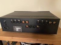
Its input can cope with different types of probes: direct, magnetic or electrostatic.

In the direct mode, it can be connected to a supply voltage, to detect residues of ripple for example.

The magnetic probe (typically a small drum-core choke) sniffs magnetic leaks from magnetic components or AC currents in a wire.

The electrostatic probe (typically a small pigtail left bare at the end of a coaxial cable) identifies unwanted capacitive couplings.

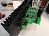
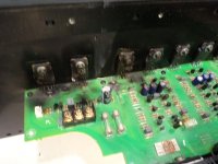
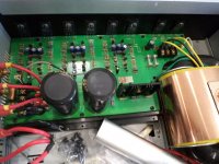
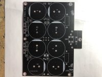
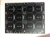
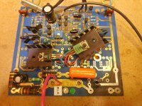
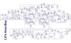
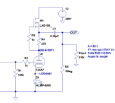
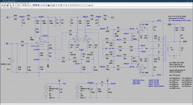
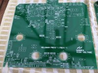
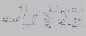
This is the circuit: it is just plain old analogue technology, nothing especially smart or fancy.

attachment.php


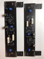
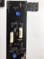
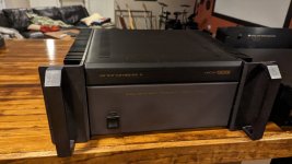
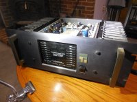
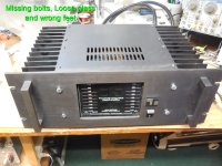
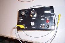
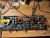
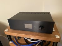
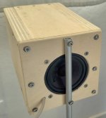
This is the finished tester:

attachment.php


I have included all possible bells and whistles.


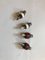
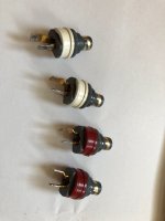
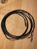
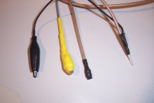
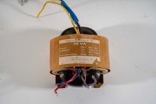
These are examples of probes:

attachment.php


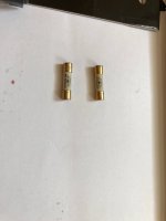
The yellow one is the general-purpose magnetic sensor: a 10mH choke, electrostatically shielded.

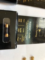
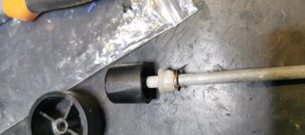
The black one is the miniature magnetic sensor, capable of locating a single wire in a bundle.
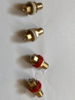
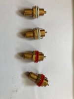
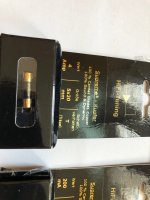
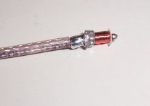
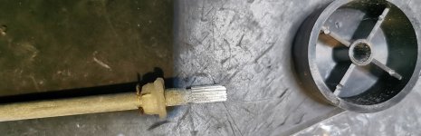
This pic shows its construction: it is made by winding a large number of turns of 0.03mm enameled wire around the center conductor of a miniature coaxial cable.

attachment.php


The inner conductor is made of steel, thus magnetic, and acts as the core of the inductor.
The inductance is 600µH and the resistance 50 ohm.

The last one is the E-type probe, also capable of accurately pinpointing a source.

The sensitivity is absolutely insane: in simple, audio-tracer mode, it is capable of eaves-dropping the audio from a regular telephone pair, without contact just by magnetic induction.
In bandpass mode, it is capable of detecting the 50Hz magnetic field generated by a 110kV HV power line from a distance of ~1 mile.

Attachments

  • HumBoy0.png
    HumBoy0.png
    67.9 KB · Views: 1,993
  • HumBoy1.jpg
    HumBoy1.jpg
    254.2 KB · Views: 1,912
  • HumBoy2.jpg
    HumBoy2.jpg
    173.5 KB · Views: 1,978
  • HumBoy3.jpg
    HumBoy3.jpg
    99.5 KB · Views: 1,938

Hypothetical DSP

So for starters: yes I know there are some great products out there like MiniDSP or HifiBerry and the like, but this is DIY and I want to make it to MY spec.

The idea was to use 4 ESS 9038PRO DACs (https://www.esstech.com/wp-content/uploads/2022/09/ES9038PRO-Datasheet-v3.7.pdf). Two for each channel (stereo) for full differential. ADCs as well, but I still haven't reached a verdict yet (Delta vs SAR). The main deciding factor there is if I want to meet the spec of the corresponding DACs, or if I just want to use audio ADCs simpley because that's what they were designed for. An additional two ADCs for return lines from the speakers themselves (signal attenuated to usable levels etc). Optimally, this would be all hooked up to a Sharc DSP. I like Sharc because I think Sigmastudio+ is a great solution for me because I am not the most amazing coder (admitedly I still need to learn more about CCES). That's the skinny of it. Analog Devcies has a good project board I was thinking of maybe using as a starting point (https://www.analog.com/en/design-ce...ards-kits/sharc-audio-module.html#eb-overview) but I am not sure if there is enough I/O for an expansion card to use the other ICs. I do intend to have the board made, although if I need to solder on some components, so be it. I do have hand solder experience.

At the heart of it, where would the design process for that start and is it possible to do as a DIYer?

Disclaimer: I am not an engineer. Just someone who really likes audio and knows a thing or two about electronics. I understand that, yes, this would be a massive undertaking. I am certainly open to criticisms because I do not know everything. But please do not post here if all you want to do is berate me and tell me I don't know what I'm doing. I am posting this because I know I cannot do this alone, and could really use some advice. I really like this forum. I've learned an immense amount in my short time here. But I also see the tendency for some to just brush something like this off, or use it as a stage for a soap box rant about what a moron I am. That's not why this is here. I am here to learn and grow and am willing to put in the effort.

So where to start?

Any real evidence that cartridge suspension degrades with time?

Looking at 10+ year MC (or MM) cartridge that has been seating on a shelf, do I have to care about the suspension loosing its compliance (or other mechanical properties)? The internet says that this is the case, but that’s found mostly on audiophile forums with not enough rational to back it up. I can see it is possible, but would like to see some data or even more scientific speculations backing this up.

Has anyone read about or measured this?

Oscilloscope Music?

Hey all,

OK, so Number One Son came home from college for Thanksgiving, and asked if I had an oscilloscope....I was initially surprised as to why he would enquire about one, aside from wanting to beat his younger brother over the head with it...

I showed him my two oscilloscopes (both have not been fired up in 10 years) and he asked a number of questions... I told him its for veiwing electronic wave forms...that was as simple as I could describe it - he is a Computer Science Major...

Anyway, he sent me to a YouTube vid on Oscilloscope Music...

Login to view embedded media
So question I had was is it possible to "harm" your system with uploaded internet waveform audio?

Beard P35

Hi, I have an amplifier designed by a French manufacturer around the 2000s, this amplifier looks a lot like the

Beard p35mkII,
the output transformers, the same models that integrate the JADIS amplifiers, because the manufacturer was in Toulouse.

I would like to improve this amplifier, if you can help me?

I started by replacing the capacitors that were out, but I think we can do better?
Regards
Gil

Attachments

  • 20230515_131258.jpg
    20230515_131258.jpg
    421.7 KB · Views: 227
  • 20231106_164951.jpg
    20231106_164951.jpg
    446.8 KB · Views: 227
  • 20231110_083243.jpg
    20231110_083243.jpg
    581.1 KB · Views: 311
  • 20231110_083255.jpg
    20231110_083255.jpg
    418.4 KB · Views: 218
  • 20231110_083302.jpg
    20231110_083302.jpg
    437.1 KB · Views: 212
  • 20231110_083308.jpg
    20231110_083308.jpg
    512.3 KB · Views: 204
  • 20231114_135230.jpg
    20231114_135230.jpg
    424.5 KB · Views: 188
  • 20231114_145611.jpg
    20231114_145611.jpg
    240.4 KB · Views: 179
  • 20231115_092146.jpg
    20231115_092146.jpg
    346.7 KB · Views: 208

Simple current source

Hi,
I'm reading the Bob Cordel Designing Audio Power Amplifiers (2011) interesting book and I have a doubt:
on page 37 (see attachment) it is said that the output impedance of the current source in the figure is 290Kohm. I get a different result. It should be Ro=ro(1+gm*Re) which is equal to approximately 1900Kohm, considering VA approximately 100V. Can anyone explain to me?

Attachments

  • Immagine.png
    Immagine.png
    26.1 KB · Views: 202

Transitional Two Pole Compensation.

Reminding the TMC.
Instead of feedbacking only the VAS by an integrating capacitor in Miller compensation, at low frequencies the output gets also included. This will decrease the distortion of the output.
With two pole compensation, only high frequencies are submitted into integration.
The problem occurs with TPC when the loop gain is too high, the upper audio band needs to be included in the integrator. The answer is LKA's 3 pole compensation or instead of integrating only the VAS, why not as with TMC include the upper audio band from the output to be integrated.
Bellow is a circuit designed by @lineup that I applied to.
https://www.diyaudio.com/community/...plifier-15-watt-with-tmc-and-laterals.406282/
ttpc.JPG

The global loop gain is promising 74db NFB @20khz. The inner loopgain showing 24db. By this the output stage is corrected by 98db@20khz.

Attachments

  • cello_amp TTPC.asc
    cello_amp TTPC.asc
    10.1 KB · Views: 82
  • outer loopgain.JPG
    outer loopgain.JPG
    163 KB · Views: 124
  • iner loopgain.JPG
    iner loopgain.JPG
    169.3 KB · Views: 118
  • Like
Reactions: minek123 and lineup

JL 1000/1 Gate Drive

Hello

I am working on a JL 1000/1 where I replaced all of the 2/3 way switches. It looked like the amp sat outside in the rain or something because all the switches had corrosion on them.

I tested the amp prior to replacing the switches and it powered up and played fine, although I didn't do a high power test.

Anyway, I replace all the switches and go to power it up to test. I usually monitor the amp with a thermal camera during power up and I notice one of the PS FETs getting hot. I power off and measure it, and it's shorted. I remove the bad FET and measure all the remaining PS FETs and they all measure OK. I try to power up again and now another PS FET is getting hot, ends up being shorted as well. I remove it and try again, it's like a chain reaction of failing PS FETs.

I decide to remove all the FETs and look at the gate drive. It looks unusual to what I'm used to seeing, square wave from 0V to 12V (or whatever my input voltage is). It is swinging from -13V to 14V. Is this normal? This is measuring directly across the FET from gate to source.

With all the original PS FETs removed, I put in two IRF7545, one on each bank of the PS and the amp powers up fine (idling around 2.4A). With the IRF7545s the gate drive still looks the same.

I'm not sure what happened to all the PS FETs when they were working before. The amp literally just sat in a box until the replacement switches came in. 😵

Attachments

  • IMG_1399.JPG
    IMG_1399.JPG
    444.1 KB · Views: 73
  • IMG_1400a.jpg
    IMG_1400a.jpg
    721.4 KB · Views: 76

Simple building block for high gain preamps - 12AX7 with single LND150 for CCS?

I've been mucking around with 12AX7s lately.
In the middle of building a phono stage, which is sidetracked with power supply issues at the moment. But, I was thinking of ways to more easily put together a couple of 12AX7 gain stages, and I came up with something really simple -- put an LND150 high voltage/low current MOSFET as a CCS in the 12AX7 plate. (Diagram attached.)

The advantage I see is that you can get a healthy 1mA of plate current through your 12AX7 with only a 250VDC B+, and still have a high enough voltage at the cathode to keep the 12AX7 out of grid current.

I whipped up the example with an LND150 as a simple, single-device CCS for the plate load, and a red LED for the cathode load. The B+ is 250VDC.

The results are encouraging.
Lots of gain - over 80X.
Low THD if the stage is loaded lightly.
THD is all 2HD.
No high wattage resistors needed, so it's cheap.

The LND150 dissipates 54mW in this configuration. I figure that's quite safe.

Does anyone use this? If so, does it work well, or are there hidden gotchas?
--

Attachments

  • 12AX7 with LND150 CCS plate load.png
    12AX7 with LND150 CCS plate load.png
    14 KB · Views: 2,551

USB-C headphone adaptor

Not DIY but hopefully someone can help. Wife has just upgraded her phone which now doesn't have a headphone socket but she does have a half decent pair of headphones she likes to use to listen to music on either plugged into laptop. USB-C headphone adaptors seem to start at $4 but at what point are they worth getting for a casual user who just wants it to last beyond the warranty period?

Observation TPA3118 + iPod G4

Only an observation when using an iPod G4 with a Wuzhi Audio ZK-601 mono amplifier using a TPA3118. Firstly the amp works fine with no bad behaviour on startup or shutdown and sounds OK. The odd thing is when the iPod is used as a source with it's volume at max all is well but when the volume on the iPod is adjusted below max there is high frequency noises and hiss. Return to max and all is well. I haven't come across this before with any other amp Class AB, D, T that I've used with the iPod. I've tried other sources such as a phone and a headphone output on another source which do not have this issue so it must be iPod related.

The amp's DC offset was 11mV when cold and close to 0mV when warmed up. The DC offset on the input using the iPod is 0mV at max volume but increases to 100mV+ when the iPod volume is decreased. This is measured at the input terminal block next to the used 3.5mm socket so may not be accurate. The only difference I can see compared to other modules I've used is that this appears to mix the stereo signal to mono.

It's not an issue as this is just a test amp for a mono test speaker that I use but is puzzling.

Attachments

  • TPA3118_ZK-601_a.jpg
    TPA3118_ZK-601_a.jpg
    66 KB · Views: 68

1 EF AMP

Most people use a leisure amp at low power averaging less than 5w but required to have 10 times headroom. This indicated a class AB amp. At low levels the crossover is the main trouble that results harsh high frequencies if the crossover is not right. Each pair follows a square law function, if a single EF is used as the case with CFP, the crossover can near perfection. With 2EF each pair should follow square law which results 4th order and 6th with 3EF which cannot get good crossover.
This Amp uses high current VAS that can pump 100ma in classA. To drive high gain high current a novelty is introduced in the IPS. The opamps are CFA amps with high bandwidth, by linking the negatives I transform it into symmetrical complementary differential, see the internal circuit, and by joining the outputs the supply current of each carries the error with over 100db gain. The output is biased 100ma and results 0.00014% 1w 20khz. It has 5v dropout which is too high.The AD8008 is ultra, ultra, ultra low noise, distortion, high frequency, that comes at cost.
It needs Zobel and Thiel ,the high impedance inputs can be Paduk way.


1EF 56w.JPG

Attachments

  • THD 20k 1w.JPG
    THD 20k 1w.JPG
    45.8 KB · Views: 339
  • ad8008.JPG
    ad8008.JPG
    25.9 KB · Views: 354

Sonix 600x/bryston 5b help

Greetings all, new but have learned a lot through reading. I have aquired a pair of sonics. Mine are the 600x or the 5b's guts. Next to nothing for info on the net, nada. I would like to use these in a monoblock set up, one per left and right fronts. The xlr LF output and the xlr crossover input have me pulling what little hair i have left out. Kinda new to this and totally new to xlr. These amps were gifted to me by a very close freind and would love to fire them up but am lost on how.
Any info from anbody woud be greatly appreciated.
Avr is a yamaha rx v 659
And the back of the amp

Attachments

  • 20231129_103602.jpg
    20231129_103602.jpg
    514.6 KB · Views: 92

Amplifier Help - Sonics 800x (Bryston 7b)

So I ended up with a pair of Sonics 800x amplifers (Bryston 7B NRB amps with a custom input stage) that are in perfect condition, and I enjoy the sound. Unfortunately, as they lived their life in an IMAX theater before I got them, they dont have soft start, or speaker protection circuits, or a power button. I am looking at adding those items, as well as re-capping it, since it is 30 years old this month.

I will admit total ignorance in the electronics area, but I was looking at the boards diyaudio offers (Soft Start & Speaker Turn-On Delay / DC Protector Combo – diyAudio Store). Am I incorrect in assuming these should work for my needs?

Does anyone know of someone who would be willing to take this on (or really mentor someone through this process)? I am in the central ohio area if it is of any difference.

Bass Speaker Box

Hi I have a couple of Celestion Pulse 10 bass speakers and looking to build a box for them. The specs on the speakers are Fs 66.3Hz, Qts 0.444 and Vas 1.06 cubic feet (thats for one).
Can anyone tell me if these speakers would be suited to a sealed or ported box. Have a idea of a ported box with a volume of 2.7 cubic feet and Fb of 40Hz and have managed to draw some responce grapths but any opinions would be gratefully received.

Precision Power PC650

I have a PC650 that has developed slight turn on thump and a more significant turn off thump on all channels that I need some help solving.

The current configuration on the test bench has one pair of speakers attached to the rear set of outputs and a single woofer attached to the subwoofer outputs in bridged mode. I have the input board removed, but it makes no difference in or out and gain controls do not make any differences.

The turn on thump is about equal timing on the three speakers. The turn off thump happens twice and isn't always equal on all three speakers. DC offset measurements on each channel can be observed at startup and shutdown. While the amp is operating the DC offset on each channel is at acceptable levels.

This amp does not use the ceramic driver boards and it also uses 7915/7815 as regulators. It does have the 4n25 optocoupler in it, but I don't measure anything wrong there.

Any tips are appreciated.

NAD 3140 Conversion to lateral FETS

So after the real success of doing the 3020 and 3130 ive decided to do the 3140
You dont see these about much these days-i dont thnk as many were made like the other 2

Few different challenges on this one, particularly the sighting of the FETS-Ii might need a different heatsink, we will have to see

So part one is the dismantle and check it over- and this is what i do to all of my amps as a standard proceedure
someone kindly glued the knobs on-a little bit of gentle heat and they are all off
the spindles will get cleaned and buffed up before they go back on
all screws will be removed and resprayed
cover and base plate are cleaned with Mr muscle(i find this the best and least agressive) then they will be stored away

looks like someone kindly recapped this before i brought it, that was good of them wasnt it

Whats left is cleaned in 3 stages
first it is hoovered out, then blasted with compressed air to get rid of any dust
then i clean with 2 different cleaners-holts electrical contact cleaner, then AAB contact cleaner, this leaves a nice finish

Next step once all is dry will be to check the amp over to make sure there are no nasty suprises or faults before i start the conversion

Attachments

  • IMG_20230317_071658.jpg
    IMG_20230317_071658.jpg
    117.5 KB · Views: 257
  • IMG_20230317_071709.jpg
    IMG_20230317_071709.jpg
    158.4 KB · Views: 259
  • IMG_20230317_071754.jpg
    IMG_20230317_071754.jpg
    159.9 KB · Views: 251
  • IMG_20230317_072522.jpg
    IMG_20230317_072522.jpg
    420.5 KB · Views: 291
  • IMG_20230317_072924.jpg
    IMG_20230317_072924.jpg
    404.6 KB · Views: 288
  • IMG_20230317_073456.jpg
    IMG_20230317_073456.jpg
    227.1 KB · Views: 266
  • IMG_20230317_073512.jpg
    IMG_20230317_073512.jpg
    296.9 KB · Views: 253
  • IMG_20230317_074751.jpg
    IMG_20230317_074751.jpg
    579.7 KB · Views: 268
  • IMG_20230317_080035.jpg
    IMG_20230317_080035.jpg
    309.2 KB · Views: 300
  • IMG_20230317_080039.jpg
    IMG_20230317_080039.jpg
    191.3 KB · Views: 223
  • IMG_20230317_080103.jpg
    IMG_20230317_080103.jpg
    222.8 KB · Views: 218
  • IMG_20230317_080108.jpg
    IMG_20230317_080108.jpg
    348.2 KB · Views: 219
  • IMG_20230317_080116.jpg
    IMG_20230317_080116.jpg
    124 KB · Views: 238
  • IMG_20230317_080627.jpg
    IMG_20230317_080627.jpg
    146.9 KB · Views: 259
  • Like
Reactions: Freedom666

KT88 PP - Dotting the Is, crossing the Ts

Alright, the subject is pretty self explanatory, I'm at that stage of a design where I'm dotting the i's and crossing the t's. Below is the schematic which represents the status quo of the current prototype with an actual measurement of THD v.s. output power at 1kHz included. I've obviously tried just about every trick in the book, hence the fact this is the 30th revision of the prototype schematics, some revisions were small just a resistor value change, some larger, and I am hoping to get some suggestions on how to improve THD > 20W, as currently the THD rises significantly after that point. I have the prototype on the bench, and the simulation running on the PC and interested to try suggestions, as I'm sure there's still room for improvement! Looking forward to your replies!

Attachments

  • proto30_schematic.jpg
    proto30_schematic.jpg
    494.5 KB · Views: 610
  • proto30_thd_vs_pow_1khz.jpg
    proto30_thd_vs_pow_1khz.jpg
    193.4 KB · Views: 602

How to mod old Class AB AMP to make it over current proof

Hello,

I had repaired an old Trace Elliot GP7 SM300 (300W bass amp from a friend). Some transistors defective and a break on a pcb trace, which will have been the cause of it's first death. During the test on a 15" (4 Ohm) i cranked up the volume and at a loud level all the transistors went into meltdown again. After some research, the design basically does not seem to be so super destruction-proof. I assume the repair attempt was actually successful, it was just too much somewhere during testing.

The question: can the circuit be made a little more damage-proof with a manageable amount of effort?
gp7sm300.jpg


There was already a modification (by someone else). The red resistor was soldered on the bottom side of the PCB.

The service manual is available here, for example: https://elektrotanya.com/trace-elliot_gp7_150-300watt_sm.pdf/download.html if necessary.
The toroidal transformer is primarily fused with T3.15A and there is approx. +-70V after the rectifier.

In my test at the moment when I was turning louder, the following transistors broke: TR 11 and on the +V side: 13,14,16 and on the -V side:
5,6,7,15 and the transformer fuse.

I had previously checked the DC offset, and a 1kHz sine wave looked clean on scope (does this bring more stability to reduce the quiescent current,
and e.g. rather have 0.5% THD instead of 0.01%?)

For Sale ZenMod Iron Pumpkin AVC preamplifier

Built with pride in Slovakia 🙂 by ZenMod.

Top of the line model with Finmet AVC, Toshiba JFETS. 2x RCA inputs, 3x Balanced inputs and a pair of both SE and balanced outputs.

24 step volume control. Remote control works spot on.

It has 0dB to +8dB gain which can be selected by internal jumpers.

Seriously great preamp, I’ve tested it against Don Sachs 6SN7 preamp (with the nice LINLAI Global Elite 6SN7) and also against Holo Audio Serene. It performs in the same league, and it’s the one I kept - but I now find myself going DAC direct. Iron Turtle neither adds or takes away, it’s just that I don’t need it anymore. It only has about 300hrs on it and is as new. I am the original owner.

Asking £1,600 + shipping or collection from Oxford, UK

Attachments

  • IMG_4219.jpeg
    IMG_4219.jpeg
    357.8 KB · Views: 426
  • IMG_4221.jpeg
    IMG_4221.jpeg
    373.7 KB · Views: 351
  • IMG_4220.jpeg
    IMG_4220.jpeg
    297.8 KB · Views: 407
  • IMG_4217.jpeg
    IMG_4217.jpeg
    341.8 KB · Views: 417

Vituixcad FIR crossover

I have designed a digital crossover and exported the impulse response. When looking at the hipass filter frequency response with REW it appears that the low frequency attenuation is quite poor, REW shows a positive slope. At 2Hz attenuation is only 20 to 30dB and continue to rise I guess up to 0dB at 0Hz.
Here is a plot of a simple LR36 at 8KHz:

fr-hipass.png


I should have missed something but can't figure out what...

joël

Source of cheap power transformers

Hi,
I'd like to share a recent experience. I've been looking at low cost power supply solutions for pre- and headphone amps, and after a bathroom refurbishment at home I noticed a very nice isolation transformer in the shaver socket. I quickly bought two second hand on ebay for £5, and was pleasantly surprised to find a 20VA transformer with a tapped secondary. Tried both full wave and bridge, with load currents in excess of 50mA DC. Full secondary DCR is 140 ohms. Add a small smps for heaters and there is a low cost solution. Not for everyone, but may be of interest for some.

1000010392.jpg

1000010391.jpg

Are Tesla speaker TS values useful?

Upgrading the drivers on my Model 3 left me with the OEM tweeters/mids/woofers (and an OEM sub that I thought I'd install but decided not to risk the warranty).

Since then, I've gotten into making bluetooth speakers for family/friends and have learned how to use DATS/Winisd/REW/VituixCAD2 to get better results.

I'd been unable to find the TS values for the Tesla speakers online, so I recently measured them myself using DATS v3 and added mass. I realize this is a niche use case, but does anyone have a recommendation on where I can post this info online to help the next person that might want to reuse these drivers? Perhaps the values could also help car audio people better understand Tesla's design decisions to aid in their projects.

Thanks for any ideas! Here's an example of what I captured for the mids:

1701800081241.png

CL0800 – Satellite with 3FE25 in closed box, original stand and wiring

This CL0800 project is a closed box satellite with directional frontal emission.

The driver is a Faital-Pro 3FE25 already used in previous MDD projects. The CL0800 satellite sounds good although limited in bass.

The case is oversized, I will need it as a compression chamber in the next MDD project.

Construction is simple and inexpensive. The unconventional stand has a subsonic resonant frequency at approximately 1 Hz, isolating the satellite from the floor in audio band. The wiring is original in that the negative pole wire passes behind the radius of the basket in ferromagnetic material, avoiding inserting material inside a coil that can generate hysteresis phenomena and consequent distortion.

I have placed various links to old documentation on MDD projects on the "before" and "after" pages.

Thanks for the attention

https://www.claudiogandolfi.it/cl0800.html
https://www.claudiogandolfi.it/prima.html
https://www.claudiogandolfi.it/dopo.html

Attachments

  • 00stepright.jpg
    00stepright.jpg
    53.4 KB · Views: 93
  • 00THDright.jpg
    00THDright.jpg
    98.1 KB · Views: 101
  • 00r04.jpg
    00r04.jpg
    133.9 KB · Views: 105
  • Like
Reactions: mayhem13 and GM

Quasion on relay volume control

Hello all

I am on the way of designing and coding the relay volume control. I will use this resistor arrangement with 7 or 8 relays allow me to get 128 or 256 steps of attenuation. I use online calculator to get the resistor value to get more the 100 db attenuation.

My question is, with this resistor and relay arrangement, I notice that even at the lowest step/position which should be no signal out but at the lowest step it does not bring the output to ground like normal attenuator. Does it be completely silent at the first volume step? or I do need one relay to short the output to ground to make it silent?

Thank you for every help
Tanwa


arivel-relay-42.gif

Modern KEF B139 Triangular Transmission Line

@PK1, your emails are bouncing.

Peter contacted me about this design that i did in 2006 (Scott’s alignment).

B139-TTL-3D-dispay.png


The original sletch from the late ’70s was for the B139, modern modeling showed it was almost right on for the Jordan JX150, and when Scott came up with the alignment i drew up some potential ideas. I don’t know if the TTL has been built, but i have been contacted a few times before. Other versions of the same alignment have been built and were reported to perform well.

I’d really like to see one of these done.

I have updated that drawing (cosmetics and comments only), and i did do a sketch for driver placement for another chap. I have enclosed the updated drawing.

I have given bracing much thot, still not quite sure how to best execute. Bracing the driver and baffle against at least the inner partition i would consider minimal. The angled partition braces all the other panels but the top.

https://www.t-linespeakers.org/download/TriangulatedTL-B139-050923.pdf

dave

Simple Sub amp

Hi, I'm currently building a simple amp for a 10 inch 150w subwoofer for a friend.
I don't have LTSpice models for mj11015/mj11016 , I just simulated with BD and some 2SC/2SA might not be the way to go, but...

  • Using darlingtons in the output stage might be harder to keep them not thermal run away? Should I place Q5 on the heatsink with the output trans or close to it?.
  • is it ok to limit the bandwidth with C12 ? or I should not and build a op amp based low pass filter at the beginning.?
* use low pass filter and also limit the bbandwidth as well? since it won't play past 150hz.

- 100W output is what I aim here. 200W 30A output transistors I think are sufficent , Since you can get 60W from a pair of 2SC4468/2SA1695 100W/10A trans.

- Bruno.

Attachments

  • swampv1.JPG
    swampv1.JPG
    127.1 KB · Views: 441

Differential 9 Power Amplifier

Hey all, haven't been here for a while, nice to be back. I'm planning to build a pair of Marantz Model 9 amps this winter and I have a question. I'm awaiting the arrival of a pair of Sowter input transformers, 10k/10k. I bought them because the English economy is on the skids and the price was very good. I would start by fixing the low frequency filter. And also do away with the phase inverter and the first half of the 6DJ8. But my real question is about conversion to a differential amplifier with a transformer input. Would it compromise the quality of the amp? Or is it build it and see thing?

For Sale WBT-0210 Cu nextgen RCA socket - 4 piece & ETI Research PhonoPod, TeCu Gold Plated Female RCA socket - 4 piece && HIFI TUNING SUPREME 3 COPPER Fuses

WBT-0210 Cu nextgen RCA socket - 4 piece


light used in excellent condition.

WBT-0210 Cu/CuMS nextgen RCA socket | HIFICollective

WBT-0210 Cu/CuMS nextgen RCA socket

Purchased from Hificollective for £108.

Selling at £60
including PayPal charges 5.5%.

ETI Research PhonoPod, TeCu Gold Plated Female RCA socket - 4 piece​

light used in good condition

ETI Research PhonoPod, TeCu Gold Plated Female RCA socket - DISCONTINUED | HIFICollective

ETI Research PhonoPod, TeCu Gold Plated Female RCA socket - DISCONTINUED

Purchased from VH Audio for $116.

Selling at $60 including PayPal charges 5.5%.

HIFI TUNING SUPREME 3 COPPER SLOW 5 X 20MM (T) AUDIO GRADE FUSES​

Audiophile-Grade Fuses, Your system will play with increased power, dynamics, clarity, and coherence.

Available for sale is 200mA and 4A.
light used and in excellent condition.

Purchased from Analog seduction UK for £45 each.

Hifi Tuning Supreme 3 Copper Slow 5 x 20mm (T) Audio Grade Fuses

Hifi Tuning Supreme 3 COPPER Audio Grade Fuses
www.analogueseduction.net

Selling at each £30 including PayPal charges 5.5%.

HI-FI TUNING GOLD PLATED SILVER CERAMIC SLOW 5 X 20MM (T) FUSES​

Audiophile Fuses: Hand made in Germany, pure silver wiring, gold over silver end caps, ceramic casing, cryogenically treated.

Available for sale is 7A and 8A.
light used and in good condition.

Purchased from Analog seduction UK for £35 each.

https://www.analogueseduction.net/fuses/hi-fi-tuning-gold-plated-silver-ceramic-fuse-10-amp.html


Selling at each £20 including PayPal charges 5.5%.


Shipping to Worldwide at buyer's risk, but it will packed carefully.

Shipping to world will be through INDIA post Registered mail which will take 2-4 weeks.

Please contact me for shipping charges.

Thanks for looking.

Attachments

  • IMG_4035.JPG
    IMG_4035.JPG
    322.1 KB · Views: 128
  • IMG_4036.JPG
    IMG_4036.JPG
    313.3 KB · Views: 120
  • IMG_4037.JPG
    IMG_4037.JPG
    326.8 KB · Views: 125
  • IMG_4038.JPG
    IMG_4038.JPG
    350.3 KB · Views: 113
  • IMG_4039.JPG
    IMG_4039.JPG
    332.6 KB · Views: 102
  • IMG_4040.JPG
    IMG_4040.JPG
    320.8 KB · Views: 116
  • IMG_4041.JPG
    IMG_4041.JPG
    328.6 KB · Views: 111
  • IMG_4042.JPG
    IMG_4042.JPG
    480.4 KB · Views: 101
  • IMG_4043.JPG
    IMG_4043.JPG
    478.4 KB · Views: 135

Phono preamplifier with DC servo: precorrecting RIAA correction poles

Hi all,

I sometimes see people trying to put DC feedback loops around phono preamplifiers. When you put a DC servo loop around a phono preamplifier, the feedback shifts the poles, particularly the lowest one, and may mess up the RIAA correction accuracy. One way around that is to deliberately shift the correction network poles such that they end up where they should be with the DC servo loop closed. I did some calculations about that, see the attachment. I hope it will be of use to someone.

Best regards,
Marcel

Attachments

Is PRV's 10FR300 getting any love?

at $69US and 10 inch it has no competition - a tapered line - ABC - partially filled reflex should work well. My 10FR300 is stuffed into a tiny 0.62 scale K15 Karlson and has one fake Scotch Brite pad over its vent - not sure how much good that does with its 28 liter rear chamber.

I'd imagine something useful could be done with 60 liter;s airspace.

Attachments

  • 0.62 SCALE K15 WITH PRV 10FR300 FULLRANGE AND FAKE SCOTCH-BRITE VENT INPUT IMPEDANCE 1.png
    0.62 SCALE K15 WITH PRV 10FR300 FULLRANGE AND FAKE SCOTCH-BRITE VENT INPUT IMPEDANCE 1.png
    163.5 KB · Views: 127
  • Like
Reactions: GM

Triangular BIB?

Ever since I came across this (I was perhaps 12) I've always wanted to build one - a friend of the family had one with a marble baffle. One day I will - and I have the perfect old barn to convert to house them.

But... it set me thinking. Would it be possible/desirable to build a similar thing for a BIB? Using two solid walls (and I do mean solid with no cavities behind plasterboard) and a front baffle of good play would it work for a BIB? If one got the cross-sectional area and height correct as per the BIB calculator? Such a thing would blend well into a wall and be hardly noticeable.

(Furthermore the WAF measurement could be enhanced by wallpapering the entire room and the front baffle with woodchip painted with magnolia emulsion.)

Last comment aside it IS a serious question!

a3NpM1a.png

My VOT replaced by a "Super VOT", the Yamaha S6215

Dear all,

After many years of satisfaction and enjoyment, I found an opportunity to upgrade my system.

I started with the replacement of my 1505B driver, a 291-16A, with a Yamaha 6681B. Amazed by the result, I started to study a bit more about Yamaha loudspeakers and I found that the 15 inch 3882 could be an excellent bass loudspeaker for a front loaded horn like the VOT.

Finally, I discovered this bass cabinet, the S6215, with two 3882 and more a less the size of my A5. They were in LA and I found a way to get them shipped to Europe. So all loudspeakers are Yamaha, including the excellent tweeter 4281B. Only the 1505B is still Altec.

The result is just outstanding... I am using a passive crossover and Jriver for small EQ adjustments.

Attachments

  • _DSC2036.jpg
    _DSC2036.jpg
    351 KB · Views: 859
  • Thank You
Reactions: GM

An RH84 is half born

I started ordering parts 10 1/2 years and 2 houses ago. Now it's mostly mounted on a chunk of 3/16ths aluminum.

Jan 12AT7
Russian 7198 equivalents
Coke bottle 5U4
Hammond 272.....EX?
Hammond 20H choke
Trancendar OPTs. 5k:8Ohm

Next step is a plywood cradle for it to sit on during the build.

I'm going to do some sort of fancy wood frame upon completion.

I'm mounting the power cord and fuse on the base. I'll move the switch there if it seems to be a noise issue.

Ignore the plugs next to the power tubes. I realized I was probably going to burn myself using the volume knob and power switch. Makes for a sub-optimal listening experience. Live and learn. This is my first tube/valve chassis.

Hopefully people posting will guilt me into continuing progress!

Stay safe.

PXL_20231020_044424955.jpg

China IRS2092 Modifications?

I could not find a quick-n-dirty place where this info was already compiled, so figured I would start a new thread here.

Quick back-story: I am "rebuilding" a couple dayton plate amps that have been repaired so many times that I am just tired of messing with the original design. So I have traced down the pinout of the original pre-amp section (with xover, phase, level, auto-sense, etc) and will interface that with a cheap IRS2092 module I got from China.

Here is a pic of the board I got:
IRS2092.jpeg


Now for the (possible) issue...

I have read that there are a couple resistors that this board commonly ships with that need to be replaced?

Seems I recall EVMan asking me about this (but I cannot find the post where he asked me to save my life) and...

Furthermore, he made mention that R11 an R13 on his samples arrived with the "wrong" values.

The 2 samples I have arrived as follows:

R11 = 10K
R13 = 100

I am NOT SURE if the resistor number (R11 and R13) correspond 1:1 with the resistor numbers on the IR reference design sheet that I found online - which further has me a bit afraid to just start swapping out resistors.

From what I have gathered, R13 should be replaced with a 3K (currently 100R) to reduce the gain a bit (better SNR?). Seems this would be a very important "update" or "fix".

Additionally, some have mentioned replacing R11 with a 8.2K (currently 10k) - has something to do with the switching frequency I think? How important is this "update"?

If someone has any experience with the particular version I have shown above, any feedback would help a lot.

Some additional notes:

I would assume it is safe to replace the gain resistor (R13, 100R) with a normal through-hole resistor carefully soldered to the pads - cannot imagine much issue here.

The OTHER resistor - R11... That one is literally right next to the chip and in a spot that I may not easily be able to do this without having leads of a couple inches to/from a normal through-hole resistor. IF I have to replace THIS resistor - would the length of the leads cause any issue with inductance, etc? In other words - will this particular resistor NEED (more/less) to be replaced with another SMD?


I plan to use this board with a +/- 62VDC power supply pushing a 4 ohm load. Anything over 200 watts is more than I need for the given application.

Tubelab Universal Driver Board, 2015 version

The Universal Driver Board (UDB) was a concept that was underway in 2009 when the 6L6GC in AB2 thread appeared. The design concepts are discussed throughout that long thread. The circuit features two cascaded LTP's made from dual triode tubes. I have made several different versions of a similar design with 9 pin miniature, and octal tubes. The Octal version was used for Chrish's amp design, and for my test breadboard. Several different types of output tubes have been tested through my breadboard. The thread is here:

http://www.diyaudio.com/forums/tubes-valves/133034-6l6gc-ab2-amp.html?highlight=6L6GC+AB2

Shortly after Chrish's amp was done, it became evident that my engineering career was in jeopardy, and I had to devote most of my time to keeping it alive, so my amp never got finished. In 2014 my 41 year engineering career ended, so we packed up everything and left south Florida. The "6L6GC" thread fell into a 4 year sleep during that time.

It turned out to be a hasty exit and I had to sell, give away, or trash over half of my stuff. What was to be a long careful packing, labeling and moving job got compressed into 3 weeks, so things were essentially randomly packed. The breadboard built during that amp design effort has never been found, so I assumed that it was lost, and set out to build a new one.

I laid out a new board that used 9 pin tubes since there are far more different flavors to choose from. I had a batch of the boards made by a commercial PCB vendor, since they were to be the next Tubelab product. That was early in 2015. About this time my daughter returned home with 4 kids and a husband, which we are supporting, so Tubelab again got pushed back into the corner. That situation has still not been resolved, and often requires most of our time. In the exit from Motorola and south Florida, I also lost access to my web site. I am working on that as well, but that's also why there hasn't been any recent updates.

The batch of UDB's sat in their shrink wrap on the shelf, until we moved again into a bigger house. In late 2015 Chrish woke up the original thread, which prompted me to build a pair of my UDB's and a new breadboard. First seen in Post #630, the board, and new breadboard finally saw life in early 2016, post #651. There have been a few random tests since then, but nothing too serious, just 250 watts from some transmitting tubes.

I have ideas on building a few amps using these boards, and I have sold 4 of them, so it's time to put together some documentation. There will be more posts in this thread in the coming days with real data on test amps. The initial choices for output tubes is KT88's, and the amp has already been fired up on bench supplies.

Service CAV A8M

Doesnt happen very often so those who did it deserve the credit .

The CAV A8M comes into the shop badly burned since the costumer plays in the rough side i think probably too loud with heavy loads while the amplifier has been repaired ( badly also ) previously

Inside the notorious SAP 15-P-N inside a circuit that proper balance is very important to achieve stability .Seems that the amplifier has been repaired in the past more than once , probably by the local distributor , and wears inside all shorts of available versions of SAP 15 ...Obviously this is not the way to achieve stability .


On factory though the quality of make , order , symmetry and arrangement on the boards is exceptional for this type of product .After a quick argument with the local distributor who claimed that he never had a schematic a quick phone to Jenny and Ken proved to be a walk in the park and before i hung up the schematic was in my inbox .

That is a service minded company and in the feature i will never question getting a CAV product Already have a pair of speakers that i am thrilled with .

Well done Ken , Jenny thanks to your service minded policy the A8M is up and running again !

In between enjoy some pictures of the repair ...
Kind regards
Sakis

Attachments

  • DSC02629.JPG
    DSC02629.JPG
    98.1 KB · Views: 589
  • DSC02630.JPG
    DSC02630.JPG
    98.4 KB · Views: 481
  • DSC02631.JPG
    DSC02631.JPG
    101.9 KB · Views: 464
  • DSC02647.JPG
    DSC02647.JPG
    494.6 KB · Views: 549
  • DSC02648.JPG
    DSC02648.JPG
    129.6 KB · Views: 832
  • DSC02649.JPG
    DSC02649.JPG
    119.4 KB · Views: 883
  • DSC02650.JPG
    DSC02650.JPG
    123.6 KB · Views: 414
  • DSC02651.JPG
    DSC02651.JPG
    127.5 KB · Views: 406
  • DSC02652.JPG
    DSC02652.JPG
    383.1 KB · Views: 432

Choosing the mains transformer for preamp

Hi guys,

I am building a tube preamp using either 6n2p-ev or ECC85 (not decided yet) in SRPP, so B+ current is very small, let's say, 75-100mA should be enough for two tubes, and heater currents are either ~340mA (6n2p-ev) or 435mA (ECC85), so let's round up to 1A for both. Plus, I'd like to use a tube rectifier EZ81 (in half-wave mode), it adds 1A more to the heater windings.

Here is the list of the transformers I am choosing from (a compromise between the quality, price and availability in EU) https://sklep.toroidy.pl/public/assets/Mains_for_tubes_ENG.pdf

The model 80/001 with 275V (0,12A) and 3,15 - 0 - 3,15V (7A) or even 80/002 with two heater windings fits perfect, but my concern is a size of a transformer, as it should fit into a limited space of the integrated amp (I'm replacing its low-quality build-in preamp) i.e. it's diameter might be <= 90mm. If going down to their 60/002 model (which is 86mm in diameter), it'll give only 3,15 - 0 - 3,15V (2,5A) (let's ignore its lower B+ atm).

So, my question is if currents in this list are already given provided a 50% power overhead or not? Does anybody have an experience with regards? I mean, according to all recommendation across the internet I need something capable to give at least 2A x 2 for heaters, but maybe these transformers are already good enough providing the real specs?

Or one can say no, only 80VA models, then I'll try to fit it, maybe, cutting off for these 5mm here or there =)

Flamma FS06 Preamp Troubleshooting

Hi Folks! I am having a bit of trouble with Flamma FS06: the level knob does nothing, and the saved presets kinda "unset" themselves. Let me elaborate.

This pedal has five standard knobs: three-way equalizer, level and gain. And it can "remember" the specific setting, for each of the 14 emulated modes, when one presses and holds the "select" button.

I recently noticed that my level knob does nothing: I turn it all the way back and forth, and there is no change in the output whatsoever, in any mode.

Gain and frequency knobs work fine.

I also noticed that the saved presets sort of unset themselves in a couple of seconds now: when I save the preset, the light indicator for the selected amp model blinks a few times and then it is supposed to stay on unless I touch the controls and change the settings. If I do change the settings, the light starts blinking indicating that the setting is now different from the saved preset.

Well, now the indicator starts blinking again in a couple of seconds after I save a preset even if I touch nothing and change nothing.

I kinda think that these two mulfunctions are related: the level knob reports something to the device which makes it think that I am changing the preset.

I tried to find some kind of customer support on the Flamma web site but found only chat, which noone responded to so far. I tried Amazon, where I bought it, but it's been over 120 days, and they won't do anything.

Any suggestions? Anyone thinks it's reparable?

Here it is:
1699648184945.png

1699648199554.png

Will A Modern Inexpensive Outboard DAC (e.g. Schiit Modi3+) Improve My Old CD Player’s Sound Quality?

Firstly ...I didnt know which forum to post this question in, but its kinda (very) analog in nature🙂
And so moderators, please move as you see fit.

HI Folks
I am putting together a secondary system based primarily on vinyl but also including CD format.
This system will get used a lot as its in the den just off the kitchen so of course I am looking for decent sound.

Regarding the CD equipment… I have two typical mid 90’s CD players that have both digital RCA out and Toslink output ports.
I would like to put one of them back in to service in this secondary system.
They have both proven to be very reliable over the years and so I would like to stick with them.

But my understanding is that DAC’s and the analog sections that follow the DAC have come a long way since these old CD players were sold.
So I am thinking of using these CD players as transports and buying one of these new thoroughly modern but inexpensive DAC’s.

But will doing this actually improve the sound over what these (old tech?) garden variety players can provide?
And are these new DACs a good fit for this purpose or are they really intended for something else?

Thank you all and best regards.
Curt

  • Poll Poll
"Serious Pre" Tube Build

Who would like to follow and maybe help?

  • Hell Yeah

    Votes: 7 87.5%
  • Nah...

    Votes: 1 12.5%

I am building a tube preamp to go with my custom built Turntable and DAC .... I know nothing about tube amps - everything I know I learned from another forum user on DIY who told me I should build a "serious preamp" and helped me source parts. I'll let him identify if he wants to, but he was ok for me to share.

Will need more help and advice along the way as this is a tough project I think for me. I'm calling it "Serious Pre" in honour of the inspiration.

Overview
  • Single input (SE or balanced), Single balanced output (could be SE if desired but who would want that!)
  • Two volumes - one for each channel therefore balance not required.
  • Simple design derived from Japanese magazine April 1993, one signal tube (5687) split for both channels, 3 resistors and one cap for each channel
  • Power transformer re-purposed from vintage Kenwood W-24 amplifier, One rectifier (6x5 tube) Two new mouser transformers for heaters
  • Tango output transformers (anyone know how to source them from Japan online?)
  • Vintage caps, resistors, voltage and amp meters, tubes
  • Tocos Cosmos pots
  • zero extraneous components that aren't needed to improve the SQ (but the meters are cool and vintage)

Fusion360 Mockup (not actual parts but rather conceptual right now)
SeriousPre_2023-Oct-17_02-12-06AM-000_CustomizedView2826589005.png


Based on this April 1993 circuit with substantial? modifications provided to me by the DIY inspiration user ....no Phono stage, single 5687 for both channels, etc.
IMG_8449.jpeg

Attachments

  • SeriousPre_2023-Oct-17_02-25-49AM-000_CustomizedView636923584.png
    SeriousPre_2023-Oct-17_02-25-49AM-000_CustomizedView636923584.png
    258.8 KB · Views: 292
Projects by fanatics, for fanatics
Get answers and advice for everyone wanting to learn the art of audio.
Join the Community
507,774
Members
7,887,955
Messages

Filter

Forum Statistics

Threads
406,208
Messages
7,887,955
Members
507,774
Latest member
pete2000